The 12-volt 1.3AH battery charger circuit diagram is a highly practical design that utilizes the L200 voltage regulator and an over-voltage protection circuit. It employs an optocoupler to provide feedback, allowing precise control of the voltage across the battery by efficiently toggling the L200 voltage regulator on and off. This circuit diagram is an excellent solution for charging a 12-volt 1.3 Ampere-hour.
Battery chargers have enormous applications, from domestic use to industrial use. A battery charger, as its name suggests charges batteries. Battery chargers are used in UPS battery chargers, car battery chargers, solar battery chargers, and many other applications. In this article, I am discussing a 12-volt 1.3AH battery charger.
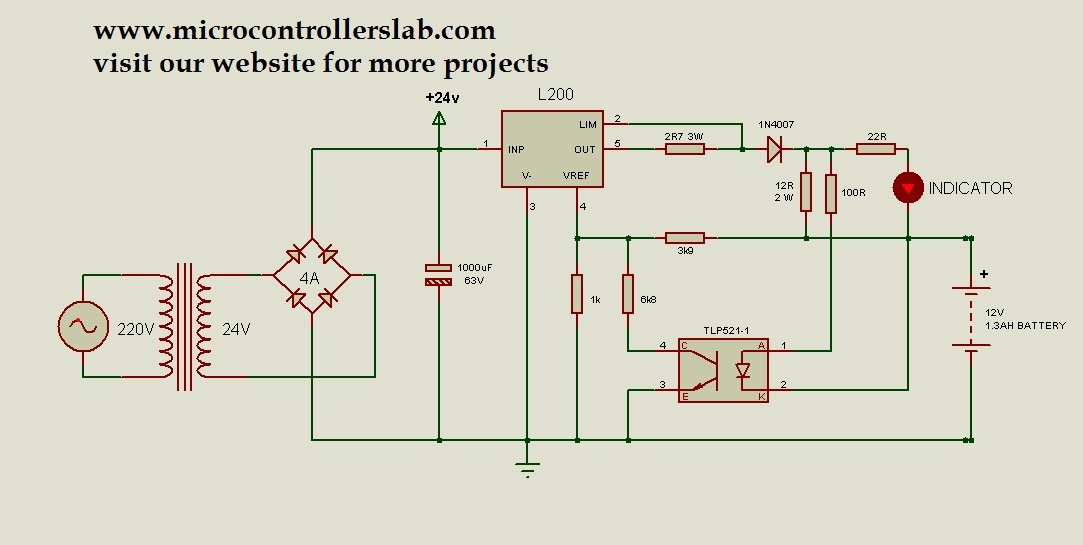
12 Volt Battery Charger Circuit Diagram
The circuit diagram of a battery charger is given below. In this circuit diagram, an LED is used as a voltage indicator to show charging. When the battery is charging, the LED will glow. Otherwise, it will remain off.

Components
The circuit diagram provided shows the schematic representation of a 12-volt 1.3AH battery charger circuit. Let’s break down the components used in this circuit:
- A step-down transformer is used to convert the high voltage of 220 volts AC into a lower voltage of 24 volts AC.
- This circuit uses a 4A rectifier to convert the AC voltage from the transformer into pulsating DC voltage.
- The rectifier converts the AC voltage from the transformer into pulsating DC voltage and is followed by a 1000uF capacitor to smoothen the output voltage.
- The L200 voltage regulator controls and regulates the output voltage, providing a constant output current of up to 2A and varying the output voltage based on the reference voltage.
- The TLP251-1 optocoupler senses the voltage across the battery and adjusts the reference voltage of the L200 voltage regulator accordingly.
- The 1N4007 diode limits the output current to 700mA, protecting the battery from excessive current flow during charging.
- An LED is connected as a voltage indicator in this circuit. The LED glows when the battery is being charged, indicating the charging process. If the LED remains off, it means that the battery is not being charged.
These are the main components of the 12-volt 1.3AH battery charger circuit. Each component plays a specific role in regulating and controlling the charging process to ensure safe and efficient charging of the battery.
Working
The above circuit diagram uses a 220-volt to 24-volt step-down transformer to reduce the voltage to 24 volts AC. Then, it utilizes a 4A rectifier or a 4A diode connected in a full bridge configuration to convert the AC voltage to pulsating DC. Additionally, it employs a 1000uF capacitor to smooth out the ripples in the pulsating DC. Finally, it supplies the constant DC voltage to the input of the L200 voltage regulator.
Applications
Battery chargers have various applications in different fields. Here are five common applications:
- Portable Electronics: People commonly use battery chargers to charge the batteries of portable electronic devices such as smartphones, tablets, laptops, and smartwatches. They provide a convenient way to keep our devices powered up while on the go.
- Automotive Industry: The automotive industry relies on battery chargers to maintain and charge the batteries used in vehicles.
- Renewable Energy Systems: Battery chargers play an integral part in renewable energy systems like solar power and wind power.
- Emergency Power Backup: Emergency power backup systems like Uninterruptible Power Supplies (UPS) utilize battery chargers to keep the backup batteries charged. This allows the batteries to provide power during outages or critical situations.
- Medical Devices: Various medical devices, such as portable medical equipment, patient monitoring systems, and implantable medical devices, require battery chargers. These chargers ensure that the devices remain functional by regularly charging their batteries.
These are just a few examples of the wide range of applications. Whether it’s for personal use, industrial purposes, or emergency situations, play a crucial role in keeping our essential devices powered up and functioning properly.
Conclusion
To conclude, the 12-volt 1.3AH battery charger circuit diagram presented in this article offers a practical and efficient solution for charging a 12-volt 1.3 Ampere-hour battery. The use of components such as the L200 voltage regulator and the optocoupler ensures precise control and protection against over-voltage. Additionally, we explored the applications of battery chargers in various fields, ranging from portable electronics to renewable energy systems and emergency power backup. The importance of battery chargers in our daily lives cannot be overstated, as they enable us to keep our devices powered up and functioning properly. By understanding the circuitry and applications of battery chargers, we can make informed choices and effectively utilize these essential devices.
Related content:
I am waiting for your next circuit 12 V and 7 AH battery Charger.
I think that the circuit you have provided above is not automatic(overcharging control) is it?
It is a cut off circuit
is it possible adapt this circuit to 14,4 Volts battery ?