This article will teach you how to interface the PIC16F877A microcontroller and the ATmega88 AVR microcontroller with the temperature sensor DS18S20. It includes the complete circuit diagram and code for both microcontrollers. The code for interfacing the DS18S20 with the PIC microcontroller is written using MikroC for PIC, while the code for the AVR microcontroller is written using MikroBasic Compiler for AVR. We will start with a basic introduction to the DS18S20 digital thermometer.
DS18B20 Introduction
DS18B20 is a temperature sensor that is single-wire programmable in nature. It is widely used to measure the temperature of chemical solutions and substances that are present in harsh environments. One of the advantages of using this sensor is that we only require a single pin on our ESP boards to transfer data. Thus, it is extremely convenient to use with microcontrollers as we can measure multiple temperatures using the fewest number of pins on our development board.
The table below shows some key characteristics of the ds18b120 sensor.

| Feature | Value |
|---|---|
| Operating Voltage | 3-5V |
| Temperature Range | -55°C to +125°C |
| Accuracy | ±0.5°C |
| Output Resolution | 9-12 bit |
Pinout Diagram
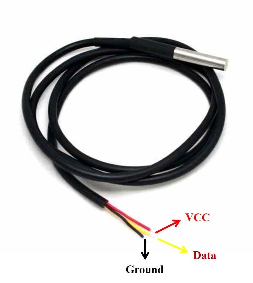
A waterproof version of this sensor is also available in the market. The following figures show the pinout of the DS18B20 sensors.
The following diagram shows the pinout of the normal DS18B20 temperature sensor.
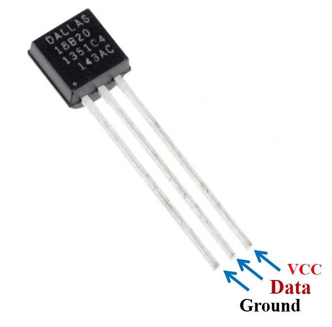
The table below lists the pin configurations:
| Pin | Description |
|---|---|
| VCC | This is the pin that powers up the sensor. It is 3.3V for ESP boards. |
| Data | This pin gives the temperature reading. |
| Ground | This pin is connected with the ground |
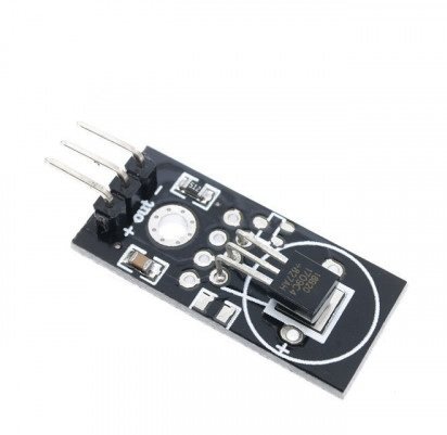
This temperature sensor also comes in a single package module which contains a sensor and a pull-up resistor. If you are using a module, you do not need to connect an external 4.7K ohm resistor. This is because the module already has an onboard pull-up resistor.
DS18S20 Applications
It have many applications. Some major applications are given below.
- industrial temperature controller
- buildings temperature controller
- digital thermometers
DS18S20 Interfacing with PIC16F877A Microcontroller
The PIC microcontroller interfaces with the DS18S20 temperature sensor through the circuit diagram, connecting the sensor to pin zero of port D. For one-wire communication, the circuit utilizes the microcontroller’s port D. Additionally, an external power supply of 5 volts is connected to the circuit for powering the sensor.
The DS18S20 obtains temperature readings, and the microcontroller connects the LCD to display these readings. The data and control lines facilitate the connection between the LCD and the microcontroller. If you want to learn more about interfacing an LCD with a PIC microcontroller, you can find comprehensive information and code examples here. This resource will guide you through setting up the LCD and displaying the temperature on its screen.

DS18S20 Interfacing with PIC Code
The code for this project is written in the MIKROC compiler. It includes sections for reading the temperature, converting the data, and displaying it on the LCD. If you do not know how to use MikroC for Pic, you can refer to these tutorials:
- How to Use “MikroC PRO for PIC” to Program PIC Microcontrollers
- Pic microcontroller programming in c using Mikroc Pro for PIC
The code interfaces with a DS18B20 temperature sensor using a PIC microcontroller to measure and display temperature in degrees Celsius. It initializes the necessary pins and configurations for both an LCD display and the DS18B20 sensor. It continuously reads temperature data from the DS18B20 by issuing commands over the one-wire interface. After obtaining the temperature data, it processes it to determine whether it’s positive or negative and whether it contains a fractional part (0.5 degrees Celsius). Finally, it displays the temperature, including the sign, integer part, and fractional part, on the LCD.
// Define LCD control pins and their directions
sbit LCD_RS at RB2_bit;
sbit LCD_EN at RB3_bit;
sbit LCD_D4 at RB4_bit;
sbit LCD_D5 at RB5_bit;
sbit LCD_D6 at RB6_bit;
sbit LCD_D7 at RB7_bit;

sbit LCD_RS_Direction at TRISB2_bit;
sbit LCD_EN_Direction at TRISB3_bit;
sbit LCD_D4_Direction at TRISB4_bit;
sbit LCD_D5_Direction at TRISB5_bit;
sbit LCD_D6_Direction at TRISB6_bit;
sbit LCD_D7_Direction at TRISB7_bit;

// Variables for temperature and display
unsigned char TempH;
unsigned char TempL;
unsigned char TLow;
unsigned char vDisp[9];
unsigned char DP;

void main() {
    // Initialize PORTB for LCD control
    PORTB = 0;
    TRISB = 0;
    // Initialize and configure the LCD
    LCD_Init();
    LCD_CMD(_LCD_CURSOR_OFF);
    LCD_CMD(_LCD_CLEAR);

    // Initialize PORTD for One-Wire communication
    PORTD = 0;
    TRISD = 0x01;

    // Wait for sensor and LCD to stabilize
    delay_ms(200);

    // Initialize vDisp for displaying temperature
    vDisp[4] = '.';
    vDisp[7] = 39; // ASCII code for the single quote (')
    vDisp[8] = 'C';

    // Display "Temp:" on the LCD
    LCD_Out(1, 1, "Temp:");

    while (1) {
        // Reset and initialize One-Wire communication
        OW_Reset(&PORTD, 0);
        OW_Write(&PORTD, 0, 0xCC); // Skip ROM Command
        OW_Write(&PORTD, 0, 0x44); // Convert_T command
        delay_ms(800); // Provide delay for conversion

        RD7_bit = ~RD7_bit; // Toggle RD7 for indication

        // Reset and initialize One-Wire communication again
        OW_Reset(&PORTD, 0);
        OW_Write(&PORTD, 0, 0xCC); // Skip ROM Command
        OW_Write(&PORTD, 0, 0xBE); // Read Scratchpad Command

        // Read temperature values
        TempL = OW_Read(&PORTD, 0); // Read Temperature low byte
        TempH = OW_Read(&PORTD, 0); // Read Temperature high byte

        // Check if temperature is integer or fractional
        DP = TempL & 0x01;

        if (TempH) { // If reading is negative
            vDisp[0] = '-';
            TempL = ((~TempL) + 1) >> 1;
        } else {
            vDisp[0] = '+';
            TempL = TempL >> 1; // Shift one position right (divide by 2) to get integer reading and remove decimal point
        }

        // Convert temperature values to ASCII characters
        vDisp[1] = (TempL / 100) + 48; // Hundreds
        vDisp[2] = ((TempL / 10) % 10) + 48; // Tens
        vDisp[3] = (TempL % 10) + 48; // Units

        // If reading is fractional (0.5 at end), set the corresponding digit
        if (DP) {
            vDisp[5] = '5';
        } else {
            vDisp[5] = '0';
        }

        // Display the temperature on the LCD
        Lcd_Chr(1, 8, vDisp[0]);
        Lcd_Chr(1, 9, vDisp[1]);
        Lcd_Chr(1, 10, vDisp[2]);
        Lcd_Chr(1, 11, vDisp[3]);
        Lcd_Chr(1, 12, vDisp[4]);
        Lcd_Chr(1, 13, vDisp[5]);
        Lcd_Chr(1, 14, vDisp[6]);
        Lcd_Chr(1, 15, vDisp[7]);
        Lcd_Chr(1, 16, vDisp[8]);
    }
}
DS18S20 temperature sensor interfacing with AVR microcontroller
The interfacing circuit diagram below shows the Lcd interfacing with avr microcontroller, which is used to display temperature on an lcd.

Code for DS18S20 with AVR microcontroller
The project code is written using Mikro C basic for AVR.
dim LCD_RS as sbit at PORTB2_bit
dim LCD_EN as sbit at PORTB3_bit
dim LCD_D4 as sbit at PORTB4_bit
dim LCD_D5 as sbit at PORTB5_bit
dim LCD_D6 as sbit at PORTB6_bit
dim LCD_D7 as sbit at PORTB7_bit

dim LCD_RS_Direction as sbit at DDB2_bit
dim LCD_EN_Direction as sbit at DDB3_bit
dim LCD_D4_Direction as sbit at DDB4_bit
dim LCD_D5_Direction as sbit at DDB5_bit
dim LCD_D6_Direction as sbit at DDB6_bit
dim LCD_D7_Direction as sbit at DDB7_bit


sub procedure ConversionDelay()
    delay_ms(800)
end sub

sub procedure StabilizeDelay()
    delay_ms(200)
end sub

dim Temperature as word
dim TempH as byte
dim TempL as byte
dim TLow as byte
dim vDisp as string[9]
dim DecimalPoint as byte

main:
     DDRC = $FE 'RC0 input for One-Wire
     LCD_Init()
     LCD_Cmd(_LCD_CURSOR_OFF) 'LCD Cursor off
     LCD_Cmd(_LCD_CLEAR) 'Clear LCD
     StabilizeDelay() 'Wait for sensor and LCD to stabilize
     vDisp = "+124.5 'C"
     LCD_Out(1, 1, "Temp:")
     while true
         OW_Reset(PORTC, 0) 'Reset command to initialize One-Wire
         OW_Write(PORTC, 0, $CC) 'Skip ROM Command
         OW_Write(PORTC, 0, $44) 'Convert_T command
         ConversionDelay() 'Provide delay for conversion
         OW_Reset(PORTC, 0) 'Reset command to initialize One-Wire
         OW_Write(PORTC, 0, $CC) 'Skip ROM Command
         OW_Write(PORTC, 0, $BE) 'Read Scratchpad Command
         Temperature = OW_Read(PORTC, 0) 'Read Temperature low byte
         Temperature = Temperature + ((OW_Read(PORTC, 0)) << 8) 'Read Temperature high byte and convert low and high bytes to one 16-bit word
         TempH = Hi(Temperature) 'High 8 bits of Temperature
         TempL = Lo(Temperature) 'Low 8 bits of Temperature
         DecimalPoint = Temperature.B0 'Check if Temperature is integer or fractional
         if (Temperature and $8000) then 'If reading is negative
            vDisp[0] = "-"
            TempL = byte((not TempL + 1) >> 1)
         else 'If reading is positive
            vDisp[0] = "+"
            TempL = TempL >> 1 'Shift one position right (divide by 2) to get integer reading and get rid of decimal point
         end if
         vDisp[1] = TempL div 100 + 48 'Get hundreds and convert to ASCII
         vDisp[2] = (TempL div 10) mod 10 + 48 'Get tens and convert to ASCII
         vDisp[3] = TempL mod 10 + 48 'Get units and convert to ASCII
         if (DecimalPoint) then 'If reading is fractional, ie has 0.5 at end
            vDisp[5] = "5"
         else 'If reading is a whole number
            vDisp[5] = "0"
         end if
         LCD_Out(1, 8, vDisp) 'Show temperature
     wend
end.
Conclusion
In conclusion, this article provided a comprehensive guide on how to interface the DS18S20 temperature sensor with both the PIC16F877A and ATmega88 AVR microcontrollers. It covered the complete circuit diagrams, code examples, and explanations for each microcontroller. The DS18S20 sensor is a versatile and programmable temperature sensor that offers the convenience of single-wire communication. Its applications range from industrial temperature control to digital thermometers. Whether you are using the PIC or AVR microcontroller, this article has provided the necessary information to successfully interface the DS18S20 and measure temperature accurately. By following the instructions and code provided, you can confidently incorporate the DS18S20 into your projects and leverage its capabilities to monitor and control temperature with ease.
You may also like to read:
- Temperature Sensor using PIC16F877A Microcontroller
- Digital Frequency Meter using Pic Microcontroller
- Soil Moisture Sensor YL-69 or HL-69 interfacing with pic microcontroller
- Digital humidity sensor using PIC microcontroller
- MQ-2 gas sensor interfacing with pic microcontroller
- Heart beat pulse sensor interfacing with pic microcontroller
- Electronic lock using pic microcontroller
Sir what does parasite power mode means?
in Parasite power mode DS18S20 gets power from microcontroller and there is no need of external power supply in this mode
sir i have a problem using the water proof sensors that is pH, turbidity and dissolved oxygen and am using the Proteus professional but i don’t get the codes for sensors i only got the DS18S20.
i will be glad if am helped for that
Sir can u send me the coding part for interfacing LM35 Temperature sensor with AT89C51 Microcontroller and displayes in the lcd.