In the field of electrical engineering, circuit breakers play a critical role in ensuring the safety and reliability of electrical systems. These devices are designed to control the flow of current through a circuit, both during normal operation and in the event of an abnormal condition. In this article, we will delve into the world of circuit breakers, exploring their functionality, components, and the principles behind their operation. Whether you are a professional in the industry or simply curious about how electrical circuits are protected, this comprehensive guide will provide you with a clear understanding of circuit breakers and their importance in maintaining electrical safety.
What is a Circuit Breaker?
A circuit breaker is a crucial electrical device used to protect electrical circuits and the devices connected to them from damage caused by excessive current flow. It is essentially a switch that can be operated manually or automatically to interrupt the flow of electricity in a circuit under certain conditions, primarily when there is an overcurrent or a fault in the circuit.
Main Function
Here are the key components and functions of a circuit breaker:

1. Switching Function: At its core, a circuit breaker acts as a switch that can be opened (turned off) or closed (turned on). It allows for the control of electrical current within a circuit.
2. Overcurrent Protection: One of the primary functions of a circuit breaker is to protect the electrical circuit from damage due to overcurrent. Overcurrent can occur during short circuits (abnormal low-resistance paths in the circuit) or overloads (when too many devices are drawing power simultaneously). When an overcurrent condition is detected, the circuit breaker will trip (open the circuit) to stop the flow of electricity, preventing further damage.
3. Fault Detection: Circuit breakers are designed to detect various types of faults, including short circuits, ground faults, and arc faults. Different types of circuit breakers are engineered to respond to specific fault conditions.
4. Manual and Automatic Operation: Circuit breakers can be manually operated by a user to disconnect or reconnect the circuit. In addition, many modern circuit breakers are equipped with automatic trip mechanisms that respond to abnormal conditions without human intervention.
5. Resettable: Unlike fuses, which need to be replaced after they trip, circuit breakers are resettable. Once the cause of the overcurrent or fault is resolved, the circuit breaker can be manually reset to restore power to the circuit.
6. Ratings: Circuit breakers are rated for specific current-carrying capacities, voltage levels, and interrupting capacities. These ratings ensure that the circuit breaker can handle the electrical load and protect the circuit under normal and fault conditions.
7. Types: There are various types of circuit breakers, including thermal-magnetic circuit breakers, electronic circuit breakers, and digital circuit breakers. Each type employs different technologies to provide protection and control features suitable for different applications.
8. Arc Interruption: In addition to stopping the flow of current, circuit breakers are designed to safely interrupt electrical arcs that may form during a fault. Arc interruption is crucial for preventing fires and ensuring user safety.
Circuit breakers are commonly used in residential, commercial, and industrial electrical systems to ensure the safe and reliable operation of electrical circuits. They play a critical role in preventing electrical fires, protecting equipment, and minimizing downtime due to electrical faults.
How does Circuit Breaker work?
Basically, a circuit breaker consists of a fixed and a moving contact. If there is a single set of fixed and moving coils, and the circuit breaker is connected in a single phase, then it is called a single-pole circuit breaker. Similarly, different-pole circuit breakers exist, depending on the number of sets of fixed and moving contacts.
Each pole consists of an arc extinguishing chamber. If the arc is not extinguished, the contacts can become welded together. The arc can be extinguished by any insulating medium such as air, dielectric oil, SF6, vacuum, etc. The contacts remain closed during normal conditions and are opened when a fault occurs.
Components of a Circuit Breaker
A circuit breaker consists of several essential components, including:
- Fixed Contact: This is a stationary part of the circuit breaker that remains in a fixed position.
- Moving Contact: The moving contact is designed to pivot or move away from the fixed contact, thereby creating a gap between the contacts.
- Coils: Coils are electromagnetic components that generate magnetic fields when an electric current passes through them. These coils play a crucial role in the operation of the circuit breaker.
Single-Pole Circuit Breaker
In a single-pole circuit breaker configuration, there is only one set of fixed and moving contacts, and the circuit breaker is designed to handle a single phase of an electrical system. Here’s how it works:
- Normal Operating Condition:
- During normal operating conditions, the circuit breaker is in its closed position. The moving contact is in contact with the fixed contact, allowing the electrical current to flow through the circuit breaker without interruption.
- Abnormal Condition – Overcurrent or Fault:
- If an overcurrent situation occurs due to an overload or a short circuit in the electrical circuit connected to the breaker, the current passing through the coils generates a magnetic field.
- This magnetic field exerts a force on the moving contact, causing it to pivot away from the fixed contact. This action opens the circuit and interrupts the flow of electricity.
- Tripped/Open Position:
- Once the moving contact is separated from the fixed contact, the circuit is open, and the electrical current is stopped from flowing through the circuit breaker.
- This interruption prevents further damage caused by the excessive current flow, such as equipment damage or overheating.
- Reset and Closing the Circuit:
- After the underlying issue causing the overcurrent condition is resolved, the circuit breaker can be manually reset.
- When reset, the moving contact is brought back into contact with the fixed contact, restoring the closed position of the circuit breaker.
- The circuit is once again complete, allowing the normal flow of current through the breaker.
Multi-Pole Circuit Breakers
The concept of multiple sets of fixed and moving contacts extends to multi-pole circuit breakers, where each pole corresponds to a different phase in a multi-phase electrical system. These circuit breakers are designed to handle the complexities of multi-phase power distribution systems and offer enhanced protection and control.
In summary, a circuit breaker’s working involves the interaction between fixed and moving contacts, along with the influence of coils that generate magnetic fields. This interplay allows the circuit breaker to automatically open and interrupt the electrical circuit when abnormal conditions, such as overcurrents or faults, are detected. This protective mechanism helps prevent damage to equipment and ensures the safety and reliability of the electrical system
A control circuit of a circuit breaker is shown in the figure:
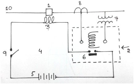
The numbered parts in the figure are:
- Circuit breaker
- Trip circuit
- Trip coil
- Protected line
- Battery
- Realy contacts
- Potential transformer
- Current transformer
- Switch
Principle Operation of a Circuit Breaker
The principle of operation of a circuit breaker can be explained as follows:
The contacts of the circuit breaker remain closed during normal conditions and are opened when a fault occurs. When a fault occurs in a system, the trip coil of the breaker energizes, and the moving contacts are separated through a mechanism. During separation, an arc is produced between the contacts, which must be extinguished in order to stop the flow of current.
Arc Initiation
When the current-carrying contacts are separated, an arc is produced between them. The figure demonstrates the closed and open contacts. When the contacts are closed, there is a high current density, high resistance, and high thermal pressure at the terminals. When the contacts are opened, the pressure decreases and the surrounding air becomes ionized. The current continues to flow between the contacts as long as the medium is not deionized.

Arc Extinction Methods
Two methods are used for the arc extinction:
- High resistance method.
- Current zero method
- HIGH RESISTANCE METHOD
1. High Resistance Method
In this method, the resistance of the path is increased so that the arc is extinguished. But it requires a lot of energy due to which it is only used in low-capacity AC or DC circuit breakers.
Resistance can be increased by the following methods:
a. Lengthening the arc:
The distance between the contacts is increased. Arc runners or arc splitters are also used for this purpose.
b. Cooling the arc:
Fans provide the cooling air which cools down the arc and de-ionizes the medium.
c. Reducing X-sectional area of the arc:
Reducing the x-sectional area of the arc increases the resistance of the path and extinguishes the arc.
d. Splitting the arc:
Arc is split by adding conducting plates perpendicular to the arc. These plates are called splitters. The process of extinguishing the arc is shown in the figure:

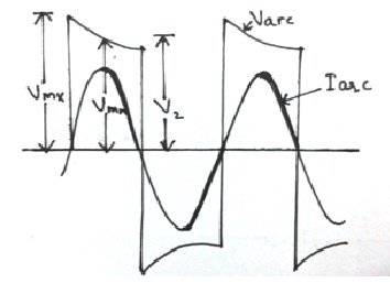
2. Low Resistance or Current Zero Method
This method is used in high-power circuit breakers. In an AC system, after every half cycle, the current reduces to zero. The insulating oil or gas flows between the contacts and deionizes the medium, due to which the arc diminishes. The AC arc waveform is shown in the figure:
Magnitude of arc
The electric discharge between any two points is known as an arc. Electric discharge consists of a number of charge carriers. The amount of these charge carriers depends on:
- Potential difference between the contacts.
- Dielectric strength of insulating medium.
- Current produced due to discharge.
- Length of the arc.
- Diameter of the arc.
The arc current and voltage are given by:
Varc= A+ Bd+ (C+Dd/Iarc)
Where d= length of arc
Varc= voltage drop in arc
Iarc= arc current
A,B,C,D= constants
And the arc energy can be found by
E=Varc x Iarc x t
Recovery Voltage
The voltage across the contacts at normal frequency is known as recovery voltage. This voltage is the same as the system voltage. When the arc is extinguished and the current flow stops, a transient voltage appears across the contacts. However, this voltage is quickly diminished due to the damping effect of the resistance, and the normal circuit voltage appears across the contacts, which is called the recovery voltage.
Restriking Voltage
The transient voltage that appears across the contacts at the time the arc is extinguished is known as the restriking voltage. After the extinction of the arc, the voltage tends to increase in the opposite direction and reach the value where the arc can strike again. This voltage is called the restriking voltage.
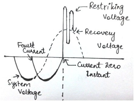
If the dielectric strength of the medium increases more rapidly as compared to the restriking voltage then the current flow stops. The waveform of the restriking voltage is shown in the figure above.
Conclusion
In conclusion, circuit breakers are vital components in electrical engineering that protect electrical circuits and devices from damage caused by excessive current flow. They have several key functions, including overcurrent protection, fault detection, and manual or automatic operation. Circuit breakers play a critical role in maintaining electrical safety by interrupting the flow of electricity when abnormal conditions are detected. They are resettable and have specific ratings to ensure reliable operation. Different types of circuit breakers are used in various applications, and they are designed not only to stop the current but also to safely interrupt electrical arcs. Understanding how circuit breakers work and the principles behind their operation is essential for maintaining the safety and reliability of electrical systems in residential, commercial, and industrial settings.
Related content:
please confirm the numbering of the labelled parts in the circuit breaker schematic diagram corresponds with their names listed below it.
Sorry there was a mistake in ordering of labels for circuit breaker. Check now it has been updated
i find this very helpful and easy to understand