Transformer less power supply for microcontrollers, in this article you will learn how to design transformer less power. Applications of Transformer less power supply. Cost analysis of commonly used power supplies and transformer less power supplies.
Applications of Transformer less power supply:
Transformer less power supply is suitable only for low power applications. For example microcontrollers based circuits require 5 volt power supply and maximum current required for these microcontrollers based circuits are not more than 20-30mA. So power supply of rating 30m x 5 = 1.5 watt is commonly required for microcontroller based circuits. Transformer less power supplies are also used in low cost emergency lights and mobile chargers.
Why transformer less supply is better for microcontrollers?
Commonly used power supplies require step down transformer to step down 220/120 AC voltage to low required voltage. This low voltage is then rectified using rectifier circuit. After that voltage regulator is used to produce regulated voltage from rectified voltage. Such power supplies are useful for high power applications. But these power supplies are costly for low power applications i.e. microcontroller based circuits. Transformer less power supply can be made in very low cost and it is also very small in size. Cost of transformer less power supply for microcontrollers is almost 5 times less than power supply having step down transformer.

Description of Transformer less power supply :
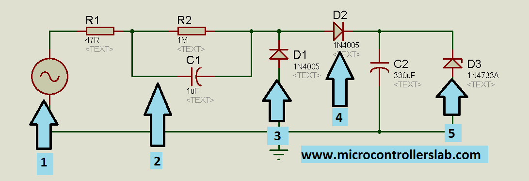
Circuit diagram of transformer less power supply for microcontrollers is shown below. I have used numbering labels to explain each component and functionality of each component used in this circuit.
- Label 1 is AC voltage input. It can be either 220 volt AC input or 120 volt AC input. Its depend on voltage selection of your country provided by power company.
- Label 2 have most important function in transformer less power supplies. Label two consists of two resistor and one capacitor. As you know that it is the basic concept of physics that when capacitor and resistor connected in series it does not allow current to flow above certain limit. In other words, resistor or capacitor combination in series can be used to make constant current source . But the condition is reactance of capacitor should be much greater than resistance. In diagram shown below, resistor R1 and capacitor C1 serve the purpose of constant current source. Resistor R2 have high resistance. Maximum voltage will drop across this resistor. So label two will allow only constant current and required voltage for next stage.
- Lable 3 is a diode which is used as a free wheeling diode.
- Label 4 is a diode which is used as a rectifier diode which is used to convert AC voltage into DC. Only half wave rectification is used in this circuit. After rectifier diode, a capacitor is used to remove AC components from rectified voltage.
- Label 5 is a 5 volt zener diode which is used as a voltage regulator to maintain 5 volt constant output. Because tranformer less power supply is designed for microcontrollers and microcontrollers usually operate at 5 voltage.
- circuit diagram of tranfromerless power supply
circuit diagram of transformer less power supply :
- Complete circuit diagram of circuit diagram of tranfromerless power supply is given below :

Schematic of transformerless power supply If you have any issue after reading this article and anything is not clear about above circuit, you can ask by commenting on this post. Share this post with others by clicking below social sharing buttons. Thanks 🙂
hello malik,
can explain me the label 2 and with analitics expression please
hi
Tanks for sharring 🙂
it’s a suit realisation, but it’s for a low amount (few mA). One other thing, if the source is the power supply 220 V there is a risk for electrocution hazard.
and for 120VAC too!!!
calculation?
Hi Bilal,
Thanks for this masterpiece. In addition to the safety issues raised by other readers above, I wished you had stated clearly the electrical ratings of the components.
For instance, first the resistor in the cct diagram has no wattage stated. This could pose serious safety hazards to inexperienced hobbyists.
Please help by providing these information.
Thanks.
Yusuf
What is the purpose of free wheeling diode D1 in this circuit, even without the diode D1 circuit works the same. There is no inductor for back EMF, So no need D1 as per my knowledge, can you please explain this
IS THE CAPACITOR NO 1 SHOULD BE AN AC CAPACITOR RATHER THAN DC CAPACITOR