In this Arduino project, we will create a web server that will control the angle of a servo motor. We will develop a small webpage using HTML and JavaScript and then send command to Arduino using the Wi-Fi module. We will make the connection between the webpage and Wi-Fi module using IP address. By using a slider we will control angle of Motor. If we set the port forwarding for our Wi-Fi router we can control the motor from anywhere in world. You can search on the internet for port forwarding settings for your router.
Arduino Uno R3 does not support Wi-Fi capabilities hence we have to use a separate Wi-Fi module to enable Wi-Fi connectivity. Therefore, we will interface and program ESP-01 Wi-Fi module with Arduino to enable Wi-Fi features. We will use Arduino IDE to program our Arduino with ESP-01 and servo motor. AT commands through the serial port that is UART will be used to configure the ESP-01 Wi-Fi module.
Recommended Reading: Interface Arduino with esp8266 WI-FI module


Arduino Web Controlled Servo Motor Overview
We will require the following components for this project.
Required Components:
- Arduino Uno: We will use Arduino due to its easy use. It also provides several digital pins to interface with the servo motor and ESP8266 Wi-Fi module at the same time. It is very friendly when you prototyping any project.
- ESP8266 Wi-Fi Module: ESP8266 is a Wi-Fi chip that provides Transfer Control Protocol (TCP) and Internet Protocol (IP). There are different ESP8266 modules available in the market. In this project, we will use ESP-01. It has 6 pins and operates on 3.3v.
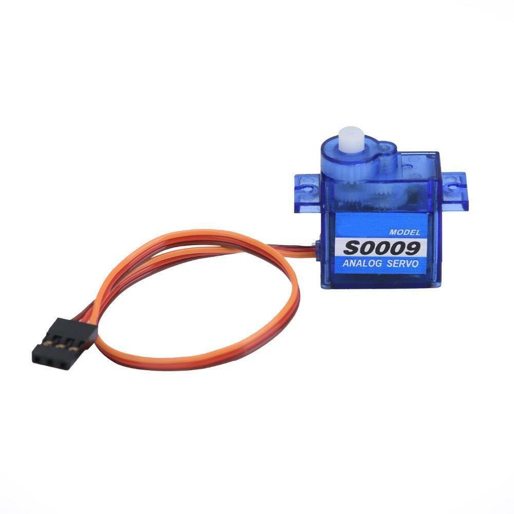
- SG-90 Servo Motor: SG90 is a low cost and high output power servo motor. It is small enough that it can easily fit into your robotics ARM or obstacle avoidance robotics projects.
- One 2k resistor
- One 1k resistor
- Jumper wires
Our servo control web server will look something like this:
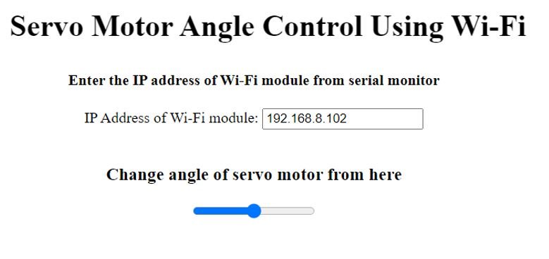
When we will upload the Arduino sketch to our board, the ESP8266 will initialize and connect with the local Wi-Fi that we will set in the code. We will also obtain the IP address of the ESP8266 in the serial monitor. We will enter this IP address in our web server. Then we will move the slider to vary the angle of the servo arm. Through the slider, we will be able to control the servo arm.
Connection Diagram of Arduino Web Controlled Servo Motor
This section will explain the connections of the various components specified above with Arduino Uno to form the web controlled servo motor project.

Let us discuss them one by one.
Arduino with ESP-01
The ESP-01 module consists of 8 pins. The diagram below shows its pinout.
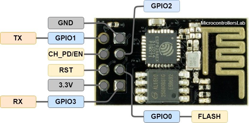
However, we will use 5 of these pins to connect with Arduino. These include the VCC, EN, GND, RX, and TX pins.
The table below shows the connections that we will use to connect the two devices:
| ESP-01 | Arduino UNO |
|---|---|
| VCC | 3.3V |
| EN | 3.3V |
| GND | GND |
| TX | Pin 6 |
| RX | Connect RX of ESP-01 with middle point (Junction point of series 1k and 2k resistor) of Voltage divider. The second end of 1k resistor with Pin7 of Arduino. The second end of 2k resistor with GND pin of Arduino. |
Arduino with Servo Motor
SG90 is a low cost and high output power servo motor. It can rotate up to 180 degrees and each step can be of maximum 90 degrees. Moreover, it is small enough that it can easily fit into your robotics ARM or obstacle avoidance robotics projects. On top of that, it requires only one output pulse signal to control its movement.
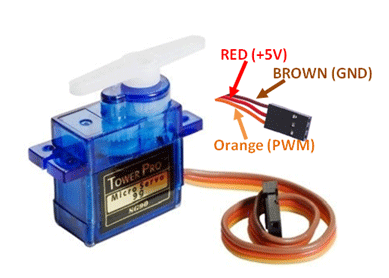
The following figure shows the pinout diagram of SG90 servo motor. It consists of three pins only such as PWM, ground and Vcc pin. Brown, orange and red wires are GND, Vcc and PWM pins respectively. Details and functionality of each pin is listed in the next section.
Pin Configuration Details
Vcc and ground, as their name suggests, are the power supply pins which are used to power servo motor. Only 5 volts of power signal is required to power this motor. Mostly microcontrollers or development boards have onboard 5 volts supply which we can use to power SG90 servos.
This table briefly describes all three pins:
| Wire of motor | Possible colors of each wire |
|---|---|
| VCC pin | Red |
| GND pin | Black, or brown |
| Control Signal / PWM pin | Yellow, orange, or white |
Connections of Servo motor with Arduino are as follows:
| Servo Motor | Arduino |
| VCC pin | 5V |
| GND pin | GND |
| Control Signal | Pin 10 |
Web Controlled Servo Motor Code
The software part for this project consists of two parts. The HTML page and the Arduino code which is placed in IDE and are uploaded to the board. We will use Arduino IDE to program our Arduino board.
HTML Page
First, you need to make an .html page which will form your website to control the Motor angle. Open notepad and copy the code given below. Save it as a .html extension for it to work properly.
<!DOCTYPE html >
<html>

<head>
<title>Servo Motor Angle Control Using Wi-Fi</title>
<script src="jquery.js"></script>
</head>

<body>
	<center>
<h1>
	<marquee loop="infinite" direction="left">
	<b> Servo Motor Angle Control Using Wi-Fi </b>
	</marquee>
</h1>
<h4> <b> Enter the IP address of Wi-Fi module from serial monitor</b> </h4>
<div style="margin: 0; width:600px; height:40px;">
	<FORM NAME="form" ACTION="" METHOD="GET">
		IP Address of Wi-Fi module:
		<INPUT TYPE="text" NAME="inputbox" VALUE="192.168.8.102">
	</FORM>
</div>
<h3> Change angle of servo motor from here</h3>
<center><input type="range" min="0" max="180" onmouseup="servo(this.value)" /></center>
	</center>
</body>

<script>
$.ajaxSetup({timeout:1000});
function servo(angle)
{
	TextVar = form.inputbox.value;
	ArduinoVar = "http://" + TextVar + ":80";
	$.get( ArduinoVar, { "ang": angle })	;
	{Connection: close};
}
</script>

</html>
<body></body> What ever written inside the body tag will displayed on the page of website. Different tags are used inside the body tag to make the display attractive and readable.
<center></center> tag is used to bring the text in the center of page
<h1></h1> is used to make the size larger. There are h2, h3, h4, h5 tags which differ in text size.
<marquee></marquee> is used to move the text in specified direction as mentioned in attribute “direction”.
<b><\b> makes the text bold.
<div></div> is used to make a box of specified height and width. Border is not shown for it .
<FORM></FORM> is used to take input from user.
<input type= “range”> creates a slider whose range can be specified in attributes of tags.
Function servo sends the value of slider to board so that it can move the servo to a specified angle and at the end it closes the connection.
jquery.js
You will also need jQuery file for the web page. Both should be placed in the same folder.
Arduino Sketch
Open your Arduino IDE and go to File > New to open a new file. Copy the code given below in that file and save it.
#include <SoftwareSerial.h>       //Including the software serial library
#include <Servo.h>                //including the servo library

#define servopin 10            //connect servo on pin9
#define DEBUG true                //To display Wi-Fi module messages on serail monitor
SoftwareSerial esp(6, 7);      //defining communication pin Tx and Rx
Servo serMtr;                     //Servo Motor Variable


int strPos = 0;    //Starting Position
int minPos = 0; //minimum position
int maxPos = 180; //max position

void setup()
{
  serMtr.attach(servopin);
  serMtr.write(maxPos);
  serMtr.detach();
  Serial.begin(9600); //starting serial Monitor
  esp.begin(9600); //Starting Wi-Fi module

  sendData("AT+RST\r\n", 2000, DEBUG);                      //Reset module
  sendData("AT+CWMODE=1\r\n", 1000, DEBUG);                 //Set the Wi-Fi module in station mode
  sendData("AT+CWJAP=\"Microcontrollerslab.com\",\"itulahore786\"\r\n", 2000, DEBUG);   //Connect to Wi-Fi Router.
  while(!esp.find("OK"))
  {
    //wait for Wi-Fi Module to get connected with Router
  }
  sendData("AT+CIFSR\r\n", 1000, DEBUG);          //Showing IP address on the serial monitor
  sendData("AT+CIPMUX=1\r\n", 1000, DEBUG);       //Allowing multiple connections
  sendData("AT+CIPSERVER=1,80\r\n", 1000, DEBUG); //Starting the web server on port 80
}

void loop()
{
  if (esp.available())     //checking data availability on module
  {
    if (esp.find("+IPD,")) //if new command is available
    {
      String show;
      esp.find("?");                           //run cursor until command is found
      show = esp.readStringUntil(' ');         //get or read message
      String com = show.substring(0, 3);    //command is stored in the first 3 characters "ang"
      String valStr = show.substring(4);      //next 4 characters give the angle value
      int val = valStr.toInt();            //convert to integer
      if (DEBUG)
      {
        Serial.println(com);
        Serial.println(val);
      }
      delay(100);
      //move Motor to given angle
      if(com == "ang")
      {
         //checking max and min position of angle
         if (val >= maxPos)
         {
           val = maxPos;
         }
         if (val <= minPos)
         {
           val = minPos;
         }
         serMtr.attach(servopin); //attach servo Motor to Servo library
         while(strPos != val)
         {
           if (strPos > val)
           {
             strPos -= 1;
             serMtr.write(strPos);
             delay(10);
           }
           if (strPos < val) {
             strPos += 1;
             serMtr.write(strPos);
             delay(10);
           }
         }
         serMtr.detach(); //deatch the servo
      }
  }
 }
}
String sendData(String com, const int tOut, boolean debug)//function to send data
{
  String res = "";
  esp.print(com);
  long int time = millis();
  while ( (time + tOut) > millis())
  {
    while (esp.available())
    {
      char c = esp.read();
      res += c;
    }
  }
  if (debug)
  {
    Serial.print(res);
  }
  return res;
}
How does the Code Work?
We will start by including all the necessary libraries required for this project as shown below. We will include the built-in Servo.h library for easy servo motor functionalities. Additionally, we will require SoftwareSerial.h as well to allow serial communication on the digital pins of Arduino that we will be using as Tx and Rx.
#include <SoftwareSerial.h>       //Including the software serial library
#include <Servo.h>                //including the servo library
Next, define the Arduino pin that is connected with the control signal pin of the servo motor. In our case, we are using digital pin 10.
#define servopin 10 Moreover, define another DEBUG and set it as true. This will help us show the ESP-01 messages on the serial monitor.
#define DEBUG trueThe following line defines the serial communication Tx pin as Arduino pin 6 and Rx as Arduino pin 7.
SoftwareSerial esp(6, 7); Moreover we will create an object of the Servo library called ‘serMtr.’ You can use any other name as you like.
Servo serMtr;The following int variables set the starting, minimum and maximum positions of the servo arm. Note that the servo arm moves from 0-180 degrees.
int strPos = 0;    //Starting Position
int minPos = 0; //minimum position
int maxPos = 180; //max position
setup()
Inside the setup() function, first attach the signal pin with the servo object.
serMtr.attach(servopin);Next, we will move the servo motor’s arm 180 degrees (maximum position) by using the write() method on the servo object. Here we are passing the ‘maxPos’ variable as a parameter inside this function. Note that the ‘maxPos’ variable holds the value 180.
serMtr.write(maxPos);Then detach the motor so that it can work according to void loop() function.
serMtr.detach();Open the serial communication at a baud rate of 9600 for both the serial monitor and ESP8266.
Serial.begin(9600); //starting serial Monitor
esp.begin(9600); //Starting Wi-Fi module
Next, we will use AT commands to first connect ESP-01 with the local Wi-Fi. After a successful connection has been established, we will obtain the IP address that will help us access the web server.
  sendData("AT+RST\r\n", 2000, DEBUG);                      //Reset module
  sendData("AT+CWMODE=1\r\n", 1000, DEBUG);                 //Set the Wi-Fi module in station mode
  sendData("AT+CWJAP=\"Microcontrollerslab.com\",\"itulahore786\"\r\n", 2000, DEBUG);   //Connect to Wi-Fi Router.
  while(!esp.find("OK"))
  {
    //wait for Wi-Fi Module to get connected with Router
  }
  sendData("AT+CIFSR\r\n", 1000, DEBUG);          //Showing IP address on the serial monitor
  sendData("AT+CIPMUX=1\r\n", 1000, DEBUG);       //Allowing multiple connections
  sendData("AT+CIPSERVER=1,80\r\n", 1000, DEBUG); //Starting the web server on port 80
These are the series of AT commands that we use to initialize the ESP8266 Wi-Fi module.
AT+RST: This type of command is used for reset the Wi-Fi module when it is in working condition. The response would be ok, when reset the module.
sendData("AT+RST\r\n", 2000, DEBUG); //Reset moduleAT+CWMODE=1 : This sets the Wi-Fi mode of ESP8266 in this case in station mode.
sendData("AT+CWMODE=1\r\n", 1000, DEBUG); AT+CWJAP=”SSID”,”PASSWORD” : This connects the ESP8266 with an AP whose SSID and password are given.
sendData("AT+CWJAP=\"Microcontrollerslab.com\",\"itulahore786\"\r\n", 2000, DEBUG);AT+CIFSR: This command obtains the local IP address.
sendData("AT+CIFSR\r\n", 1000, DEBUG);AT+CIPMUX=1:This command is used to enable multiple connections (maximum 4)
sendData("AT+CIPMUX=1\r\n", 1000, DEBUG);AT+CIPSERVER=1: This command configures ESP8266 as a server.
sendData("AT+CIPSERVER=1,80\r\n", 1000, DEBUG);sendData()
We use the following sendData() function to send the data to the Wi-Fi module. It takes in three parameters. The first is the command, the second is the timeout which is the delay and the third is debug.
String sendData(String com, const int tOut, boolean debug)//function to send data
{
  String res = "";
  esp.print(com);
  long int time = millis();
  while ( (time + tOut) > millis())
  {
    while (esp.available())
    {
      char c = esp.read();
      res += c;
    }
  }
  if (debug)
  {
    Serial.print(res);
  }
  return res;
}
loop()
In the loop() function, the Wi-Fi module will check if the data is arrived or not. If the data is arrived then it will read this data and will show it on the serial monitor and move the Motor accordingly.
void loop()
{
  if (esp.available())     //checking data availability on module
  {
    if (esp.find("+IPD,")) //if new command is available
    {
      String show;
      esp.find("?");                           //run cursor until command is found
      show = esp.readStringUntil(' ');         //get or read message
      String com = show.substring(0, 3);    //command is stored in the first 3 characters "ang"
      String valStr = show.substring(4);      //next 4 characters give the angle value
      int val = valStr.toInt();            //convert to integer
      if (DEBUG)
      {
        Serial.println(com);
        Serial.println(val);
      }
      delay(100);
      //move Motor to given angle
      if(com == "ang")
      {
         //checking max and min position of angle
         if (val >= maxPos)
         {
           val = maxPos;
         }
         if (val <= minPos)
         {
           val = minPos;
         }
         serMtr.attach(servopin); //attach servo Motor to Servo library
         while(strPos != val)
         {
           if (strPos > val)
           {
             strPos -= 1;
             serMtr.write(strPos);
             delay(10);
           }
           if (strPos < val) {
             strPos += 1;
             serMtr.write(strPos);
             delay(10);
           }
         }
         serMtr.detach(); //deatch the servo
      }
  }
 }
}
Demonstration
Make sure you choose the correct board and COM port before uploading your code to the board. Go to Tools > Board and select Arduino UNO. Next, go to Tools > Port and select the appropriate port through which your board is connected.

Click on the upload button to upload the code to the board.
After you have uploaded your code to the development board, open the serial monitor and set the baud rate to 9600. In a few moments, the Wi-Fi will get connected and you will receive an IP address.

Now open html file that we created in a web browser. The web server will open up. Enter the IP address that you obtained in the serial monitor. Now move the slider and the servo motor will move accordingly.

Watch the video demonstration below:
You may also like to read:
- ESP32 Web Server Control Servo motor with Arduino IDE
- Servo Motor with Raspberry Pi Pico using MicroPython
- Arduino L293D Motor Driver Shield Control DC, Servo, and Stepper Motors
- Interface MG995 Servo Motor with Arduino – Example Code
- CCPM Servo Consistency Master/Servo Motor Tester
- SG-90 Servo Motor Interfacing with TM4C123 Launchpad
- servo motor interfacing with 8051 using Keil compiler
- Joystick based servo motor control using Arduino
- Servo motor control and interfacing with Arduino
Hi, where i can find the code? Tank you!
I want know how to control servo motor with arduino uno , nodemcu 8266 through any android app
How I find the code?