Ac current measurement using acs712 hall effect current sensor and Arduino. In this tutorial, you will learn how to design alternating current measurement system using acs712 hall effect current sensor and Arduino Uno R3. But you can apply same concept to Arduino mega, pic microcontroller, 8051 microcontroller or avr microcontroller. you just need make change in code but the rest of the concept will remain same. In my last tutorial, I have shown how to measure dc current using acs712 current sensor. In that tutorial, I have also explained introduction to acs712 hall effect current sensor, working of current sensor and how to measure current from hall effect sensor. I will apply same concepts in this article to measure ac current with acs712 hall effect current sensor. you may also like to read how to measure ac voltage using Arduino.
How to measure ac current with acs712 hall effect current sensor
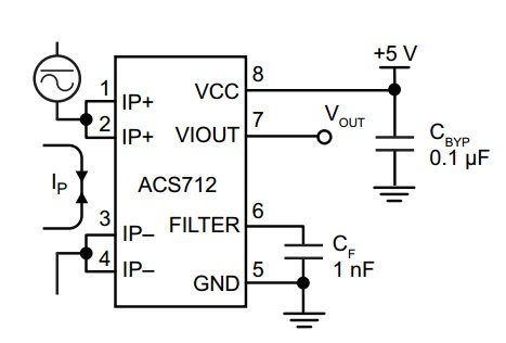
As I have discussed in my last article, acs712 current sensor converts input current into proportional voltage depending on nature of the input current. If input current is dc, the output voltage of current sensor will be dc also. if input current to current sensor is ac, the output voltage of current sensor will be also alternating voltage. Shape of output voltage depend on the shape of input current. if shape of input current is sine wave, then the shape of output voltage will be also sine wave which is usually happens in case of ac current. The pin out of hall effect current sensor is given below.
so we will get sine wave at the output of hall effect sensor. So we need a method to measure peak of sine wave and then we can convert this peak voltage back into rms voltage by simply multiplying it with square root of 2 which is the relationship between peak value and rms value of voltage. I have explained it more details in my last article on interfacing of acs712 hall effect current sensor with Arduino. I recommend you to read it first, if you want to understand, how to measure this output voltage and how to convert this output voltage back into current using Arduino.

Ac load interfacing with acs712 hall effect current sensor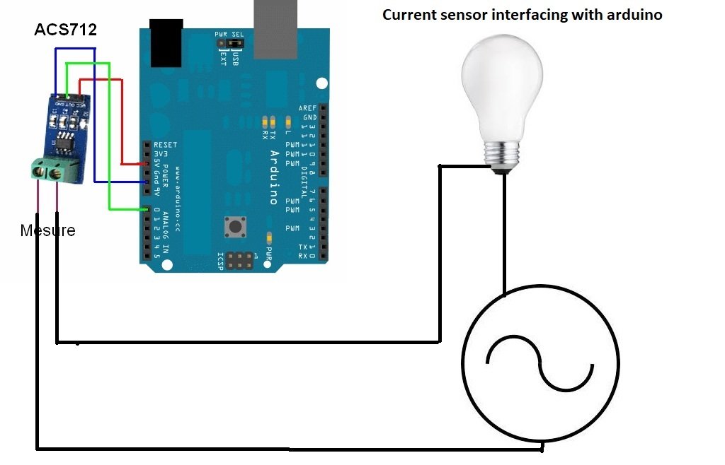
Ac current measurement using acs712 current sensor and Arduino
Circuit diagram for ac current measurement using acs712 current and Arduino is given below:

Code for ac current measurement using acs712 current sensor
// include the library code:
#include <LiquidCrystal.h> //library for LCD

// initialize the library with the numbers of the interface pins
LiquidCrystal lcd(8, 9, 10, 11, 12, 13);

//Measuring Current Using ACS712

const int analogchannel = 0; //Connect current sensor with A0 of Arduino
int sensitivity = 185; // use 100 for 20A Module and 66 for 30A Module
float adcvalue= 0;
int offsetvoltage = 2500;
double Voltage = 0; //voltage measuring
double ecurrent = 0;// Current measuring

void setup() {
 //baud rate
 Serial.begin(9600);//baud rate at which arduino communicates with Laptop/PC
 // set up the LCD's number of columns and rows:
 lcd.begin(20, 4); //LCD order
 // Print a message to the LCD.
 lcd.setCursor(1,1);//Setting cursor on LCD
 lcd.print("MICROCONTROLLERSLAB");//Prints on the LCD
 lcd.setCursor(4,2);
 lcd.print(".com");
 delay(3000);//time delay for 3 sec
 lcd.clear();//clearing the LCD display
 lcd.display();//Turning on the display again
 lcd.setCursor(1,0);//setting LCD cursor
 lcd.print("Reading Values from");//prints on LCD
 lcd.setCursor(1,1);
 lcd.print("DC Current Sensor");
 lcd.setCursor(5,2);
 lcd.print("ACS 712");
 delay(2000);//delay for 2 sec
}

void loop() //method to run the source code repeatedly
{
 unsigned int temp=0;
 float maxpoint = 0;
 int i=0;
 for(i=0;i<500;i++)
 {
 if(temp = analogRead(analogchannel),temp>maxpoint)
 {
 maxpoint = temp;
 }
 }
 adcvalue = maxpoint;
 Voltage = (adcvalue / 1024.0) * 5000; // Gets you mV
 ecurrent = ((Voltage - offsetvoltage) / sensitivity);
 ecurrent = ( ecurrent ) / ( sqrt(2) );
//Prints on the serial port
 Serial.print("Raw Value = " ); // prints on the serial monitor
 Serial.print(adcvalue); //prints the results on the serial monitor

 lcd.clear();//clears the display of LCD
 delay(1000);//delay of 1 sec
 lcd.display();
 lcd.setCursor(1,0);
 lcd.print("adc Value = ");
 lcd.setCursor(13,0);
 lcd.print(adcvalue);

 Serial.print("\t mV = "); // shows the voltage measured
 Serial.print(Voltage,3); // the '3' after voltage allows you to display 3 digits after decimal point

 lcd.setCursor(1,1);
 lcd.print("Voltage = ");
 lcd.setCursor(11,1);
 lcd.print(Voltage,3);
 lcd.setCursor(17,1);
 lcd.print("mV");//Unit for the voltages to be measured

 Serial.print("\t ecurrent = "); // shows the voltage measured
 Serial.println(ecurrent,3);// the '3' after voltage allows you to display 3 digits after decimal point

 lcd.setCursor(1,2);
 lcd.print("ac Current = ");
 lcd.setCursor(11,2);
 lcd.print(ecurrent,3);
 lcd.setCursor(16,2);
 lcd.print("A"); //unit for the current to be measured
 delay(2500); //delay of 2.5 sec
}
In above code, I have taken 500 samples of output voltage of current sensor and detect the peak value of sine wave. After detecting peak value of voltage, it is converted back into current using the sensitivity formula given in code.
AC Current Measurement with ACS712 Sensor Module and Arduino
In this tutorial, you will learn how to design alternating current measurement system using ACS712 hall effect current sensor module and Arduino Uno R3. The same concept is applicable to Arduino mega, pic microcontroller, 8051 microcontroller or avr microcontroller as well. Firstly, we will introduce you to the ACS712 hall effect current sensor module including its working and how to measure current from it. Then we will interface it with Arduino UNO and design our project of AC current measurement.
You can also have a look at our previous tutorial, where we looked at how to measure dc current using acs712 current sensor.
You may also like to read how to measure ac voltage using Arduino.
Introduction to ACS712 Current Sensor Module
The ACS712 is a hall effect based current sensor. It can measure both direct current and alternating current. It is a linear type sensor. This is very a famous integrated circuit designed by Allegro. It has features of noise cancellation and has a very high response time. Output error is about 1.5 percent but it can be tackled with some intelligent programming and multiplying measured value with standard error of sensor. If you give dc current to its input, it will give proportional dc voltage at the output of sensor and if you give ac current at the input, it will give you proportional ac voltage at the output. Proportional term depends on the output sensitivity of the sensor.
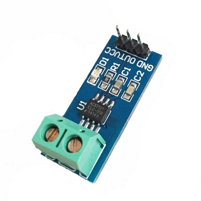
The ACS712 current sensing module features the ACS712 IC to measure DC/AC current using the Hall Effect principle. It is easy to use with microcontrollers such as Arduino as it uses only three pins out of which two are power supply pins and the other is the analog output pin. The analog output pin gives readings in the range of 0-5V, according to the current flow.
Types of ACS712 current sensor modules
There are three types of ACS712 sensor modules available according to current rating (5A, 20A and 30A) of the ACS712 sensor. Below table provides the rating and all the details of three types of ACS712 hall effect sensors.
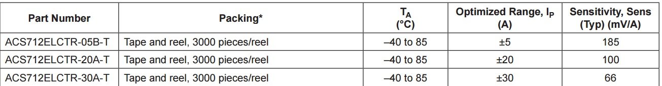
- ACS712ELCTR-05B: This sensor can measure current in the range of plus minus 5A and output sensitivity is 185mv/A . This means that the output voltage which will appear at the output pin of current sensor is 185 mV for every ampere passes through hall effect sensor. Similarly for other sensors but sensitivity is different for them.
- ACS712ELCTR-20A-T : It can measure 20 and -20 ampere current very easily and output sensitivity is 100mv/A.
- ACS712ELCTR-30A-T : It can measure 30 and -30 ampere current very easily and output sensitivity is 66mv/A.
Note: The ACS712 sensor has a voltage offset of VCC/2. This means that if you supply 5V to the module with no load at the output, then the output will be 5/2=2.5V. Therefore, the following formula gives the relationship between output voltage and supply voltage:
Output Voltage = VCC/2 + Sensitivity*input current
For example if using ACS712 sensor module with 5A and supply voltage of 5V then:
Output Voltage = 2.5 + 188*input current
How does an ACS712 current sensor work?
This ACS712 sensor consists of a linear hall effect circuit along with copper conduction path. Copper conduction path is located around the surface of the die. When ac or dc current passes through a copper conduction path, it produces a magnetic field. This electromagnetic field interacts with hall effect sensor. Hall effect circuit converts this electromagnetic field into proportional voltage either ac or dc depending on the input current type. This output voltage is measured with the help of Arduino or any microcontroller. After measuring this voltage, we convert it back into current using the equation discussed above.
Pinout
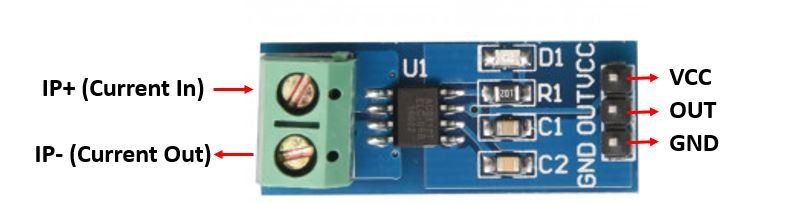
The ACS712 current sensor module has three pins namely GND, OUT and VCC. The table below gives a brief description of them.
| Pin | Description |
|---|---|
| VCC | Positive power supply (5V) pin that powers up the sensor module. |
| GND | This is the ground pin. |
| OUT | This is the output pin that gives analog voltage proportional to the current. |
Apart from these three pins, the ACS712 module features a two pole connector. Insert the wire of the device whose current you need to measure. Connect the load with IP+ terminal and connect the power supply’s negative with IP-.
Interfacing ACS712 Current Sensor Module with Arduino
In this section, we will discuss how to connect the ACS712 current sensor module with Arduino. It is very simple and easy to do because of the least number of pins involved. For demonstration purposes, we will include a 16×2 LCD in our project to display the voltage and AC current readings.
We will require the following components for this project.
Required Components:
- Arduino UNO
- ACS712 Sensor Module
- 16×2 LCD
- Load with power source
- Connecting Wires
- Breadboard
Assemble the devices as shown in the schematic diagram below:
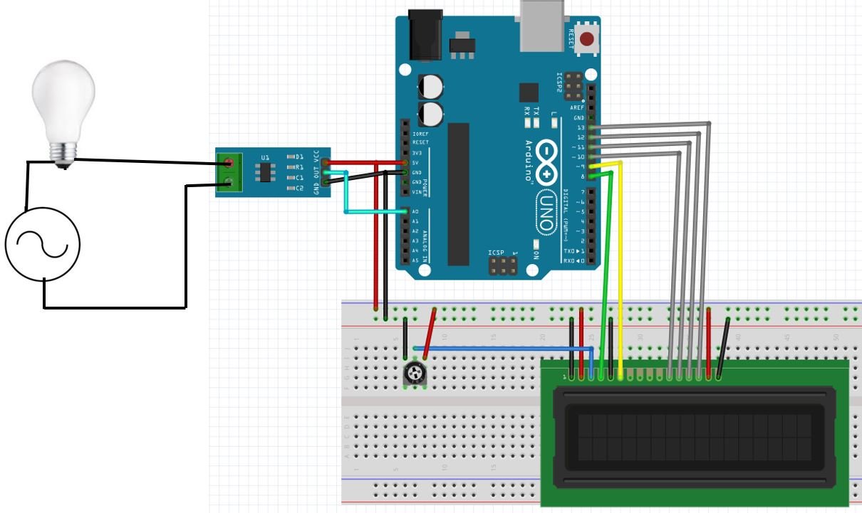
Connect the sensor module’s VCC pin with 5V terminal of Arduino UNO. This will power up the sensor. Connect the OUT pin with an analog pin of Arduino. We are suing A0 of Arduino UNO to connect with the OUT pin. Moreover connect the GND pin with the common ground of Arduino and LCD. Using the two pole connector, connect the wire of the load with these terminals. Connect the load with IP+ terminal and connect the power supply’s negative with IP-. Connect the ACS712 module in series with the load.
Arduino connections with 16×2 LCD
We are using the following connections as described below. Refer to the schematic diagram to have a clearer idea of the connections.
| 16×2 LCD | Arduino |
|---|---|
| D4 – D7 | Pin 10,11,12,13 |
| Enable | Pin 9 |
| RS | Pin 8 |
| RW | GND |
| VEE | 10k POT (Middle Leg) |
| VSS | GND |
| VCC | +5V |
| LED+ | +5V |
| LED- | GND |
Arduino Sketch for AC current measurement using ACS712 Module
Open your Arduino IDE and go to File > New. Copy the code below in that file.
This sketch reads the output ADC value of the ACS712 sensor 500 times and averages it. This averaged reading is then used to obtain the voltage and consequently the current flowing through the fire.
#include <LiquidCrystal.h> //library for LCD

LiquidCrystal lcd(8, 9, 10, 11, 12, 13);

int OUT = A0;

const int Num_readings = 500;
long int sensor_value = 0;

float voltage = 0;
float current = 0;

void setup() {
  Serial.begin(9600);
  lcd.begin(16, 2);
 // Print a message to the LCD.
 lcd.setCursor(0,1);//Setting cursor on LCD
 lcd.print("MICROCONTROLLERS");//Prints on the LCD
 delay(3000);//time delay for 3 sec
 lcd.clear();//clearing the LCD display
 lcd.display();//Turning on the display again
 lcd.setCursor(1,0);//setting LCD cursor
 lcd.print("Reading Values from");//prints on LCD
 lcd.setCursor(1,1);
 lcd.print("ACS712");
 delay(2000);//delay for 2 sec
}

void loop() {

  for (int i = 0; i < Num_readings; i++)
  {
    sensor_value += analogRead(OUT);
    delay(2);
  }

  sensor_value = sensor_value / Num_readings;
  voltage = sensor_value * 5.0 / 1024.0;
  current = (voltage - 2.5) / 0.185;

  Serial.print("ADC Value: ");
  Serial.print(sensor_value);

  Serial.print("   ADC Voltage: ");
  Serial.print(voltage);
  Serial.print("V");
  lcd.setCursor(0, 0);
  lcd.print("Voltage:");
  lcd.setCursor(9, 0);
  lcd.print(voltage);

  Serial.print("   Current: ");
  Serial.print(current);
  Serial.println("A");
  lcd.setCursor(1, 1);
  lcd.print("Current:");
  lcd.setCursor(9, 1);
  lcd.print(current);
}
How the Code Works?
We will start by including the library required for our 16×2 LCD as shown below:
#include<LiquidCrystal.h>Next, we declare the Arduino pins that are connected with the LCD. To define connections, we use the following line of code. This line creates a LiquidCrystal object and lcd is a name of the object that we are going to use to call LCD functions. You can also use any other name.
LiquidCrystal lcd(rs, en, d4, d5, d6, d7)In our case, the pins are 8, 9, 10, 11, 12, and 13 respectively.
LiquidCrystal lcd(8, 9, 10, 11, 12, 13);Declare an int variable called ‘OUT’ to store the Arduino analog pin connected with the ACS712 sensor module’s OUT pin. It is pin A0 in our case.
int OUT = A0; setup()
Open the serial communication at a baud rate of 9600.
Serial.begin(9600);Next, we use lcd.begin() routine to define the size of an LCD. The first argument to this function is a number of rows and the second argument is a number of columns. For instance, this line declares the size as 16 columns and 2 rows. That means 16×2 size.
lcd.begin(16, 2);Print a series of initiatory messages on the LCD display with delays in between.
 lcd.setCursor(0,1);//Setting cursor on LCD
 lcd.print("MICROCONTROLLERS");//Prints on the LCD
 delay(3000);//time delay for 3 sec
 lcd.clear();//clearing the LCD display
 lcd.display();//Turning on the display again
 lcd.setCursor(1,0);//setting LCD cursor
 lcd.print("Reading Values from");//prints on LCD
 lcd.setCursor(1,1);
 lcd.print("ACS712");
 delay(2000);//delay for 2 sec
loop()
Inside the loop() function, we will read the analog output from the OUT pin using analogRead() function. This value is saved in the float variable ‘sensor_value.’ We will take 500 readings and then calculate the average value and save the value in ‘sensor_value.’
for (int i = 0; i < Num_readings; i++)
  {
    sensor_value += analogRead(OUT);
    delay(2);
  }

  sensor_value = sensor_value / Num_readings;
To find the voltage reading we will use the following formula:
voltage = sensor_value * 5.0 / 1024.0;Likewise, we calculate the current reading using the following formula:
current = (voltage - 2.5) / 0.185;Now print the ADC, voltage and current readings in the serial monitor.
  Serial.print("ADC Value: ");
  Serial.print(sensor_value);

  Serial.print("   ADC Voltage: ");
  Serial.print(voltage);
  Serial.print("V");

  Serial.print("   Current: ");
  Serial.print(current);
  Serial.println("A");
The voltage and current readings will also be displayed on the 16×2 LCD using the following lines of code.
  lcd.setCursor(0, 0);
  lcd.print("Voltage:");
  lcd.setCursor(9, 0);
  lcd.print(voltage);

  lcd.setCursor(1, 1);
  lcd.print("Current:");
  lcd.setCursor(9, 1);
  lcd.print(current);
Demonstration
Make sure you choose the correct board and COM port before uploading your code to the board. Go to Tools > Board and select Arduino UNO. Next, go to Tools > Port and select the appropriate port through which your board is connected.

Click on the upload button to upload the code to the board.
After you have uploaded your code to the development board, open the serial monitor and set the baud rate to 9600. You will be able to view the voltage readings (V) and AC current (A) flowing through the wire on the LCD.
How come the value of my circuit keep increasing?
How can we measure the ac Voltage using ACS712 sensor?
Hello,
Great Explanation & Job Done.
But what is that 5000 in the line
” Voltage = (adcvalue / 1024.0) * 5000; // Gets you mV ”
Thanks in Advance,
Ravi
hi
can me tell me the code and simulation for converting analog speed of stepper motor into digital frequency pulses using ardunio
nandhini
i have a problem in simulating proteus .as i write a code for voltage measurement and sketch the desired circuitry in proteus but the A0 pin doesn’t read the value .Kindly if u have any idea ,i will be very thankful
I think there is a bug in the libraries which you have downloaded from the website delete those library files and again re download them so that you can get the output
while running this coding in proteus im getting this error message.. how can i solve this ??
“Invalid opcode 0x9419 at PC=0x1890 “
does this coding valid for dc current ?
Sir, is this circuit measures the current in zero when we turn off ac power supply?
If no
Then. Why?
If yes
Then How.
where is the code?
i have simulated this program. but value in screen does not match with original value & also if i change the input current no change in display
You need to make sure, you have used a correct connection with ADC channel of Arduino
Sir..I want to show 220v and 50mhz.Whats the formula..?thank’s.
This is buggy code. It ignores Nyquist Sampling theorem. Simply measuring 500 times without any knowledge of what is measured gives an result you cannot trust. The 500 count loop is executed in few ms. The period of AC (50Hz) is 20 ms. So you’re sampling your AC for a fraction of the period of the AC. The maxvalue in those 500 points can be any value. And if just ‘any’ value is measured, nothing is measured. You need an algoritm to measure te RMS-value. You need to measure for more than 20 ms at a sample rate higher than 100 Hz. Above that it is advised to use the same reference voltage for the ADC in the AVR and the ACS.
For your kind information, we are getting each sample every 104 µs which is a default sampling time of the analogRead() function of Arduino. By taking 500 samples we make sure that we do not miss a peak value and check it for 2-3 AC cycles. For your second concern, 500*0.104ms = 50ms which not a fraction of the AC period. You should have done the homework first before commenting on this post.
Hi, I have tried to simulate the circuit using the above code. However, the reading on the AC AmMeter and the value display on the LCD do not match each other. Check back both the circuit and the code but nothing seems to be out of order. Is there any recommendation?
Thank you very much.
This is the code I have been implementing. Of course, I tried to apply your method into my simulation using Proteus 8.8 but I seem to not the desired results..
// include the library code:
#include //library for LCD
// initialize the library with the numbers of the interface pins
LiquidCrystal lcd(8, 9, 10, 11, 12, 13);
//Measuring Current Using ACS712
const int analogchannel = A0; //Connect current sensor with A0 of Arduino
int sensitivity = 185; // use 100 for 20A Module and 66 for 30A Module
float adcvalue = 0;
int offsetvoltage = 2500;
double Voltage = 0; //voltage measuring
double ecurrent = 0; //current measuring
double power = 0; //power measuring
void setup() {
//baud rate
Serial.begin(9600);//baud rate at which arduino communicates with Laptop/PC
// set up the LCD’s number of columns and rows:
lcd.begin(20, 4); //LCD order
}
void loop() //method to run the source code repeatedly
{
unsigned int temp = 0;
float maxpoint = 0;
int i = 0;
for(i = 0; i maxpoint)
{
maxpoint = temp;
}
}
adcvalue = maxpoint;
Voltage = (adcvalue / 1024.0) * 5000; // Gets you mV
ecurrent = ((Voltage – offsetvoltage) / sensitivity);
ecurrent = ( ecurrent ) / ( sqrt(2) );
power = (ecurrent*220/1.13);
//Prints on the serial port
Serial.print(“Raw Value = ” ); // prints on the serial monitor
Serial.print(adcvalue); // prints the results on the serial monitor
lcd.clear(); // clears the display of LCD
delay(1000); // delay of 1 sec
lcd.display();
lcd.setCursor(1,0);
lcd.print(“ADC Value = “);
lcd.setCursor(13,0);
lcd.print(adcvalue);
Serial.print(“\t mV = “); // shows the voltage measured
Serial.print(Voltage,3); // the ‘3’ after voltage allows you to display 3 digits after decimal point
lcd.setCursor(1,1);
lcd.print(“Voltage = “);
lcd.setCursor(11,1);
lcd.print(Voltage,3);
lcd.setCursor(18,1);
lcd.print(“mV”); //Unit for the voltages to be measured
Serial.print(“\t ecurrent = “); // shows the current measured
Serial.println(ecurrent,3); // the ‘3’ after current allows you to display 3 digits after decimal point
lcd.setCursor(1,2);
lcd.print(“Current = “);
lcd.setCursor(11,2);
lcd.print(ecurrent,3);
lcd.setCursor(16,2);
lcd.print(“A”); //unit for the current to be measured
Serial.print(“\t power = “); // shows the power measured
Serial.println(power,3); // the ‘3’ after power allows you to display 3 digits after decimal point
lcd.setCursor(1,3);
lcd.print(“Power = “);
lcd.setCursor(10,3);
lcd.print(power,3);
lcd.setCursor(18,3);
lcd.print(“W”); //unit for the power to be measured
delay(2500); //delay of 2.5 sec
}
If you’re having problems with stability I find it much more accurate to use the mean adc value as the adc offset, rather than a fixed value. The mean current is zero so the mean adc value corresponds to zero current. This is effectively auto-calibrating the sensor on each reading and whilst the sensor itself is not heat-dependent the resistors you use for your potential divider most certainly are.
What all the values for Input voltage?
My adcvalues is reaching upto 1023, can anybody tell me how to change it?
My ammeter current value and lcd current value are not matching
what values vsin received?