In this tutorial, we are going to look at DC motor Speed Control through LabVIEW and Arduino. In today’s tutorial, we will see how we can control the speed of a DC motor through LabView and Arduino. We will start building VI from scratch and then control the speed and direction of the DC motor from the LabVIEW graphical user interface. If you do not know about LabVIEW, I suggest you check out this post on Getting Started with LabVIEW and Arduino with LabVIEW.
Hardware Components – DC Motor Speed Control with LabVIEW
Hardware requirements for this project are as follows:
- Arduino UNO board
- 5V DC motor
- L293D motor driver
- Breadboard
- Jumper wires
Note: Make sure to use a 5V DC motor as it can get directly powered from the Arduino; otherwise, you might have to modify the motor driving circuit for high current and voltage to drive the motor. Another thing to make sure of is that if you are using an Arduino motor driver shield (with integrated chips) instead of the L293D motor driver, a little modification of the code is required for the LabVIEW program to run with the L293D motor driver shield.

Software Requirements:
In this section, we will list the software used in this tutorial.
- LabVIEW
- Arduino interfacing for LabVIEW
Note: If you have not installed the software mentioned above, please refer to our previous article where we programmed Arduino with LabVIEW. In the previous tutorial, we wrote our first program to control the LED connected to pin 13 of the Arduino UNO board with a push button created in LabView.
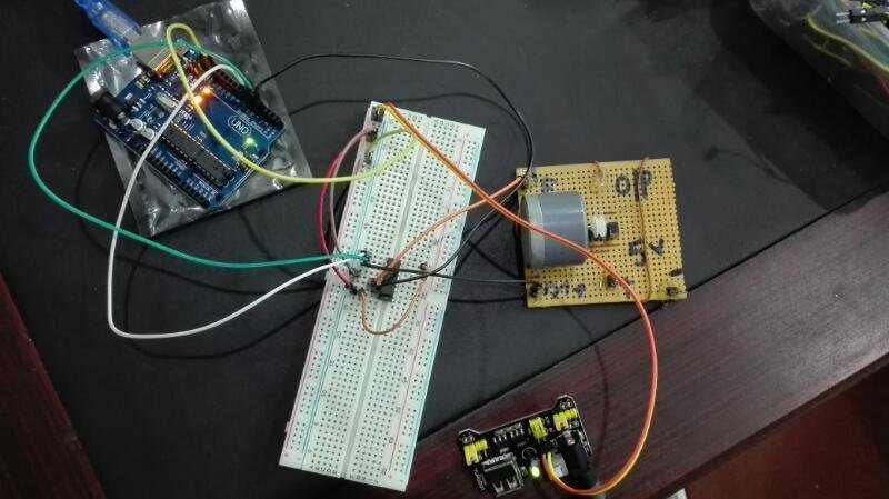
Schematic Diagram
In this section, we will show a step-by-step process to wire the circuit correctly. Below is the pin configuration of motor driver L293D.

Put the motor driver L293D chip in the middle of the breadboard. This ensures that pins on both sides are not shorted together.
Follow the table below to connect the L293D motor driver with the Arduino Board:
| Motor Driver L293D pins | Arduino UNO board pins |
|---|---|
| 8 and 16 | 5V or VIN |
| 4 and 5 | GND |
| 7 | 4 |
| 2 | 5 |
| 1 | 6 |
Now we will move on to connecting the motor with the L293D driver chip. The connections are as follows:
| Motor Driver L293D pins | 5V DC motor pins |
|---|---|
| 3 | Terminal 1 |
| 6 | Terminal 2 |
We are done with the hardware connections of the circuit for this project; now we can move on to the next step, which is the programming part in LabVIEW.
LabVIEW Program for Controlling DC Motor Speed and Direction
In this section, we will write a LabVIEW Program to control the speed and direction of a DC motor.
Initializing the LabVIEW Program
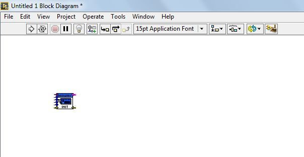
- Start the LabVIEW software.
- Create a Blank VI as shown in Tutorial 1.
- Go to the LabVIEW “Block Diagram” Panel.
Using Arduino Components in Labview
- Right-click on the white space. Go to “Arduino” and select “init”. This will add Initializations to the Arduino board.

- Bring Cursor anywhere in the LabVIEW “Block Diagram” panel and place the “Init”.
Setting Void Setup Function in LabVIEW
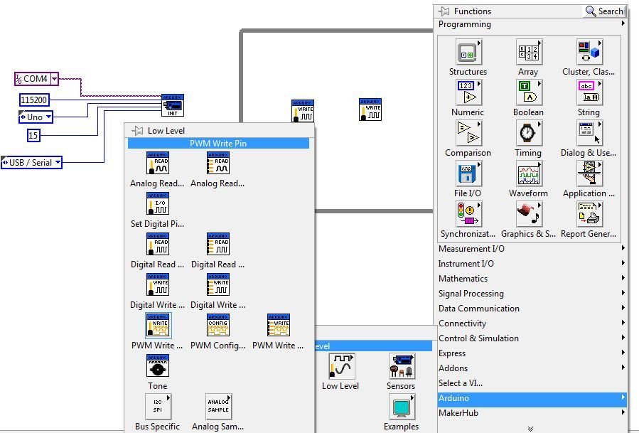
- The first input is “VISA resource”. It is the serial port we are using for interfacing with Adruino. We can find it in the “device manager” of our computer under “ports (COM & LPT)…”. Make sure the Arduino board is connected to the computer; otherwise, it won’t be shown. In our case, it is COM4.
- Bring the cursor to the first input of “Init” until it shows “VISA resource”. Right-click on it. Go to “create” and select “constant”. As it will be a constant value of port, which will always be used for serial communication.

- Click on the arrow; it will show the available options. In our case, it’s “COM4”. Select the appropriate one after checking the device manager as mentioned above; otherwise, it won’t work.

- The second input is “Baud Rate”. Create it as a constant, as done for “VISA resource”. Right-click on “Baud Rate” then “create” and then “constant”.

- The third input is “Board Type”, the fourth is “Bytes per packet”, and the fifth is “Connection Type”. We will make them all constant.

Setting Void Loop function in LabVIEW
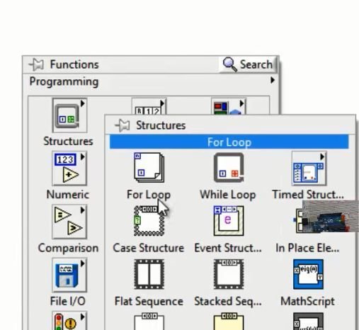
- Click on the white space on LabVIEW’s “Block Diagram” and follow “Structure → select While loop”.
- Draw a rectangle on LabVIEW’s “Block Diagram” and click on the red-colored round icon “loop condition”. Create a constant by right-clicking on it. It will show a “STOP” icon on the diagram.

Using Digital and PWM Write Functions in LabVIEW
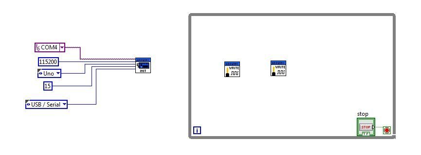
- Place 2 “Digital Write Pin” and 1 “PWM Write Pin” blocks as shown below. We need two digital write pins to control the direction of the motor in two different directions (left and right). A PWM pin will be used to control the speed of the motor.
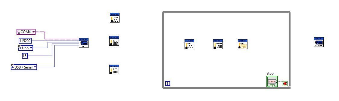
Similarly, place the second “Digital Write”. Place the “PWM write pin” Block on the LabVIEW “Block Diagram” panel.
- Place “Close Block” as follows:

- This process results in the following LabVIEW Block diagram:

- Click on the white space on “Block Diagram” and follow “Arduino → Low Level → and select “Set Digital Pin”.

- Place “Set Digital Pin” on “Block Diagram”. Place 3 “Set Digital Pin” blocks on the “Block Diagram”. These results are as follows:
Making Connections in the LabVIEW Program
- Join the above diagram as shown below. You can take help from previous tutorials.

- Further, join the blocks as shown in the diagram. We also need to place two more “close” blocks. For PWM input, we create control as done previously, and for all other inputs, we create constants.

Opening LabVIEW program in Arduino IDE
- Now start the Arduino IDE.
- Click “File”, then “Open”, as shown below. Now, go through all these folders from “Computer” onward and open the LIFA_BASE Arduino file.

- Upload the program opened in Arduino IDE using the Arrow button on top of Arduino IDE.
- Once uploading is done, close the Arduino IDE. It’s very important to close the Arduino IDE because both LabVIEW and Arduino are using COM4. If not closed, LabVIEW will not be able to communicate, and LabVIEW software will crash.
- Now go to the front panel in LabVIEW and run the program in the toolbar menu of LabVIEW.
- When we right 1 at the place of “direction 1”, the motor rotates in one direction. When we right 1 at the place of “direction 2”, the motor rotates in the other direction. Be careful when doing this; do not set 1 for “direction 1” and “direction 2” simultaneously. Both direction controls should not be on at once. If one direction control is 1, the other should be 0. Otherwise, L293D will suffer permanent damage. One more thing to note is that speed should be somewhere between 0 and 255; otherwise, the motor will not rotate.
- By varying speed between 0 and 255, we can see that motor speed varies. At 0, the motor stops, and at 255, it rotates at maximum speed.
Video Demo:
In summary:
In this tutorial, we learned DC motor control with LabVIEW and Arduino and how to interface LabVIEW with Arduino to precisely regulate DC motor speed and direction.
You may also like to read:
- Control DC Motor using L298N Driver with Raspberry Pi Pico and MicroPython
- DC Motor Speed and Direction Control with L293D Driver IC and Arduino
- Interface L298N DC Motor Driver Module with ESP32
- ESP32 Web Server Control DC Motor Speed using L298N Driver
- ESP32 Web Server Control DC Motor Speed using L298N Driver
- DC motor Speed control using pic microcontroller
- Control 2 DC Motors via Bluetooth and Arduino
Thanks a lot Bilal
Please can you upload Ardunio IDE code here?
Urgently needed.
very good thanks
if there are encoder speed sensor how program it with labview and arduino to draw and calculate speed in rpm .please help me .
Sir i am using 12v dc motor with l293n driver, i performed every thing fine as u discussed, even downloaded lifa_base but still my motor is not moving.
I joined enable port of l293n to arduino port 6,int1 and2 with 5 and 4. Uploaded the code lifa. But not working help me.
please could you provide the arduino code