Earthquake Detector using Arduino and MPU6050 sensor: Earthquake detector is a device that detects earthquake shocks. According to research, approximately 800,000 earthquakes occurs in a year which kills so many lives and destroys buildings. Our project is a small effort to overcome the loss which occurs due to the earthquake. This detector can detect the minor shocks and alarm you to evacuate to a safe place. The most important component of this detector is MPU 6050 module which we will talk later. Arduino is the brain of this detector, LCD is used to display message and Led and buzzer is used as indicators.
Block Diagram Earthquake Detector using Arduino 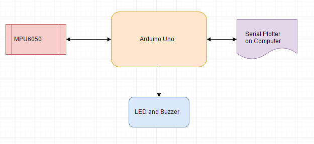
Components Required
- ArduinoUno: We used Arduino Uno because is cheap and it fits perfect for this project as we need two analog pins and eight digital pins. It is easy to program and have a penalty of memory to store program.
- MPU6050: MPU6050 is 6 Axis Accelerometer and gyroscope. It is generally a motion tracking device. It is also capable of measuring temperature. It consumes less power and very cheap in price.
Here are some feature MPU6050
- Gyroscope operating current: 3.6mA.
- Accelerometer normal operating current: 500µA.
- Standby current: 5µA.
- Operating voltages lies between 2.37v to 3.46v
- Improved low-frequency noise performance.
- Digital-output temperature sensor.
Pin description of MPU6050 module:

- Vcc: Supply voltages of 3.3 to this pin.
- GND: This pin connected to ground.
- SCL: I2C Serial Clock Pin.
- SDA: I2C Serial Data Pin.
- XDA: I2C Master Data pin for an external sensor.
- XCL: I2C Master Clock pin for an external sensor.
- AD0: I2C Slave Address LSB.
- INT: Interrupt digital output pin.
- 16×2 LCD: LCD is used to show alphanumeric characters. It has total 16 pins. A 10K ohm potentiometer is connected with pin three to set the contrast of the LCD. It also contains a backlight LED. In this project LCD, we use is 16×2 which means we can display 16 characters in two lines. In this project, LCD is used to show whether the shocks are detected or not.
- Led: A red led is used to indicate that earthquake shocks are detected and the red color is also representing danger.
- Buzzer: A buzzer generates a high sound which alarms the people that earthquake shocks are detected.
- Resistor and some jumper wires
Circuit Diagram of Earthquake Detector using Arduino 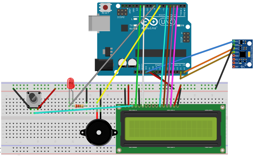
Working of Earthquake Detector using Arduino block diagram
The Arduino first of all initialize MPU 6050. Check the sleep mode and a clock signal from module then started reading the values. There are maximum and minimum values are declared in the code it checks if the value is greater or smaller than the desired values then it starts the buzzer, led and display message “***Earthquake***”o n the LCD. If the values are normal then it does nothing.
Implementation of Earthquake Detector using Arduino

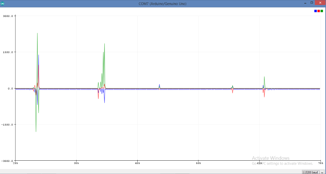
Serial Plotter for Earthquake Detector using Arduino
Code of Earthquake Detector using Arduino
#include <LiquidCrystal.h>

#include <Wire.h>

#include <MPU6050.h>

#define minval -5

#define maxval 3

MPU6050 mpu;

LiquidCrystal lcd(12, 11, 5, 4, 3, 2);

void setup()

{   lcd.begin(16, 2);

    Serial.begin(115200);

    pinMode(7,OUTPUT);

    pinMode(8,OUTPUT);

    lcd.print("   EarthQuake ");

    lcd.setCursor(0, 1);

    lcd.print("   Detector");

    delay (2000);

    lcd.clear();

  // Initialize MPU6050

  Serial.println("Initialize MPU6050");

  while(!mpu.begin(MPU6050_SCALE_2000DPS, MPU6050_RANGE_2G))

  { Serial.println("Could not find a valid MPU6050 sensor, check wiring!");

    delay(500);}

  mpu.setThreshold(3);

  // Check settings

  checkSettings();

}


void checkSettings()

{

  Serial.println();


  Serial.print(" * Sleep Mode:        ");

  Serial.println(mpu.getSleepEnabled() ? "Enabled" : "Disabled");

  Serial.print(" * Clock Source:      ");

  switch(mpu.getClockSource())

  {case MPU6050_CLOCK_KEEP_RESET:     Serial.println("Stops the clock and keeps the timing generator in reset"); break;

    case MPU6050_CLOCK_EXTERNAL_19MHZ: Serial.println("PLL with external 19.2MHz reference"); break;

    case MPU6050_CLOCK_EXTERNAL_32KHZ: Serial.println("PLL with external 32.768kHz reference"); break;

    case MPU6050_CLOCK_PLL_ZGYRO:      Serial.println("PLL with Z axis gyroscope reference"); break;

    case MPU6050_CLOCK_PLL_YGYRO:      Serial.println("PLL with Y axis gyroscope reference"); break;

    case MPU6050_CLOCK_PLL_XGYRO:      Serial.println("PLL with X axis gyroscope reference"); break;

    case MPU6050_CLOCK_INTERNAL_8MHZ:  Serial.println("Internal 8MHz oscillator"); break;

  }

  Serial.print(" * Gyroscope:         ");

  switch(mpu.getScale())

  {case MPU6050_SCALE_2000DPS:        Serial.println("2000 dps"); break;

    case MPU6050_SCALE_1000DPS:        Serial.println("1000 dps"); break;

    case MPU6050_SCALE_500DPS:         Serial.println("500 dps"); break;

    case MPU6050_SCALE_250DPS:         Serial.println("250 dps"); break:}

  Serial.print(" * Gyroscope offsets: ");

  Serial.print(mpu.getGyroOffsetX());

  Serial.print(" / ");

  Serial.print(mpu.getGyroOffsetY());

  Serial.print(" / ");

  Serial.println(mpu.getGyroOffsetZ());

  Serial.println();}

void loop()

{   Vector rawGyro = mpu.readRawGyro();

  Vector normGyro = mpu.readNormalizeGyro();

  Serial.print(" Xraw = ");

  Serial.print(rawGyro.XAxis);

  Serial.print(" Yraw = ");

  Serial.print(rawGyro.YAxis);

  Serial.print(" Zraw = ");

  Serial.println(rawGyro.ZAxis);

if(normGyro.XAxis > maxval || normGyro.XAxis < minval && normGyro.YAxis > maxval || normGyro.YAxis  < minval && normGyro.ZAxis > maxval || normGyro.ZAxis  < minval)

{ digitalWrite(7,HIGH);

  digitalWrite(8,HIGH);

  delay(300);

  digitalWrite(7,HIGH);

  digitalWrite(8,HIGH);

  delay(300);

  lcd.clear();

  lcd.print("***EarthQuake***");

  delay (1000);

  lcd.clear();}

 else{digitalWrite(7,LOW);

 digitalWrite(8,LOW);}

  Serial.print(" Xnorm = ");

  Serial.print(normGyro.XAxis);

  Serial.print(" Ynorm = ");

  Serial.print(normGyro.YAxis);

  Serial.print(" Znorm = ");

  Serial.println(normGyro.ZAxis);

  delay(10);}
Hi Bilal,
Just saying hi to a like mind.
Where are you?
We, Fay and I, are in the Pacific North West.
I am relearning programming in C after a lifetime doing eng/physics.
Hmmm………
jt
Hi Bilal,
Can you share with me, where to find the correct MPU6050 library sams as you use
#include this library is missing in ur repositiry
could someone tell me what the object to the left of the led is plz
Jordan, it is a potentiometer. Take a look at the 16×2 LCD link near the top of this article. It shows more information. That link indicates it is a 10k pot. I hope that helps!
With this source code i have error that ” normGyro was not declered in this scope”. Which way do i solve this?Please!
can you make the circuit diagram of this circuit using proteus software? will there be any mpu6050 library?
pls, send the mpu6050 library for arduino used in the above code
my mail : chakradharkintada@gmail.com
Good morning sir.
Can you help me do this detector.
I am currently a school Disaster risk reduction coordinator and im doing a thing like this. Hehe.
hello everyone..
i tried everything .. 12cdev, ide 1.6.9, ide 1.0.1, ide 1.8.8.. just one message show ..error.. ‘class MPU6050’ has no member named ‘begin, initialize is not alternative begin also. i use Arduino uno china .
please give me full process for uploading this software. if u can make a video (full process for uploading this software) mpu6050 it will be viral…
Thanks..
my email id is: realrobin0007@gmail.com
pls, send the mpu6050 library for arduino used in the above code
my mail id: siddhant.tagade16@gmail.com
can you send me mpu6050 library if u have pls
mail to: shankarg6251@gmail.com
can you send me mpu6050 library if u have
can you send me mpu6050 library
You can download library from here:
https://github.com/jrowberg/i2cdevlib/tree/master/Arduino/MPU6050
hello guys
i tried everything .. 12cdev, ide 1.6.9, ide 1.0.1, ide 1.8.8.. just one message show ..error.. ‘class MPU6050’ has no member named ‘begin, initialize is not alternative begin also. i use Arduino uno
please give me full process for uploading this software. i
Thanks..
my email id is: allawanjustinreino@gmail.com
https://github.com/jarzebski/Arduino-MPU6050 library 😀
Arduino: 1.6.10 (Windows 10), Board: “Arduino/Genuino Uno”
Sketch uses 10,434 bytes (32%) of program storage space. Maximum is 32,256 bytes.
Global variables use 1,132 bytes (55%) of dynamic memory, leaving 916 bytes for local variables. Maximum is 2,048 bytes.
C:\Program Files (x86)\Arduino\hardware\tools\avr/bin/avrdude -CC:\Program Files (x86)\Arduino\hardware\tools\avr/etc/avrdude.conf -v -patmega328p -carduino -PCOM18 -b115200 -D -Uflash:w:C:\Users\Admin\AppData\Local\Temp\build9c6bd092ad75e7d76aeb4d8d2b28fb75.tmp/sketch.ino.hex:i
avrdude: Version 6.3, compiled on Jun 22 2016 at 16:05:21
Copyright (c) 2000-2005 Brian Dean, http://www.bdmicro.com/
Copyright (c) 2007-2014 Joerg Wunsch
System wide configuration file is “C:\Program Files (x86)\Arduino\hardware\tools\avr/etc/avrdude.conf”
Using Port : COM18
Using Programmer : arduino
Overriding Baud Rate : 115200
avrdude: stk500_recv(): programmer is not responding
avrdude: stk500_getsync() attempt 1 of 10: not in sync: resp=0xbb
avrdude: stk500_recv(): programmer is not responding
avrdude: stk500_getsync() attempt 2 of 10: not in sync: resp=0xbb
avrdude: stk500_recv(): programmer is not responding
avrdude: stk500_getsync() attempt 3 of 10: not in sync: resp=0xbb
avrdude: stk500_recv(): programmer is not responding
avrdude: stk500_getsync() attempt 4 of 10: not in sync: resp=0xbb
avrdude: stk500_recv(): programmer is not responding
avrdude: stk500_getsync() attempt 5 of 10: not in sync: resp=0xbb
avrdude: stk500_recv(): programmer is not responding
avrdude: stk500_getsync() attempt 6 of 10: not in sync: resp=0xbb
avrdude: stk500_recv(): programmer is not responding
avrdude: stk500_getsync() attempt 7 of 10: not in sync: resp=0xbb
avrdude: stk500_recv(): programmer is not responding
avrdude: stk500_getsync() attempt 8 of 10: not in sync: resp=0xbb
avrdude: stk500_recv(): programmer is not responding
avrdude: stk500_getsync() attempt 9 of 10: not in sync: resp=0xbb
avrdude: stk500_recv(): programmer is not responding
avrdude: stk500_getsync() attempt 10 of 10: not in sync: resp=0xbb
avrdude done. Thank you.
Problem uploading to board. See http://www.arduino.cc/en/Guide/Troubleshooting#upload for suggestions.
This report would have more information with
“Show verbose output during compilation”
option enabled in File -> Preferences.
Im getting this error while uploading.. wt to do???
I followed the Wiring Diagram and tried to troubleshoot, and then I found zero mistakes on the hardware. I uploaded the code from arduino 1.8.13 and it was also done uploading. Can someone help me? I use the same Arduino Uno board, MPU6050, and LCD as this schematic
Hello guys, so I tried to make this detector, but it turns out it didn’t work. I did troubleshooting for the hardware, and nothing was wrong. The program also uploaded well from Arduino 1.8.13 Version. I use the same Arduino Uno, MPU6050, and LCD. Can someone give me an idea of what is being wrong? Thanks in advance
Are you getting any output on serial monitor of Arduino?