In this article we are going to uncover details about Arduino Due. As we all know that Arduino boards are quite inexpensive and are simple in use for beginners too. These boards are useful in making simple as well as complex projects. Many preloaded Arduino programs are available and a person with little knowledge of programming can also use these boards to give reality to his idea
INTRODUCTION TO ARDUINO DUE
The first Arduino board which is based on 32 – bit ARM core microcontroller is Arduino Due. It is a microcontroller having Atmel SAM3X8E Arm Cortex – M3 CPU. Arduino.cc developed this microcontroller. As other development boards of Arduino, we can also plug this device in computer via USB cable and start working on it. Other boards of Arduino are ATMEGA based boards. Arduino DUE is almost similar to other ATMEGA based board except few differences which are listed below.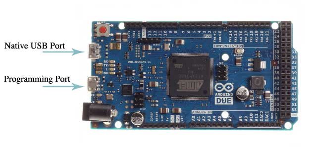
- Operating voltage
- Serial ports on Arduino DUE
- Automatic software resetting by using native or programming port
- USB host
- ADC and PWM resolutions
- Expanded SPI functionality
These differences will be discussed shortly in key features of this article so keep going with us. We are going to discuss the pin configuration, key features, specifications, difference from other board, programming, shield compatibility and projects that are being developed using this board

PIN CONFIGURATIONS AND USES of Arduino Due
- VIN: To give input voltage to board by using external power supply
- 5 V: To give regulated supply of 5 V from regulator on board. Generally this supply is not preferred as this bypasses the on-board regulator and can damage our board in case of high voltage.
- 3.3 V: It is generated by on-board regulator and maximum current that can be drawn from this pin is around 800 mA. This regulator is also used in supplying power to microcontroller attached to it
- GND: These pins are used to provide ground to our circuit
- IOREF: To provide reference voltage on which microcontroller operated
- Digital Input / Output pins: Total 54 digital pins are on board and these pins operate only at 3.3 V. Range of current that each pin can draw is from 3 mA to 15 mA and can receive a current in range of 6 mA to 9 mA.
- TX: Used for transmitting TTL serial data
- RX: Used for receiving TTL series data
- PWM: to provide 8 – bit pulse width modulation and its resolution can be changed with the help of analogWriteResolution () function.
- SPI: To support SPI communication
- Analog pins: 12 pins can serve as analog inputs and each provide 12 bits of resolution
- AREF: Used as reference voltages for analog inputs
- Reset: To reset microcontroller
- Erase: to erase the stored information on board
- DAC1 and DAC2: These pins are used to provide true analog output along with 12 – bits of resolution by making use of analogWrite () function. Output range for these pins is from 0.55 volts – 2.75 volts.
- TWI 1 and TWI 2: To support TWI communication
- CAN: CANRX AND CANTX : to support CAN communication
- UART: It is helpful for serial communication setup. There are 4 pins for this purpose i.e. we can communicate with multiple devices at a time by setting up serial communication with them using these pins.
- JTAG header: Common interface of hardware that help us to directly communicate with external chips of our board. 4 pins are used for this purpose labeled as TCK , TD0 ,TMS and TDI
SPECIFICATIONS of Arduino Due IN TERMS OF VOLTAGE AND CURRENT
- Operating voltage : 3.3 V
- Input voltage recommended : 7 – 12 V
- Input voltage limit : 6 – 16 V
- DC current on all input / output pins : 130 mA
- DC current in 3.3 V pin : 800 mA
- DC current in 5 V pin : 800 mA
SPECIFICATIONS of Arduino DueIN TERMS OF MEMORY
- Flash memory: 512 KB
- SRAM: 96 KB ( in two blocks of 64 KB and 32 KB )
AUTOMATIC SOFTWARE RESET:
Unlike other boards of Arduino, simply pressing reset button will not erase all data on our board. It will only reset SAM3X. For this purpose native and programming ports of our board are used and advantage / disadvantages of these 2 ports are given under programming heading.
USB HOST:
This board can act as a host which means that power to attached device will be provided by Arduino DUE. One thing we should keep in mind before using our Arduino DUE as USB host that DC power connector should be used otherwise we may damage our board.
ADC AND PWM RESOLUTIONS:
An interesting feature of Arduino DUE is its ability to change its analog write and read resolutions. Read resolution is of 10 – bits and write resolution is of 8 – bits. However supported resolution in ADC and PWM is up to 12 bits
EXPANDED SPI FUNCTIONALITY:
This feature is useful when it comes to communicate with multiple devices speaking at different speed
PROGRAMMING of Arduino Due
Just like other boards on Arduino, this board also uses Arduino IDE for making programs known as sketches. One more interesting point here is that no external burner like boot loader is required to burn our code on board. When it comes to uploading these sketches, procedure is quite different from other Arduino boards because we have to erase flash memory before re-programming our board. Uploading on SAM3X is managed by ROM and it runs only when all data is erased and flash memory is empty. We can make use of any USB port from native or programming port for sketch uploading. Selection of USB port for uploading code is selected on the bases of data erasing technique used by these ports. Programming port uses hard erasing of data while native programming port uses soft erasing of data. Usually programming port is preferred i.e. hard erasing of data because if our MCU crashes or stop working in any case then hard erasing will still happen but soft erasing will not work in this case
SHIELD COMPATIBILITY of Arduino Due
This Arduino DUE is compatible with almost all shields designed for other boards of Arduino. Some of the most important shields are listed below:
- Ethernet Shield
- Wi-Fi Shield
- Motor Shield
PROJECTS related to Arduino Due
Arduino DUE has a large number of input and output pins just like Arduino Mega. However it can be used in a variety of projects in which high processing speed is required. Some of the projects developed by using this board are listed below
- Industrial automation
- Home automation
- VR (virtual reality) applications
- Android applications
- GSM based projects
- Embedded systems
- Speech recognition
- IoT (internet of things) notes printer
- Wireless weather stations
That’s all for this article. I hope you enjoyed reading this article. Any question and queries related to this article can be asked in comment section below.
Hi,
Thankyou for that article. I have just started a project using a cheap knock off clone from the empire of dirt but have been disappointed with the faulty code in the USB handler, ATmega16U2. Once the program has been uploaded the reset button must be pressed each time; something that can’t happen on the final version as it is part of an embedded system.
I have found a post that states that there is a workaround that requires the use of the ICSP connector but in my version this connector is missing. Is there another way to access this chip to re flash the chip with the correct program?