All microcontrollers like MSP430 microcontroller has pulse width modulation modules inside them. PWM is also know pulse width modulation. PWM is used to create digital signals in the form logical high and logical low signals. PWM is used to control voltage magnitude across load. PWM is also used to control speed of dc motor by applying variable voltage across dc motor. In embedded systems projects, it has many applications especially for power electronics control, communication and digital signal processing projects. In this tutorial, we will teach you how to generate pulse width modulation using MSP430G2553 microcontroller which is available with MSP430G2 launchpad.
So this is an eight tutorial on series of tutorial on MSP430G2 launchpad. To understand this tutorial completely first you should understand about basic pin mapping and overview of this Texas instrument development board by reading getting started tutorial on MSP430 with Energia IDE. In second tutorial, we taught you how to GPIO pins of MSP430 microcontroller. You should read these tutorials first to grasp concepts of this pulse width modulation completely. Some our already posted projects which used pulse width modulation are given below:
- SPWM generation using pic microcontroller
- PWM generation using pic microcontroller
- DC motor speed control with PWM
- DC motor speed control with Bluetooth
What is pulse width modulation?
Pulse width modulation which is also known as PWM is a special type of digital signal which remain high for some time and remain low for some. For example, if timer period of PWM signal is 20ms which is 50 hertz in frequency, if the logical high time is 10ms and logical low time of signal is 10ms. So, we will say the on time of PWM is 10ms and off time is 10ms. Two method are used to generate pulse width modulation:

- Using analog components like operational amplifier
- Digital devices like microcontrollers
You may learn about it in PWM introduction article. Important concepts of PWM are defined by time period, frequency and duty cycle. Now I will define these terms one by one.
- Timer period is a total time of PWM which is equal to on time plus off time.
Time period = on time + off timer
- Duty cycle is a most important parameter used for pulse width modulation. It defines the percentage of time the signal is high.
Duty Cycle = on time / (on time + off time)
Duty cycle = on time / time period
Figure below shows the wave forms of PWM signals with different duty cycles. If digital signal is on for total time period, duty cycle will be 100 percent.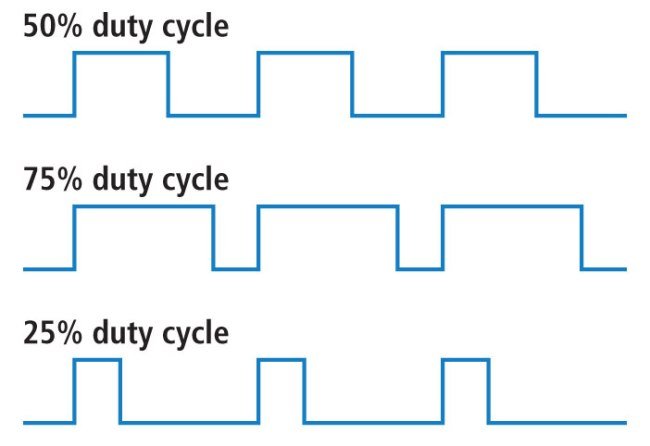
- Frequency of pulse width modulation define the rate of digital signal or in other words how quickly it completes it once cycle. Frequency and time period are inversely proportional to each other.
Circuit diagram for Pulse width modulation using MSP430 LaunchPad
So now, we’ll see how to use MSP430G2 launch pad to generate PWM. We will be using built in function of Energia IDE to generate pulse width modulation. It has a simple circuit diagram shown below:
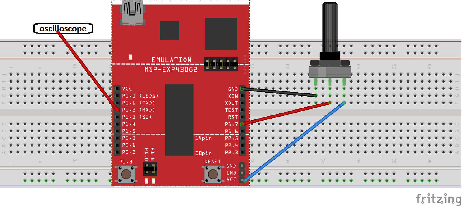
- In this circuit diagram,analog pin 7 is connected with potentiometer. Analog pin is used to measure analog voltage. you can check our seventh tutorial on how to measure analog voltage using MSP430G2 launchPad.
- We will be controlling duty cycle with the help of this potentiometer.
- If voltage across this pin will be higher, duty cycle will also be higher. I will explain more about it in programming part.
- Now the question is which of the pins of MSP430 development board can be used to generate PWM ?
- like ADC where all the pins of this board can not be user as a analog channel, not all the pins of MPS430 microcontroller can be used to generate digital signals.
- There are specific pins which can be used for this purpose. Only purple color pins can be used to generate PWM as shown in picture below:
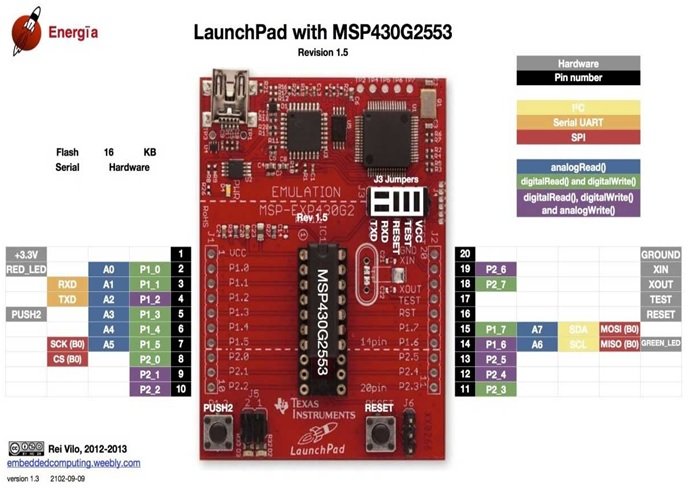
- As shown in pin mapping above pin number four, nine , ten, 12, 13, 14 and 19 can be used for this PWM generation only. So you should always consult with above pin mapping diagram while working with this development board.
- Also remember that these pins can not drive high current. If you want to feed this PWM to any other high current device like dc motor, you have to use current driver or motor driver IC between msp430 microcontroller and dc motor.
- In above circuit diagram, we have used pin number four to generate pulse width modulation.
- This pin will be connected with oscilloscope to display signal as you will see in video.
- So this is a simply circuit diagram which will be used to control duty cycle with the help of variable resistor.
- Same circuit can be used to control brightness of a light emitting diode. Instead of connecting pin number four with oscilloscope, you will connect it with LED through a resistor.
- When you will increase or decrease the duty cycle with variable resistor, you will also see its effect on the brightness of LED.
Now lets move to the coding part and see how to write code to generate digital signal. As I mentioned earlier, we are using Energia IDE in this serial of tutorials. So now lets see how to use AnalogWrite function of Energia.
PWM programming for MSP430 microcontroller
Now we will see how to write code for code for PWM programming with MSP430 microcontroller. We have seven pulse width generation pins and 8 ADC pins of MSP430G2 launchPad. Energia IDE provides analogWrite function which is used to generate digital signal with variable pulse width. So lets see how analogWrite function works?
analogWrite(pin number, duty cycle) :
- This function is built in inside the energia IDE. When you install energia IDE, this library will be installed automatically. So do not need to install it separately.
- There are two argument which you need to pass to this analogWrite function.
- First argument analogWrite function is pin number to which you want to attach PWM or from which pin you want to generate pulse width.
- you only need to mention the name of pin in first argument part like this analogWrite( 4 , duty_cycle) . It will be used to get signal from pwm pin four as shown in pin mapping above.
- Next most important argument is duty cycle. I have defined a duty cycle at the start of article.
- Duty cycle will be between 0 or 100 percent. But in MSP430 microcontroller has 8 bit PWM which means you need to specify value between 0-255. if you write value as zero, duty cycle will be zero percent and if you write 255, duty cycle will be 100% and similarly for other values in between.
- For example if you want to use pin number 4 to provide a duty cycle of 50%, you will use analogWrite function like this , analogWrite(4, 127) .
Controlling LED brightness using PWM and MSP430 microcontroller
Now we will see how to write code to display variable duty_cycle signal on oscilloscope or used to control brightness of a led. First of all in energia ide, we need to define which pin of MSP430G2 lanuchPad, we are using as PWM pin. This line is used to define pinNumber as variable. So in our program , instead of using 4 in digital write function, we will used pinNumber variable. you can also use number ‘4’ directly. We give name to pins to make code reader friendly.
int pinNumber = 4; // This pinNumber variable is used to declare pin number 4 as PWM pin
Inside this setup function, we need to declare this pin as a output pin. Because pulse width generation pin is a output pin and it is used to give signal out of microcontroller. PinMode function is used to declare pin number either as a input or output.
void setup()
{
pinMode(pinNumber,OUTPUT); // PWM pin is pwm pin. So declared it as output
}
As you already know, whatever we want to do repeatedly, we define it inside the loop function. So inside this loop function, first we have used analogRead function to measure voltage across analog channel 7. Because we will controlling brightness of LED with the help of potentiometer or variable resistor. So this line, reads the equivalent digital value of analog voltage from analog channel seven and stores its value in integer variable ADCval.
int ADCval = analogRead(A7); // read the variable resistor value
After that we are using this map function which is used to map 10 bit output of adc into 8 bit output format. As we discussed in analog to digital converter tutorial on MSP430 microcontroller, it has 8 10 bit ADC channels. So we can not pass output of ADC directly to analogWrite function, because PWM is of 8 bit. So we need to use a map function which converts 10 bit long output of ADC into 8 bit long output. So this line converts ADCval into duty_cycle where duty_cycle value will be between 0 and 255.
duty_cycle = map(ADCval, 0, 1023, 0, 255);
After that the final step is used to write this duty_cycle value and pinNumber variable to generate pulse width modulation. So this we passed these two values as a argument to this analogWrite function:
analogWrite(pinNumber, duty_cycle); // it will generate pwm according pinNumber and duty_cycle
For demonstration of this tutorial, you can check this video lecture:
Complete code For PWM using MSP430G2 LaunchPad
int pinNumber = 4; // This pinNumber variable is used to declare pin number 4 as PWM pin
void setup()
{
pinMode(pinNumber,OUTPUT); // PWM pin is pwm pin. So declared it as output
}

void loop()
{
int ADCval = analogRead(A7); // read the variable resistor value
duty_cycle = map(ADCval, 0, 1023, 0, 255);
analogWrite(pinNumber, duty_cycle); // it will generate pwm according pinNumber and duty_cycle
}
So this all about how to generate pulse width modulation and how to control brightness of LED using MSP430G2 series of microcontrollers. you may like to check other tutorials with MSP430:
what is the frequency of the generated PWM signal.