In this tutorial, you will learn to USB to RS232 FTDI cable. This cable is used to transmit and receive data between computer and external devices such as microcontrollers, Arduino, development modules (Bluetooth, GPS, GSM, etc). Most importantly, FTDI cable is used to connect RS232 standard based devices to Personal computers and laptops.
FTDI Cable Introduction
The USB to RS232 converter cables provide a simple communication method between serial devices with RS232 to modern USB supported devices. FTDI cable comes with an internal mounted electronic circuit which uses FTDI FT232R chip. This FTDI chip converts USB data to serial and vice versa. In other words, this cable provides an effective and cheap solution to connect TTL serial interface to USB.
To use this FTDI cable, we need a device driver which is available to download freely from FTDI website. After installation of device drivers , the US232R adapter appears as a virtual COM port in device manager settings.

Types
This USB to serial converter is available in marker in two types. One type is just a converter module and there is USB cable connected with it as shown in figure below. If you are using this module, you will have to connect an external USB cable with this device to connect with the computer.
Another type of converter is FTDI cable which contains USB to serial converter circuitry inside the connector as shown in the figure below.
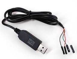
The most important point to note here is that both types use the same FT232R chip. Also, the driver installation and working procedure is the same for both. Therefore, you can use any one of these modules available with you.
FTDI USB to Serial Cable Pinout Diagram
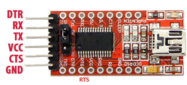
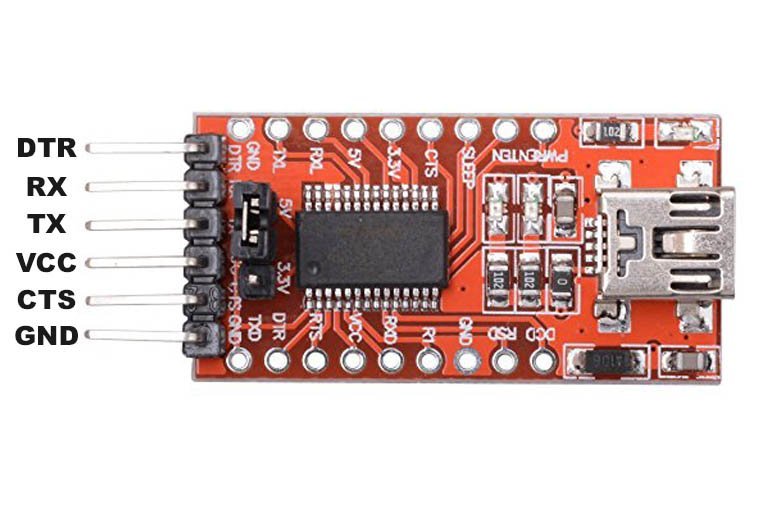
The following figure shows the pinout diagram of the FTDI USB to RS232 converter. It consists of 6 pins. But mostly four pins are used to connect UART based devices with the computer through this FTDI cable. Out of these four pins, two are power supply pins such as Vcc and GND. Two other pins are Rx and Tx Pins.
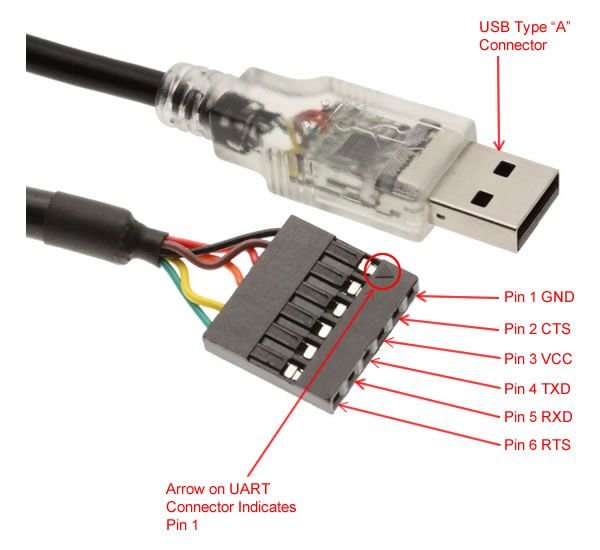
The other side of the FTDI cable is just a type-A USB connector. You can simply plug it into your computer or laptop.
Pin Configuration
Now let’s first see the pin details of serial side device. Following are the details and functionality of all pins.
- Back (GND): Connect to the ground pin of the device to which you want to connect with the computer
- Brown (CTS): Clear to Send = This is control input and is used to clear the send request of Data.
- Red (Vcc): Connect it with Vcc
- Orange (TxD): Transmit Asynchronous Data = This is an output pin and used to transmit output data asynchronously
- Yellow (RxD): Receive Asynchronous Data = This is an input pin and used to receive input data asynchronously.
- Green(RTS): This is a control output pin and is used to make a request for sending the data.
USB Connector Pin details
Inside USB F 1001 a USB series “A” connector is used to make a connection to a USB Host or computer. This is a USB 2.0 device.
The detailed description of these pins is as follows.
Power : This is a power pin and used to provide power from upstream USB Hub or HOST.
- D-: This is a bidirectional pin and is used as a data signal for USB. It has negative polarity.
- D+: This is a bidirectional pin and is used as a data signal for USB. It has a positive polarity.
- Ground: This is a power pin and provides a ground signal of power from a USB Hub or HOST.
- Shield: This is sheet outside the connector and used to prevent electromagnetic interferences from other devices to prevent data from manipulation. This is connected to the case of the host PC.
We do not need to worry about these USB pin details. Above information is provided just for your information.
How to use FTDI USB to Serial Converter?
In this section, we see a demo to use FTDI cable to transfer data between the HC-05 Bluetooth module and computer using this USB to serial converter. First, make connections with the HC-05 Bluetooth module and FTDI cable according to this schematic diagram.
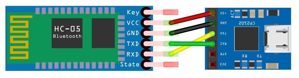
In this connection diagram, we connect a Tx pin of HC-05 with RxD pin of FTDI cable and Rx pin of HC-05 with TxD pin of FTDI cable. Also, connect GND a pin of FTDI with GND pin of HC-05.
FTDI Driver Installation
Now plug USB cable with your laptop or computer. Next step is to install drivers for FTDI chip. On latest operating systems, such as Windows 10 or Linux Ubuntu, device drivers will be installed automatically when you plug USB into computer.
But if drivers do not install automatically, you can download the drivers from this link:
On Linux based systems, drivers will be installed automatically. After installation of drivers, we need a desktop application to send and receive data from a device which we will connect with the computer. You can use any serial terminal device such as Putty and serial terminal. We will be using Putty in this tutorial.
Download Putty from this link and install on your Windows based system.
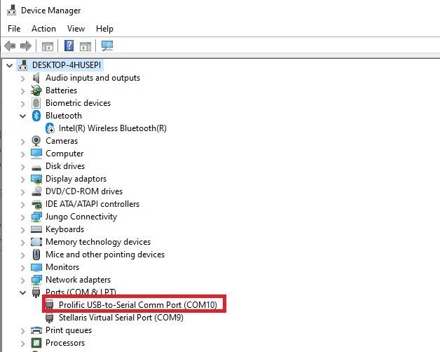
After downloading and installing Putty, connect the FTDI cable with your computer. Open the device manager and find the name of the COM pin in the ports list. Note down this port name, we will need it, later on, to connect Putty with USB to the serial converter device.
Now type “Putty” in the Windows search bar and run it as an administrator.
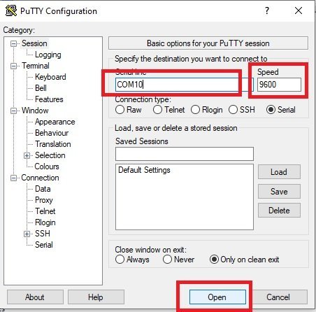
After that configuration window will appear, select the COM port and set the baud rate to 9600 and COM port number which you noted in earlier steps. Now click on the “Connect” button.
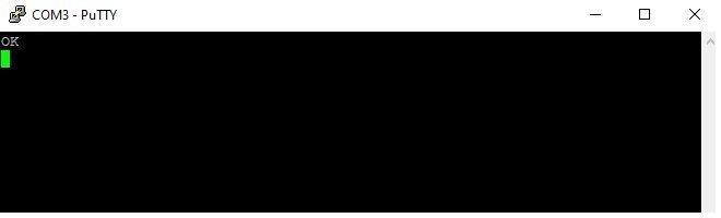
This black color console window will appear. That means we have successfully made a connection with an FTDI device.
Now type “AT” on the console, the HC-05 Bluetooth module will respond with “OK”. This shows that we are able to communicate with an HC-05 Bluetooth module using USB to serial FTDI cable.
Similarly, we can use a USB to serial converter to connect RS232 based devices with computer.
How to use FTDI cable in Linux?
In Linux Ubuntu, when you plug the FTDI cable with a computer, FTDI drivers will be installed automatically. If you have installed an Arduino, FTDI drivers will be installed automatically along with Arduino IDE on your system. Because the Arduino IDE comes with the FTDI drivers bundle.
Next step is to find the port location of the connected FTDI cable. To find a port number, type this command in the Linux terminal:
dmesg | grep FTDI
Similar to windows, there are many serial terminal options available in Linux such as Putty, minicom, etc. Because we are using Putty in this tutorial, you can install putty by running these commands in the Linux terminal.
It will show you all the FTDI devices connected with your computer. But currently, we are using only one FTDI cable. Hence, it will show its name and port location like this (/dev/ttyUSB0). Note down this port location.
sudo apt-get update
sudo apt-get install -y putty
Now type this command in Linux terminal to Launch Putty.
sudo Putty
Features of FT232R chip
The key feature of FT232R IC which comes with US232R to RS232 converter cable.
Integrated EEPROM
In older generation FTDI USB UART devices, an external EEPROM is used incase device were to use product description string, USB vendor ID and product ID other than default values. But in new designs this external EEPROM chip is integrated inside this cable which enables the cable to change product description string as per requirement. This EEPROM is programmable without any additional voltage requirement.
Preprogrammed EEPROM
FT232R comes with pre-programmed EEPROM with a unique serial number in order to eliminate the requirement to program the EEPROM of each individual device.
Lower Operating and Suspend Current
The suspend current is around almost 70 micro amperes and operating current to 15mA.
Low USB Bandwidth Consumption
This cable has been designed to use the least possible bandwidth of HOST or Hub controller.
UART Pin Signal Inversion
Setting in internal EEPROM can be used to invert the sensing signal for each UART pin. So TXD active high can be changed to TXD# active low signal.
Programmable Receive Buffer Timeout
This timeout is used to flush the remaining data from the receive buffer. This timeout is programmable from 1ms to 255 ms with an increment of 1 ms and the default time is 16ms.
Baud Rates
All standard and non-standard baud rates are supported from 300 to 3 Mbaud.
FTDI FT2323R
This block is responsible for conversion of USB format data to serial format. In order to provide serial functionality of virtual COM port FT232R requires to install operating system device driver.
RS232 Level Shifter
RS232 devices require signals in voltage levels. So this block is used for converting FT232R signals into voltage levels.
USB to Serial FTDI Cable Applications
- USB to serial RS232 converter
- Transfer low bandwidth data and USB audio data between computer and external devices
- USB smart card reader
- Used to interface Serial devices with USB hub of computer
- Low PC to USB communication
- Used to configure modules with PC such as Bluetooth, GPS, SIM900 GSM, ESP8266, ESP32 and RFID readers through AT commands
- USB barcode reader
- PDA to USB data transfer
Related Tutorial which uses FTDI Cable:
That is a very helpful article, thanks for providing it!
I intend to use a home constructed FTDI to USB converter to connect my Victron solar charge controller to my PC.
However, the RS232 levels at the controller are not 5volt. (normal for RS232) do I need to use a level shifter and if so what is the best way of doing this?
Thanks for. Your time and work!
Note there are two different things here. RS2323 applies to the hardware interface, most importantly the voltage. 0 is represented as 3v to 25v, 1 is represented as -3v to -25v. The asynchronous serial protocol is just 1’s and 0’s and the FTDI device creates a virtual port over USB that maps the 1’s and 0’s to 0 to 3.3v (or 5v).
If your solar controller has a ‘real’ rs232 interface you will need to add something like the MAX232 chip that can convert the 3.3 or 5v of the FTDI chip to the +/- voltage requires by the RS2323 spec. It does not matter what voltage on the RS232 side is used as the spec requires all values from +/- 3v to +/-25 to be handled. The bigger the voltage swing you use the longer and more reliable the cable can be.
I spent days trying to figure out if my FTDI USB/Serial cable was the right one, but this is the only site I found that has a picture with the functions shown on it. I notice that in order to run Putty on my Raspberry Pi-4b I had to use suto putty (the P is lower case, not upper case as shown on the page). Thanks for getting me on the right track.
Me gustaría saber si este tipo de cables usb se podría usar para ver mi cell a través de mi tv espero sus comentarios gracias