28BYJ-48 is a uni-polar 5V stepper motor that takes electrical signals as input and rotates by converting these input signals into the mechanical rotation. It consists of 4 stationary coils rated at +5V. These coils are known as a stator and make a ring around the rotor. It has a 1/64 reduction gear set and therefore moves in precise 512 steps per revolution. These motors are silent in comparison to other DC motors and servo motors. You can achieve positional control easily without needing extra circuitry and components.
28BYJ-48 5V Stepper Motor Pin Configuration
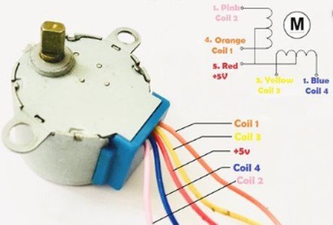
You can see from the diagram given below 5 wires are projecting out from the motor. Among them, red wire is for voltage supply. It is connected to the +5V supply. The remaining four wires are of four static coils. This picture shows a pinout diagram of 28BYJ-48 5V Stepper Motor.

Stepper Motor Features
The specifications of the S8BYJ-48 stepper motor are:
- It is a unipolar 5 pin coil with a rated DC voltage of 5V.
- It has 4 phases with a stride angle of 5.625°/64.
- The frequency of this stepper motor is 100Hz and insulated power is 600VAC/1mA/1s.
- The half-step method is recommended for driving this stepper motor.
- The value of pull in torque for a stepper motor is 300 gf.cm.
Where to use 28BYJ-48 Stepper Motor pinout?
The stepper motor is silent and provide more increments per rotation. Therefore, you can use this motor in driving display turntables and surveillance cameras. Due to its capability of providing positional control, you can use this stepper motor in the tracking of objects. If you need both rotation and positional control, then you can use this stepper motor. You can use this motor in 3D printers for precise positioning. It can be easily controlled with any microcontroller such as an Arduino.
Other Motors
How to use Stepper Motor with Arduino?
This motor has four coils which are powered in a sequence. The stepper motor consumes high current therefore a driver IC is required along with a microcontroller or Arduino. The ULN2003 breakout board has high current and voltage than a single transistor and therefore it can drive a stepper motor easily by enabling a microcontroller. The connections are simple. Connect the output pins of the driver IC with the four coils of the stepper motor and supply a positive voltage at the red wire of a stepper motor.
Interfacing with Arduino
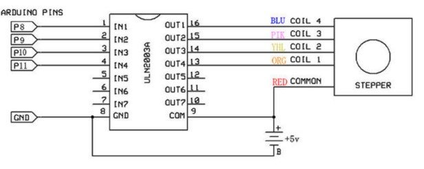
Connect the digital pins of Arduino with the input pins of the ULN2003A driver IC. You can use the full step method for rotation, but half step method is recommended for rotation of this stepper motor. In the half-step method, coil 1 is powered first. After then supply power to both coil 1 and coil 2 together. Then supply power to coil 2. Follow the same sequence in the next steps.
Switching Sequence Table
The table is given below for half step switching sequence.
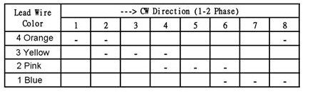
In the case of a full step method, 2 coils are provided with power at each step. The coils should be powered in a logical sequence mentioned in the table. This sequence can be programmed using any microcontroller. You can use this motor in designing projects using raspberry pi and Arduino etc.
28BYJ-48 5V Stepper Motor Applications
- They are used in cameras for providing precise control and positioning.
- The 28BYJ-48 stepper motor provides excellent control of speed during rotation. That’s why it is used in robotics projects and applications related to automation.
- The tilting of car side mirrors can be controlled using these motors.
- Surveillance cameras and DVD players are also their applications.
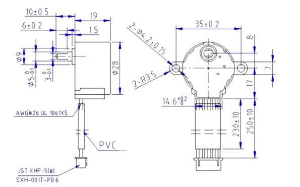
2D Diagram
The two-dimensional diagram showing all the dimensions of this stepper motor is given below.