CD4020B IC is a CMOS logic-based 14 stages Binary Counter/ Divider belonging to a CD4000 series of integrated circuits. This binary counter IC is composed of Master-Slave flip-flops with fourteen buffered outputs, a common Reset, and clock input. Unlike other counters ICs, its transition occurs on the negative edge of the clock cycle. It has a wide operating temperature range of – 55 °C to + 125 °C. CD4020 is available in 16-pin packages of PDIP, CDIP, SOIC, TSSOP.
CD4020B Binary Counter Pinout Diagram
This picture shows a pinout diagram of binary counter/ divider. Q2 and Q3 pins are not available to get output. Only pins Q1, Q4, Q5, Q6, Q7, Q8, Q9, Q10, Q11, Q12, Q13, Q14 provide binary outputs depending on the timing. We will see this in later sections of this article.

Pin Configuration Details
As you can see from the above pinout diagram that CD4020B consists of 16 pins. Out of these sixteen pins, 12 pins are binary decoded output pins. Two pins are clock and reset.

| Pin_Number | Pin Name | Description |
|---|---|---|
| 10 | Clock | We can provide a clock pulse to the IC as an input signal with this pin. |
| 11 | Reset | Reset pin is an input signal which is applied to reset the counter value. |
| 1, 2, 3, 4, 5, 6, 7, 9, 12, 13, 14, 15 | Output Q1, Q4, Q5, Q6, Q7, Q8, Q9, Q10, Q11, Q12, Q13, Q1 | Buffered output signals. |
| 8 | Ground () | This pin connects to the negative power supply or ground of the circuit. |
| 16 | Vdd | This pin is connected to the power supply. |
CD4020B Features
- Buffered inputs and outputs
- Counting range: 0 to 16383 (In decimal)
- Schmitt triggered input pulse which allows unlimited rise and fall times
- Fully Static and medium speed operation of typically 8MHz at = 10V
- Voltage Supply Range: 3V to 18V
- High noise immunity of 0.45
- Common Reset pin
- High Voltage Type (20V Rating)
- Maximum Clock Frequency: 3.5MHz at 5V
- Reset Propagation Delay: 140ns at 5V
Alternative options
CD4040, CD4060, CD4022, CD4026, CD4020, CD40103, CD4017, 74LS90, 74LS93
Where to use CD4020?
This IC is suitable for use in time-related applications that require low power and wide voltage supply range as it is a binary counter having a counting range of 0 to 16383 in decimals. It is useful for creating time delays and in dividing astable frequencies.
How to use CD4020?
The CD4020BB IC counts the input clock pulses and displays them on the output pins in binary form. This IC has a simpler circuit design due to the increased fanout and is easy to use. The constant and continuous clock pulse signal is generated at pin 10 through 555 timers or any other digital logic IC. Pin 8 is connected to the ground of the circuit and pin 16 to the positive power supply.
On every negative transition of a clock pulse, the value of the counter is incremented by 1. You can see the change in vales by connecting output pins with LED. The reset pin is used to reset the counter value to start counting from 0. A HIGH input signal at the reset pin will reset the counter value. This pin is normally connected to ground. The truth table is shown below which indicates the effect of the RESET button and clock pulse.
| CLOCK | RESET | OUTPUT |
|---|---|---|
| Positive edge | 0 | No change in counters value |
| Negative edge | 0 | Counter value advances by 1 count |
| X | 1 | All outputs are forced to 0 state. |
After connecting all the pins, switch ON the power supply.
Timing Diagram
The timing diagram shown below indicates the effect of the clock pulse signal on the 12 outputs. As you can see from the timing diagram, the time interval at which a specific pin will become high, depends on the clock frequency. We can calculate this time interval by this formula:
Time period = 2^n/f
Where f is a frequency of clock input and n is a number of the output pin. For example, for Q12 n=12.

When the CD4020 counter reaches its maximum value, it will reset automatically and start counting from 0 again. For higher decimal counting, you can cascade multiple IC’s together according to your requirements.
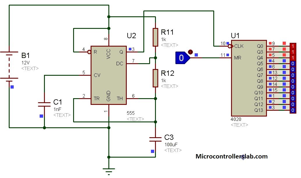
Example Circuit

Proteus Simulation
CD4020B Applications
This IC has multiple uses. It can be used in:
- Controlling counters
- Counting application for example timers
- Frequency dividers
- Time-delay circuits
- Incrementing memory addresses
- Synchronous sequential circuits
2D Diagram

DataSheet
Other Electronics Components: