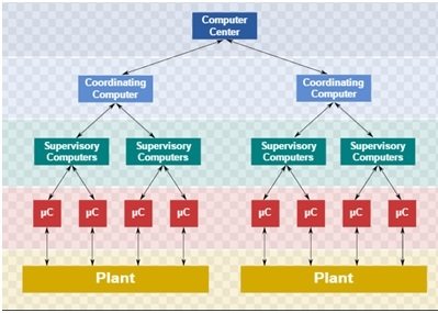
Efficient Energy Management System with Smart Grid: Efficient Energy Management System was inspired by Supervisory control and data acquisition (SCADA). Efficient Energy Management System with Smart Grid basically controls, monitors loads and power flow. It also provides protection to loads.We usually have some critical and non-critical loads. Critical loads should never be turned off. Non-critical loads can be turned on or off depending on Power consumption and supply. In home, we have infinite supply by main grid. But power consumption is limited by current enduring limits of supply wiring. When user turns more loads on, current flowing into main wire increases. If user continues to turn more and more loads, then a limit is reached where current exceeds wiring capacity causing fuse to burn or circuit breaker to open the circuit. But switch all loads off if current limit exceeds is not a good idea. Here our efficient energy management system comes to play a pivotal rule.
Need of Efficient Energy Management System with Smart Grid
Fundamental of this project is to measure voltage and current through each load. All other manipulations are done with the help of current and voltage. For example, by measuring load through each load and then adding up all currents, we can measure power consumption by all appliances. This process can also be used to switch off non critical loads if power consumption exceeds user defined limit. So, in this way we can only switch our non-critical loads off rather turning our whole home into dark by burning of fuse or open circuit by circuit breaker. Here a tiny microcontroller comes to rescue.
Working of Efficient Energy Management System with Smart Grid
Voltage measurement:
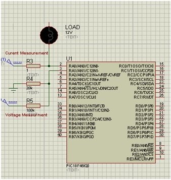
First task is to measure voltage of main supply. We can’t do it by direct using ADC. ADC can’t read more than 5V. So, we have to design our circuit in such a way that it reads less than 5V but later it converts into main voltage using coding done in microC. So, here a potential divider helps to sort this problem out. We choose our resistances in such a way that it gives near approximation.
Although this picture is taken from google, but we implemented same circuit with resistance values 20K and 100K. We measure voltage around 20K which is always less than 5 if input voltage is less than 25. We used 12V as input.
Current Measurement:
2nd task was to measure current. As we know, for accurate measurement of current by ammeter, resistance of ammeter should be as small as possible not able to change circuit current. Special shunt resistance are available for that purpose. Since, in our small energy management system, current was more than 1 amp, current readings made by 1 ohm shunt resistance connected in series weren’t accurate.
Special Hall sensors are available for that purpose but we don’t think they are available in ee lab.
Shunt resistance actually measure voltage drop around resistor, and then knowing the value of resistance, current is calculated using Ohm’s Law.
Controlling Relay:
After measuring voltages and current, we next step is to control load using relay with help of microcontroller. The circuit is given below. It is taken from google but we implemented same circuit.
It looks a bit complicated but it works in fairly simple way. When microcontroller generates high signal depending upon current and voltage detected by ADC, this high signal comes at transistor gate and then turns on transistor. A high current started flowing and energizing relay to change its connection from NC to NO. When this high signal generated by uC stops, transistor turns off. So, current flowing through relay coil stops de-energizing relay changing its connection from NO to NC. Flywheel diode is used to suppress voltage surges when relay is energized.We use this circuit to switch on and off our loads. (Note: We used NPN BJT not Mosfet in our project).
Complete circuit of Energy management system using pic microcontroller
We used 3 loads. We decided a complete mini wiring systems for connecting loads. 2 loads were fans which draw almost 0.2-0.3A current. A dc bulb draws 1.3A current. All loads were of 12V. One fan was critical. It should have turned on always. Other fan and bulb were non-critical loads. It means only one of them could be turned on at one time.We measured current through bulb using ADC. In actual, we should measure all currents but our ADC couldn’t able to handle more than two ADC inputs. It gave ‘demo limit’ error. So, we restricted it to two ADC inputs. One input was voltage of supply, other was current of bulb because almost 80% current was drawn by bulb.
We measured current through bulb, if it was greater than 1A, we turned off one fan (If it was switched on by user) and if current was less than 1A (bulb off), we switched on one fan (If it was switched on by user).So, in this way, we tried to show that how can we control loads and flow of power by merely measuring current and voltage and then taking help from microcontroller.
Smart Grid for Energy management system
We also used smart grid feature. We used another supply as UPS. And if one of the supply was active, circuit worked properly.
Difficulties and Future Aspirations:
In ideal case, we should measure total current flowing through loads rather than measuring current through one load (but heavy). First problem in doing so was ADC, which wasn’t working properly and allowing us to taka more than 2 inputs. 2nd problem was current measurement using 1 ohm resistor.We couldn’t get what we were hoping or desired. But in future, we would work on its monitoring part further using Arduino rather than PIC.
Schematic diagrams of Energy management system
Our Project doesn’t have large schematic files. It was a hardware project repeating same blocks.
Voltage, current Measurement:


Kindly provide complete circuit diagram of the project.
hi, I want a full ckt connection!!!!! to improve it with AI… I WANT TO INTERFACE THIS WITH AI AND GOOGLE ASSIST AND CHAT GPT… SO SAND ME CKE DIA…