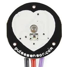
What is Heart Rate Pulse Sensor Amped? Heart rate pulse sensor amped is a such type of sensor which is mainly used for sensing heartbeat rate. Normally it is very difficult task to measure the exact heartbeat rate, but this have become so much easy with the help of this pulse sensor amped. If we talk about heartbeat, then heart beat is a periodic signal that is produced by any software or hardware system for giving intimation to normal of working of any system. For measuring this periodic intimation signal, so many sensors have been using currently in market but here we shell only talk about pulse sensor amped. This is basically plug and play heartbeat sensor and have been using by makers, athletes , game developers and students in their hardware projects. It is easily available in market or online shop. A simple heartbeat pulse sensor is shown in figure 1,
Figure 1 A Simple Heartbeat Rate Pulse Sensor
Pin Configuration of Heart Rate Pulse Sensor
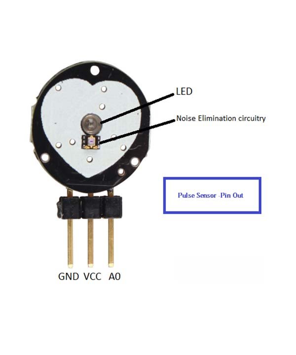
Every heart rate sensor consists of three pins first one is ground pin which is used for supplying ground to this sensor and it is connected to source ground pin .Second one is VCC pin which is used for power on this heart rate sensor and it is connected to source VCC pin. This sensor is powered on at almost 3.3V to 5V dc voltages. Similarly, the last one is A0 pin which is an analogue pin and it is used for receiving analogue signal. The pin configuration of this heart rate sensor is shown in figure 2
Figure 2 Pin Configuration of Heart Rate Pulse Sensor
According to figure 2 this sensor also consists of a central LED. This LED helps the sensor for detecting heartbeat rate. Beside this, there is another circuitry below LED and this circuitry is called noise elimination circuitry. This circuitry is used for eliminating the noise which effects on the reading of the heart rate pulse sensor.
Working Principle of Heart Rate Pulse Sensor
The working principle of this heartbeat rate sensor is very simple. If we talk about heartbeat rate, then heartbeat rate is the ratio of time between two consecutive heartbeats. Similarly, when the human blood is circulated in human body then this blood is squeezed in capillary tissues. As a result, the volume of capillary tissues is increased but this volume is decreased after each heartbeat. This change in volume of capillary tissues, effects on the LED light of heart rate pulse sensor, which transmits light after each heartbeat.
This change in light is very small but this can be measured by connecting any controller with this pulse sensor. Means, the LED light which have every pulse sensor helps for measuring pulse rate . The working of this sensor could be checked by placing human finger in front of this pulse sensor. When finger is placed in front of this pulse sensor then the reflection of LED light is changed based on the volume of blood change inside capillary vessels. Means during heartbeat the volume of blood in capillary vessels will be high and then will be low after each heartbeat. So, by changing this volume the LED light is changed. This change in of LED light measures the heartbeat rate of finger.
How to Interface Heart Rate Pulse Sensor with Arduino Board
For measuring the heartbeat rate with the help of heart beat rate sensor, a controller is necessary to interface with this heart rate sensor. Here we shell tell the user how interface the Arduino board with pulse sensor module. Check this article on heart beat sensor interfacing with pic microcontroller.
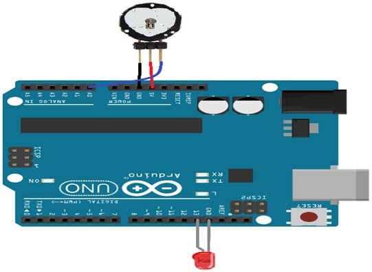
First of all, connections are made according to figure 3
Figure 3 Interfacing of Heart Rate Sensor with Arduino Board
After making connection, for checking output of this of this heart beat rate sensor, a LED is connected at output of Arduino board. Whose power pin is connected to pin 13 of Arduino board and ground pin is connected to ground pin of Arduino board. Then logic program is written in Arduino board liberty and then up load with the help of Arduino IDE software. When it is powered on and program is run then output LED is blinked according to heartbeat rate.

