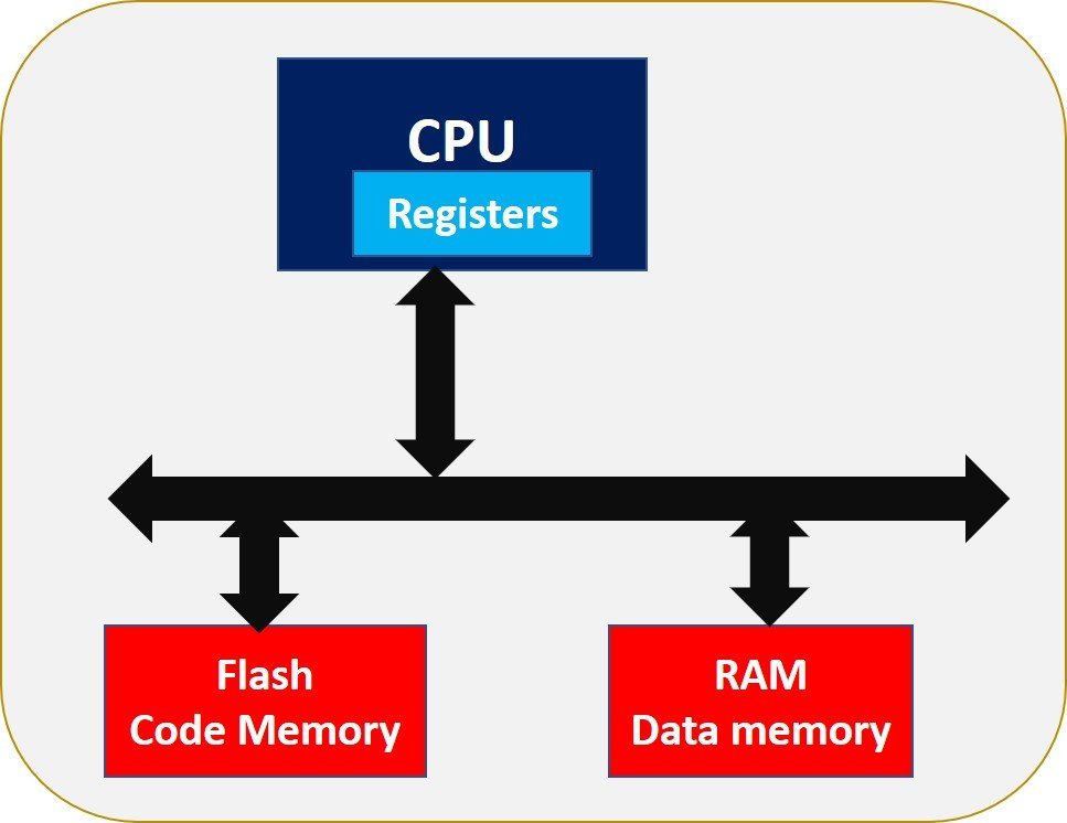
In this tutorial, we will see the memory organization in microcontrollers. Firstly, we will discuss the different types of memories that are available in microcontrollers. After that, we will go through different compiled memory sections of the program and data memory. We will see how different compiled memory sections store in the physical memory of microcontrollers. This will help you to understand how different memory sections are organized in microcontrollers.
In microcontroller based bare metal embedded systems, memory is a resource constrained key component. Because microcontrollers come with a limited amount of memory. Hence, it is a limited resource and we should use it efficiently.
Memory Introduction
Computer memory stores every information in the form of bits either zero or one. Hence, the main basic component of memory is a bit. But memory is usually organized in bytes. One byte consists of 8 bits. Therefore, one byte is the minimum information that microcontrollers can read and write. In other words, every memory location is byte addressable. That means, each memory location consists of one byte and each location has a unique address. Hence, memory is organized in the order of hundreds and thousands of bytes.
Unlike desktop computers, microcontrollers have limited amounts of memory usually in the range of hundreds of kbytes to Mbytes. For example, if we take the example of TM4C123GH6PM microcontroller which comes with Tiva Launchpad, it has on-chip 256K bytes of flash memory and 32K bytes of RAM memory . But microcontrollers vendors provide different microcontrollers having different memory ranges.
Note: Before selecting a microcontroller for your project, you should choose a microcontroller according to the required memory size for your embedded application.
Types of Memory used in Microcontroller
Mainly, microcontrollers have two types of on-chip memory such as flash memory and data memory. But, microcontrollers also have a limited amount of EEPROM which is used to store data permanently even if the power is lost.

Flash Memory ( Non-volatile)
Flash memory is a non-volatile memory and it holds our embedded application program code and some data. This is also known as code memory. Code memory is usually larger than RAM memory. Because flash memory contains our program code and code size is typically larger than the program data. Moreover, once the microcontroller is programmed, the memory space is reserved for the application code in flash memory and this memory space cannot be overwritten during program execution and can be overwritten only once the device is reprogrammed. But during program execution, this memory space has only read only permission. But RAM memory can be overwritten by many parts of application data during program execution.
RAM Memory (Volatile)
RAM memory holds different types of program data such as temporary variables, global variables, program stack and heap sections. RAM memory in microcontrollers is usually lesser in size than flash memory. One of the reasons is discussed in the last section, the other important reason is that RAM memory has lower latency than flash memory. That means RAM speed is faster than flash memory. The cost of RAM memory is higher than flash memory. Therefore, RAM size is usually lesser than flash memory in microcontrollers.
CPU Registers (Volatile)
CPU registers hold operands, instructions addresses, run-time state of the program. CPUs have two types of registers such as general purpose registers and special function registers. General purpose registers hold values of the operands on which CPU wants to perform operations such as addition, subtraction, multiplication etc. On the contrary, special function registers, such as program counters, main stack pointer, instruction pointer,etc, define the state of the program.
In summary, code memory, data memory and CPU registers are the main three types of memory resources available in microcontrollers.
Memory Organization in Microcontroller
In order to better understand memory organization in microcontrollers, you should first know about the format of microcontroller’s executable programs or the code that we upload to flash memory of microcontroller. You can check this tutorial on bare metal embedded systems build process:
Bare metal embedded systems build process using GNU toolchain
Flash Memory Layout
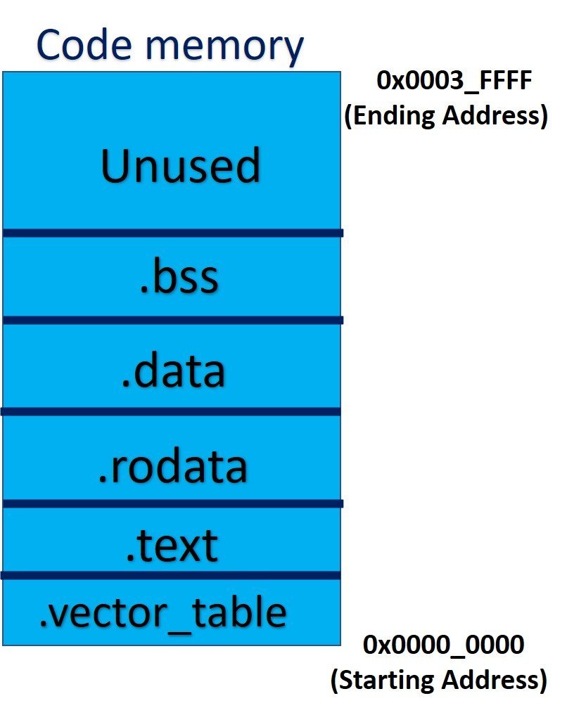
Microcontrollers flash memory contains different segments of application code such as, interrupt vector table, code segment, initialized data segment, uninitialized data segment, constant data segment etc. The linker script file which is used in the embedded system build process defines where each of these segments will store in flash memory. If you don’t know about the linker script file, you can read this tutorial:
Role of Linker script file in bare metal embedded system build process
The linker script specifies where these different sections of the code segment will map inside physical flash memory.
In order to explain the memory layout or memory organization of the code segment, let’s take an example of TM4C123G microcontrollers. Code segment and sub segments of main output file of TM4C123G microcontroller are stored in flash memory according to the layout as shown in figure below:

The size of flash memory and starting/ending address depends on the target embedded device.
Interrupt Vector table Segment
This sub-segment of code memory contains the addresses that point to different interrupt and exception routines such as reset handler. It helps NVIC to find starting addresses of interrupt service routines. If you want to know what happens when a microcontroller resets, check this tutorial:
Microcontrollers reset sequence
Text Segment
The text segment contains our main application code such as program instruction, interrupt service routines, user-defined functions, microcontroller startup code, and standard library functions. In simple words, it contains our actual microcontroller application code that we have written. This segment has read-only permission. That means CPU can only read instructions from this segment but cannot perform write operations.
.rodata Segment
The .rodata section contains the constant type of data that we defined in our program such as strings, constant variables, etc. This section is also referred to as .const.
For instance, these two variables will store in .rodata section of memory:
Const int x= 10;
Const char var = ‘A’;
Note: The constant data once defined during program compilation can not be changed during program run-time. Doing so will throw an exception.
.data Segment
The .data section contains global, global static, and local static variables of program data.
.bss Segment
The .bss segment contains uninitialized global, global static, and local static variable data.
This is how different compiled sections of program maps to the physical flash memory of the microcontroller.
RAM/Data Memory layout
Data memory consists of .data section, .bss section, stack and heap. First of all, whenever a microcontroller boots up, .data and .bss sections (that are defined in the last section) copy to RAM memory. Also heap and stack memory area is assigned to stack and heap sections inside the data memory. A startup file performs all these hardware initialization steps.
We have posted a complete in-depth guide on the role of startup file in microcontroller:
Startup file in microcontroller
In summary, code and data memory are two main types of memory used in microcontrollers. CPUs also have internal registers that are used to hold data temporarily and define the state of the program. The memory organization in microcontrollers helps to use memory efficiently and effectively.

I’d always want to be update on new posts
on this website, saved to bookmarks!
thanks for sharing! it is a good tutorial for memory organization in mcu.