ST7290 GLCD module is a simple graphical display using liquid crystals. It supports officially both parallel and serial communication to the Arduino. Other microcontrollers also able to operate the LCD with the use of three control pins and eight digital pins, which makes parallel communication. Led uses the back light-blocking method to display the data. There is a total of 128×64 pixels on the whole ST7290 GLCD. Therefore, we can display images of 128×64 resolution but data should be in the hex format. The limitation of one color doesn’t allow us to show the other formats. Furthermore, it has internal controllers and registers which makes it easy to understand and use without even use of libraries.
ST7290 GLCD Pinout Diagram
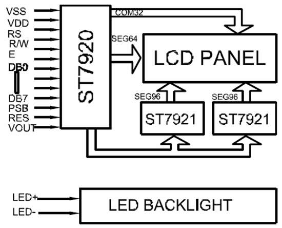
This is a pinout diagram of this graphical display.


Pin Configuration Details
The pin configuration of the ST7290 GLCD is almost the same as other LCDs. Even most of the functions of the ST7290 are the same as other LCD pins. There is a total of 20 pins, which gives serial and parallel communication features. We provide functions of all the pins in the preceding sections:
Power Pins
| PINS | DETAILS | |
|---|---|---|
| Pin1 | GND | Pin1 is a ground pins for common ground with power and control devices. |
| Pin2 | VCC | VCC uses to input the power of the internal register and control circuits, etc. |
| Pin3 | Vout | This pin generates the voltage but as a double. |
ST7290 GLCD Control Pins
| PINS | DETAILS | |
|---|---|---|
| Pin3 | Vo | The GLCD uses the blocking of backlight for visual display. The blocking of light intensity is adjustable with this pin. |
| Pin4 | RS | The RS pins help to decide the internal registers between the command and data. |
| Pin5 | R/W | The R/W pins help to decide, whether the GLCD is going to read from a microcontroller or write. |
| Pin6 | E | This pin is an enable pin, which enables the data from instructions and data registers to the GLCD. |
| Pin15 | PSB | The PSB will decide whether GLCD is going to use parallel or serial communication. |
| Pin16 | NC | It’s a no connections pin |
| Pin17 | RST | The RST pins help to reset all the displays on the LCD and data within itself. |
GLCD Parallel Input Pins
| PINS | DETAILS | |
|---|---|---|
| Pin7 | DB0 | These are the digital input data pins for parallel communication. It can also operate with only 4 specific digital pins, which are DB4-DB7. |
| Pin8 | DB1 | |
| Pin9 | DB2 | |
| Pin10 | DB3 | |
| Pin11 | DB4 | |
| Pin12 | DB5 | |
| Pin13 | DB6 | |
| Pin14 | DB7 | |
Backlight Input Pinout
| PINS | DETAILS | |
|---|---|---|
| Pin19 | BLA | The BLA pins are the Power input pin of the backlight LED. |
| Pin20 | BLK | The BLK is a ground pin of the internal LED. |
ST7290 GLCD Features
- It can display data up to 128×64 pixels.
- GLCD has external voltage double pins, which can double the voltage up to 7V.
- It supports both serial and parallel communication methods.
- The integrated driver ST7290 makes it easy to drive the whole LCD.
ST7290 GLCD Applications
- The ST7290 GLCD Display has vast applications in the digital display of data.
- Most of the calculator uses the ST7290 controller display.
- Pocket Games
ST7290 GLCD Construction
The whole GLCD is made up of small 128×64 pixels. Each pixel is made up of 5 small layers. The outer most layer is known as the protection layers. The other three-layer make each pixel on the LCD Screen. The inner layer two layers make the sandwich of liquid crystals. The layers have polarized path opposite each other. The polarized layers also act as anode and cathode. When the light passes from them, they stop it because it’s their pattern. When the power applies to the polarized layers then the crystal changes their direction and lets the backlight go through itself. The dark pixels stops the light because they weren’t getting the light. Each pixel will control by the driver ST7290.
ST7290 GLCD Driver
The driver has multiple pins, the main input pins are 18 which are already been discussed in the Pin Configuration. The rest of the pins connects with the pixels in the form of row and column. The output pins are 128X64 in numbers and they control every pixel. The driver has internal registers, which act as data and instructions registers. Therefore, the input pins will help to control the resister and these pins will make the data display on the GLCD. both types of registers are controllable through the RS pin. The data registers get fill and then show the data. To replace the data on the screen the data register needs to replace with new data. So always clear the LCD the previous data before replacing the new data. The command registers are also needed to replace the data but only the opposite in functions with each other.
How to use ST7290 GLCD Module?
GLCD has two communication method which is useable to control the GLCD. We can interface it with microcontrollers with two methods. The first method is using parallel pins and the second pins are serial communication pins.
GLCD Interfacing with Arduino
This example of the LCD is mostly available in Arduino. Arduino uses the following circuit to operate serially.

GLCD Programming with Arduino
After designing the circuit, it requires the following library to operate.
#include "U8glib.h"
After initializing the library, the pins need to describe. For Serial only the following pin needs to describe in the Arduino.
U8GLIB_ST7920_128X64_4X u8g(10);
The pins 10 is the PSB pin of the LCD, which only describes the serial and parallel method. Here we will use the serial method because the parallel method is efficient with the library and also follow the same protocol. The main reason for the LCD usage is to avoid the complexity of pins and get the larger display size. The above command will only change when every LCD needs to convert from serial to parallel communication.
Clear Function
The display clear method is one of the most used methods in the LCD. If the LCD has previously stored data then it won’t show the new data clearly unless it gets cleared first.
void clearLCD(){
u8g.firstPage();
do {
} while( u8g.nextPage() );
}
The above function needs to describe to clear the data from the LCD. After describing the above function just call it in the loop whenever the LCD needs to clear.
clearLCD();
How to Display Text on GLCD?
The text display method is also the same is clear. To show any text it needs proper instructions. The instructions are given able through the function or directly in the loop. Heres the program for only text display:
u8g.drawStr( 0, 22, "Hello World!");
The first 0 and 22 describe the x and y-axis of the text position on pixels. It should be according to the resolution size of display because the value of the axis defines the text location on the screen. The next part sections shows how to display text.
How to Display images on ST7290 GLCD?
The graphical display screen has only one black color data display. If developers desired to show the image on the screen then it could happen. Only some protocols need to follow, which is the image should be in the hex format of the bitmap image. Then the following command will help to show the image.
const uint8_t rook_bitmap[] U8G_PROGMEM = {
Enter the bitmap image hex code.
};
The above array is the method to describe the image. To show the image on the GLCD, the following function needs to call in the loop/setup.
u8g.drawXBMP( 0, 0, 128, 64, rook_bitmap);
The above simple command will show the image whenever it needs to show. There are multiple other functions like font control, text intensity, etc which is useable through the programming. All other functions are available in the examples of the library.
2D Diagrams
This is a two-dimensional diagram that you may need to design a PCB.
