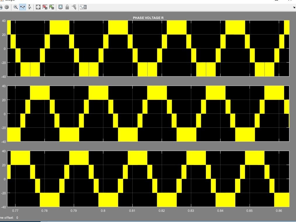
Three Phase Five Level Inverter simulation using Simulink MATLAB: A three phase five level power electronic inverter inverts the dc voltages into three phase ac voltages, because its output voltages has five levels of ac vantages means V, V/2, 0 and -V, -V/2 therefore it is called five level inverter. Normally, the speed of three phase ac motors are controlled through VFDs (Variable frequency dives) but their cost is so much high, against this, if anyone want to control the speed of three phase ac motor then he can easily control through this three phase five level inverter.
But first he should check the results of this five level inverter on MATLAB Simulink. In this article, we will be told the user, how he can make this three phase five level inverter in MATLAB using Simulink, as well as how he can make a new model for his new circuit. For making any new model, first he will open the MATLAB, the MATLAB main page has different option on their Manu bar just click on MATLAB Simulink library browser option then a new page would be opened shown in figure 1.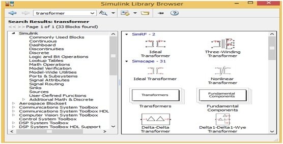
Figure 1 MATLAB Simulink Library Browser
This Simulink library browser page has different components blocks and different options on their Manu bar, the user can use any one of these blocks, but first he would have to make a new model and for making a new model the user will click on new model option. When he will click on new model option then a new blank page would be opened shown in figure 3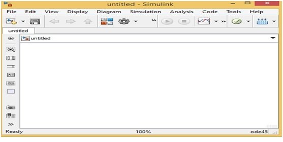
Figure 2 Figure 2 MATLAB Simulink New Model
In this new model blank page, the user can make any new circuit as per their requirement but for making a new circuit first he would have to choose the components blocks. For choosing or searching the components block, he will just write the name of that specific component on search Manu bar of Simulink library browser then all the related components blocks would be opened on a new page. Suppose, the user wants to make the three phase five level inverter, because it is made with power electronic components therefore he will just write the word power electronics on search Manu bar then a new page would be opened which have all the power electronic components blocks such as diode, MOSFET and thyristor etc. shown in figure 3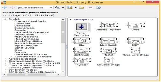
Figure 3 Power Electronics Components Blocks
These power electronic blocks could be used for making any power electronics circuit and for making any power electronic circuit just drag these blocks on a new model page or right click on any component block and then click the option at add this block to a new model then this block would be automatically drag on a new model page. Here we will not make this three phase five level inverter on MATLAB but we will explain this by using block diagram. The user can make this five level inverter on MATLAB after understanding this block diagram. The block diagram of this five level inverter is shown is figure 4,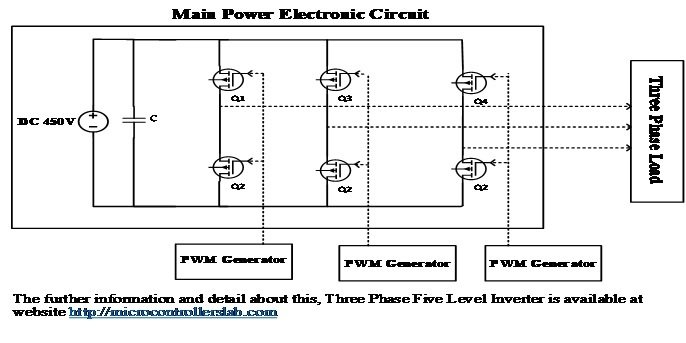
Figure 4 Block Diagram of Three Phase Five Level Inverter
In this three phase five level inverter 450V dc voltages are inverted into 440V three phase ac. For making this inverter 6 switches, MOSFET or IGBTs are required, which joined in three arms according to block diagram. Separate PWM generator is required for turning on or off the arms switches. In PWM generator SPWM (Sinusoidal pulse width modulation) technique is used for generating the PWM for these switches. In SPWM technique one low frequency 50H sine wave is compared with high frequency triangular wave then resulted wave form is used for turning on or off these switches.


Dear Author!
Can u give us the SIMULINK FILE of this simulation! Thank you so much!
Dear Author!
Can u give us the SIMULINK FILE of this simulation! Thank you so much!
Dear Author!
Can you give us the SIMULINK FILE of this simulation! Thank you so much!
Can you give us the SIMULINK FILE of this simulation! Thank you so much!