2N2222 NPN transistor has been commonly used for switching and very high frequency(VHF) amplifier applications. It is made of silicon material and specially designed for low voltage, low to medium current, and low power amplifier applications.
2N2222 NPN Transistor Introduction
2N2222 provides a continuous dc collector current is 800mA. It means it has a high collector therefore it is mostly used in that circuits where low to medium current is required. It works on a high transition frequency value 250MHz with delay time 10ns, rise time 25ms, storage time 225ms, and fall time 60ms. It is friendly to use and easily available online market in a TO-92 package.
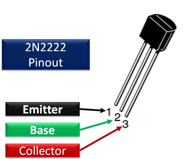
Pinout diagram 2N2222
Pin Configuration of 2N2222 NPN Transistor: This 2N2222 NPN transistor has three pins emitter, base, and collector. These pins are used in the circuit for turning on or off the transistor. Its pin configuration diagram is shown here according to the datasheet:

Pin Configuration Description
| Pin Number | Pin Name | Function |
|---|---|---|
| 1 | Emitter | The emitter pin is used for draining out the whole transistor current. |
| 2 | Base | The base pin is a control pin and it is used for controlling emitter to base current. |
| 3 | Collector | The collector pin is an output pin and it is used for providing transistor current to the output load. |
2N2222 NPN Transistor Electrical Features
- Collector to emitter voltage is VCEO = 50V when the base is open
- Emitter to base voltage is VEBO= 6V when the collector is open
- Collector to base voltage is VCBO= 75 when the emitter is open
- Dc continuous collector current is IC = 800mA
- Total device power dissipation is PT = 1W
- Maximum thermal resistance from junction to a case is R0JC= 150C0/W
- Maximum thermal resistance from junction to ambient is R0JA= 325C0/W
- Input capacitance = 25pF
- Output capacitance = 8pF
- Turn-on time = 25ns
- Fall time = 60ns
Alternative Options
Equivalents
- 2N2907(PNP)
- 2N3904(PNP)
- 2N3906 (PNP)
- BC637
- S9014
- BC148
- 2N4403
- MPS2222
- PN2222
- KN2222
- KTN2222
Where to 2N2222 NPN Transistor
- This 2N2222 NPN transistor has almost the same technical specifications as BC547 NPN transistor
- But the only difference between them is the continuous collector current and total power dissipation of this transistor
- Therefore, it could be used in that application such as switching and amplifications where BC547 transistor has been using. In switching application it works in two regions such as saturation and cut off region
- In saturation region full current flows from emitter to a collector that’s range is 110 to 800mA and in this condition, it acts as a turn on a switch. Therefore the user cannot connect the load whose current is greater than 800mA
- Similarly in the cut-off region, no current flows from emitter to collector then it acts as a turn off the switch
- A current limiting resistor is also in the circuit for limiting the base current because it could be damaged the transistor if the source current is greater than 5mA
Configuration Modes
Similarly in the amplification application, it can be connected in three configurations such as common emitter, common collector and common base. Current, voltage and power can be easily amplified by using these configuration modes.
2N2222 Example Circuits
In this section, we will discuss some examples using this NPN transistor. First, we will see an example of a simple LED controlling example with a switch. After that, we will see an example of controlling a dc motor with Arduino Uno.
LED Controlling Example
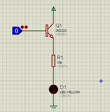
In this example circuit, we attach a push-button with a base terminal. 5 volts with collector terminal through 220ohm resistor.
- Connect an LED with an emitter terminal through a 220-ohm resistor. By mistake, 10kΩ used as a current limiting resistor with an LED.
- If you use 10kΩ LED will not glow when you turn on the switch due to low current passing through the LED.
- 10kΩ resistor will limit the current below the forward current requires to turn on an LED.
- Also, use a 220Ω resistor between the switch and base terminal.
- Now, if you apply a 5 volts logic at base input, you will see LED glowing. Otherwise, it will remain off.
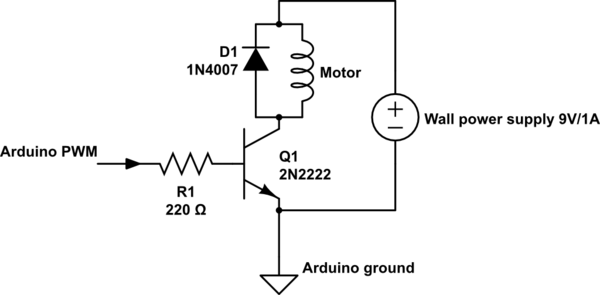
Example of Interfacing DC motor as a switch using Arduino
In this example, a 2N2222 NPN transistor is used in common emitter configuration mode. This circuit controls a dc motor through a transistor that is used as a switch. We can use Arduino Uno or any microcontroller to control this circuit. The working of this circuit is exactly the same as you have seen in the last section except dc motor is used.
You can read this tutorial for further :
Applications 2N2222 NPN Transistor
- This 2N2222 NPN Transistor could be used in that loads where current is required more than 800mA
- Motor drive circuits such as variable frequency drives (VFD) etc.
- Dc inverters and rectifier circuits.
- Darlington pair transistors where more than one transistors are connected in parallel for obtaining the high current from emitter to collector.
- It could be used as an amplifier for amplifying current, voltage, and power.
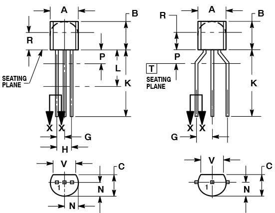
2D Dimension diagram
A 2D diagram helps while designing a PCB diagram and during electronics components assembly. You can download the datasheet for a dimension diagram of other packages.


The pinout for the 2N2222A NPN transistor shown in this article is incorrect. Quickly referencing the datasheet provided in this very article will show the pinning diagram above is wrong. Correct configuration (from left to right with flat side facing towards you): Pin 1 – Collector, Pin 2 – Base, Pin 3 – Emitter. The collector and emitter are incorrectly reversed on the pin diagram shown in this article. The datasheet configuration is, of course, correct.
Hi,
Thanks for pointing out a mistake. We have updated the articles with the correct pinout diagram.
The correct pinout for a 2n2222 transistor is pin1-emitter , 2-base, 3-collector. The problem is that the data sheet that you have linked to is for a p2n2222a transistor which has a different pinout from a 2n2222 transistor.
It’s a confusing mess, isn’t it? It seems that the transistor described in this article is actually the PN2222A and that 2N2222 strictly refers to the metal canned TO-18 version. The PN2222A has the EBC pinout, while the P2N2222A has the CBE pinout – both are plastic TO-92 packages. The Wikipedia article makes the distinction clear. With all that said, the bulk pack I have has them individually labelled 2N2222A, they are plastic TO-92 packaged and the pinout is EBC but I can’t find a data sheet that matches them exactly in terms of label, package and pinout. And these are one of the commonest transistors out there. Crazy.
The 2N2222 Pinout on this page is INCORRECT.
Dear Sir, Firstly I was confused to see your pin out mentioned! but unfortunately I didn’t follow your instructions , and I followed and act accordingly which I have used generally pin1) Emitter 2) Base 3) Collecter. I think it’s correction should be made as early as possible. Thank you.
done