1388A is an 8×8 LED matrix module, which helps to design visual display. There is a total of 64 numbers of LEDs in a total display. All the LEDs are common in Anode and cathode with each other in a pattern. The whole pattern comes out with an anode and cathode in the form of low and column. The LED pattern is designable and available in the form of the 1388A module. The module only gives the output in the 8×8 LED matrix which is expandable by combining the multiple modules. The module is useable with every microcontroller, IC and even with simple power supply without using any special programming.

8×8 LED Matrix Pin Configuration
The number of pins in the 8×8 LED matrix module is the simplest. The use of the pins may some designer find complex but its pins are just a positive input from in the ROW side and -ve input of battery from the column side. The LED power pins are common in a row and ground pins are common in the column but still a single LED is useable by applying power on a single row and column. This is a pinout diagram of the LED matrix is:
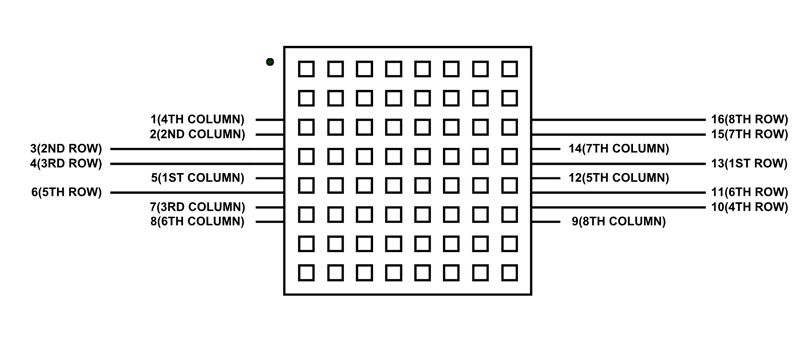
Column Pins
These pins make the column pins common ground. Each column will describe the common ground of LEDs in a column.
| PINS | COLUMN |
|---|---|
| Pin1 | Fourth Column |
| Pin2 | Second Column |
| Pin5 | First Column |
| Pin7 | Third Column |
| Pin8 | Sixth Column |
| Pin9 | Eight Column |
| Pin12 | Fifth Column |
| Pin14 | Seventh Column |
ROWS Pins
All the below pins are the common power pins of each LED. They all help to provide the power to each LED.
| PINS | DETAILS |
|---|---|
| Pin3 | Second Row |
| Pin4 | Third Row |
| Pin6 | Fifth Row |
| Pin10 | Fourth Row |
| Pin11 | Sixth Row |
| Pin13 | First Row |
| Pin15 | Seventh Row |
| Pin16 | Eight Row |
8×8 LED matrix Features
- The LED matrix is operatable from any device at LOW voltage.
- Any text or image is drawable on the matrix.
- The matrix works on the forward bias with 1.5-2V only.
- The matrix is designable by simple LEDs and doesn’t have any special requirements.
- The programming may find complex by some developers. So, there is a driver that helps to simplify the programming too.
- Scrolling, Blinking, or multiple kinds of patterns are performable on the matrix.
LED matrix Applications
- The LED matrix is mostly available in text signs.
- Most of the developers use it design snake games.
- The clock of the matrix also uses by some companies
- Most of the watches also have the matrix to make it look attractive and unique.
8×8 LED Matrix Internal Structure
To understand the LED matrix internal structure, first, understand a simple LED. The LED has two pins that use DC power to give the output as a LIGHT. In this matrix, there are 8 numbers of rows and 8 numbers of columns. It is because each LED positive pin is common with each LED in the ROW and its negative pin is common with all the LED pin are in the column with it. All row pins will connect with the positive terminal of power supply and ground of power supply will go to the column. The power on and single row and single column will turn on a single LED. For example, is power applies to a row3 and column3 then led in the matrix at 3×3 will turn on.
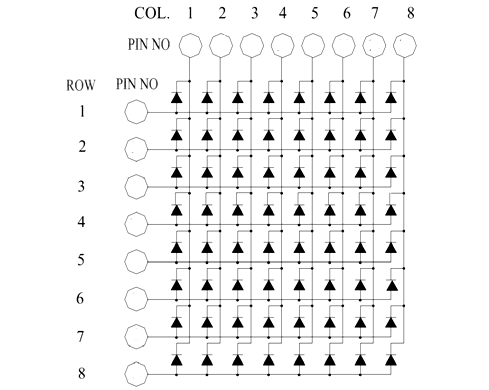
In matrix whole row can turn on by simple power on a single row but all the columns should have the negative/ground terminal of the matrix. The same process will go with the column. The LED matrix is available in the market as predesigned modules but they have a higher cost as compare to the self-designed.
How to use 8×8 LED Matrix?
The matrix is easy to use with any device. It is controllable directly by the power supply or any CMOS/TTL device. The basic requirement of the Matrix is 2V maximum. To use the matrix the 220ohm resistors should use. The CMOS/TTL devices give the output is 5V max. To minimize the volts the resistors will help. The resistors will need to connect on each row and column. To use the Matrix there are two methods, one is the driver and the second one is the direct method. The direct method is reliable and complex but here we will use the driver to show the data on the matrix.
8×8 LED Matrix Interfacing with Arduino
The driver “Max7219” uses the above circuit to operate. It requires specific programming to operate with Arduino. The Arduino has a library to operate the 1388A matrix module with the driver due to its too many applications and usage in real life.

LED Matrix Programming
To use the Module first draw the circuit according to the above diagram. Then add the following libraries in the Arduino IDE.
#include <MaxMatrix.h> // Click to Download Here
The library will make communication easy. The addition library with the driver will make the matrix to operate with 2 pins only. The total of three pins will responsible for all the row and column functions on the matrix. The matrix 1388A comes with a reattached driver. The only thing after the driver and the library needs to describe is the pins. After the following library, the pins will be described by:
MaxMatrix matrix(DIN, CS, CLK, MaxInUse);
// DIN, CS and CLK pins are the Driver pins.
//The MaxInUse pin will describe the total number of Matrix with drivers we are using. In our case, it will be two.
The above command will solve the matrix interfacing issue now just initialize it in the Arduino setup. The following command will help to initialize it:
matrix.init();  //Initialize the MAX7219 driver
matrix.setIntensity(8);   //To change the initial LED intensity. The max value is 15 and min is 0
Now the most important part is the data for Matrix. The matrix data needs to describe first in the form of an array. Here’s the example:
char smile[] = {8, 8,
B00111100,
B01000010,
B10010101,
B10100001,
B10100001,
B10010101,
B01000010,
B00111100
};
The above array consists of three parts. Therefore, the first part is the variable by which it will call further in the program. The variable part is changeable. The second part is the size of the matrix. This will decide how much part the display data is going to take. The size needs to be within the size of the matrix. Now the second part is the binary data. In binary data, each LED status is controllable by a simple command. The variable 0 will show that LED is off and 1 will turn on the LED. The above data will make the smiley face on the Matrix. The binary data can be shown by the hexadecimal.
Declaration
Now the last and the remaining part is the use of declared data on the Matrix. To use declared data the following command will help:
matrix.writeSprite(0, 0, smile);
The first two commands 0,0 are the starting point of the data. in programming, the initial point of the matrix top right corner will be 0,0 and the bottom right will be 7,7. The smile is the variable we use to store the data in the array. A single command like LCD/OLED is available here to clear the data on the matrix which is:
m.clear();
The following command will clear any kind of data on the Matrix. The above declaring command we used is for only predeclared data but there is a specific command to turn on a single LED of the matrix. The command is:
m.setDot(6,3,true);
The 6 is the row and 3 is the column of the LED. And true will make the LED glow. To tun, it off replaces the “true” with “false”. There are other functions like scrolling or blinking etc performable through the library using loops. Therefore, the library and driver can be used to build up a big signboard easily.
Tutorials
- LED matrix interfacing with PIC microcontroller
- What is Led matrix? Types of Dot matrix display with working
2D Diagram
