We all familiar with blinking LED using Arduino boards as this is the fundamental step towards using a new development board. In this tutorial, we are going to learn basic built-in commands of Arduino IDE which will help to blink LED using ESP8266 NodeMCU and ESP-01 module. If you wonder how to install Arduino IDE to interface with ESP8266 so you can find this tutorial helpful here.
Video demonstration
In this LED blinking tutorial, First we will see how to connect an external LED with NodeMCU and how to blink it using GPIO pins of ESP8266 NodeMCU. After that we will see how to blink an on board LED of NodeMCU and at the end of this guide, we will see how to use GPIO pin of ESP01 to control light emitting diode and how to program ESP01 with FTDI device.
First of all, we learn how to write sketches for ESP8266 in Arduino IDE. To write any sketch we have to learn the basic built-in functions and their syntax for this purpose visit our last tutorial on reference for ESP8266 using Arduino IDE here.
You can find more details on ESP8266 and NodeMCU GPIO pins here.
ESP8266 Pinout in Arduino IDE
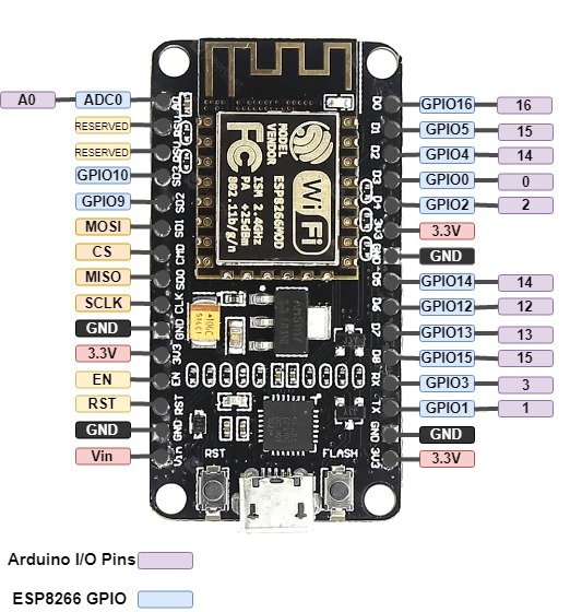
Keep in mind that labels on NodeMCU silkscreen and that use in Arduino IDE are differed from each other. Consider the following table and the NodeMCU picture to use the right number of the pin in your sketch otherwise you will face the problems in using the correct GPIOs.
| Arduino IDE Pins Index | ESP-12E | ESP8266 GPIO |
|---|---|---|
| A0 | A0 | ADC 0 |
| 0 | D3 | GPIO 0 |
| 1 | D10 | GPIO 1 |
| 2 | D4 | GPIO 2 |
| 3 | D9 | GPIO 3 |
| 4 | D2 | GPIO 4 |
| 5 | D1 | GPIO 5 |
| 12 | D6 | GPIO 12 |
| 13 | D7 | GPIO 13 |
| 14 | D5 | GPIO 14 |
| 15 | D8 | GPIO 15 |
| 16 | D0 | GPIO 16 |
Components Required
- NodeMCU ESP8266
- LED
- Resistor 220 Ohms
- Breadboard
- Jumper Wire
- Micro USB cable
- ESP01
Connection Diagram NodeMCU with LED
Make the circuit diagram on bread board according to connection diagram shown below. Anode of the LED is connected to the D1 pin of the NodeMCU, the cathode of the LED is connected with the one terminal of the resistor and another terminal of the resistor is connected to the ground pin.
Writing sketch for blinking LED
First of all, we define a variable named “LED” with integer data type to assign the GPIO we want to use, in my case GPIO5 which is labeled as D1 on NodeMCU silkscreen.
int LED = 5; // Assign LED pin i.e: D1 on NodeMCUIn void setup ( ) function, we describe the status of the GPIO pin because GPIOs act as input pins by default so we use the pinMode function to change its status.
void setup() {

// initialize GPIO 5 as an output

pinMode(LED, OUTPUT);

}
In void loop ( ) function, we have to use the digitalWrite function to On and Off LED and use delay function to keep LED On and Off for one second.
void loop() {

digitalWrite(LED, HIGH); // turn the LED on
delay(1000); // wait for a second
digitalWrite(LED, LOW); // turn the LED off
delay(1000); // wait for a second

}
Complete Code for LED Blinking
Complete code for LED blinking is given here.
int LED = 5; // Assign LED pin i.e: D1 on NodeMCU

void setup() {

// initialize GPIO 5 as an output

pinMode(LED, OUTPUT);

}

// the loop function runs over and over again forever

void loop() {

digitalWrite(LED, HIGH); // turn the LED on
delay(1000); // wait for a second
digitalWrite(LED, LOW); // turn the LED off
delay(1000); // wait for a second

}
Built-in LED blinking of NodeMCU
To blink the built-in LEDs we have to only connect NodeMCU to the computer using a micro USB cable. No external component is required. 
- On Board LED for ESP8266 is connected wtih GPIO2.
- For NodeMCU it is connected with GPIO16
Code for Built-in LED Blinking
This code is to blink built-in LEDs of NodeMCU. The on-board LED of ESP8266 is connected to GPIO2 and ths LED on NodeMCU board is connected to GPIO16. Working of this code is same as we explained earlier for external LED blinking with NodeMCU.
int LED1 = 2;      // Assign LED1 to pin GPIO2

int LED2 = 16;     // Assign LED1 to pin GPIO16

void setup() {

  // initialize GPIO2 and GPIO16 as an output

  pinMode(LED1, OUTPUT);

  pinMode(LED2, OUTPUT);

}

// the loop function runs forever

void loop() {

  digitalWrite(LED1, LOW);     // turn the LED off

  digitalWrite(LED2, HIGH);

  delay(1000);                // wait for a second

  digitalWrite(LED1, HIGH);  // turn the LED on

  digitalWrite(LED2, LOW);

  delay(1000);               // wait for a second

}
Programming ESP-01 Module
So far we have seen how to program and blink an LED with NodeMCU. Now we will see how to program ESP8266 first version ESP01. ESP-01 Module is not breadboard friendly often separate programming module is used for programming. We can program it using serial to USB converter device. There are few methods for programming ESP-01 module by using FTDI232 programmer, ESP-01 module adaptor, UCB to TTL converter and, through by Arduino.
Circuit diagram of FTDI with ESP01
Now make the connection on bread board according to these connections. Here’s the connections:

- VCC >> 3.3V
- CH_PD >> 3.3V
- GND >> GND
- GPIO 0 >> GND
- RX >> TX
- TX >> RX
Code for ESP01 LED Blinking
int pin = 2;

// the setup function runs once when you press reset or power the board

void setup() {

  // initialize digital pin as an output.

  pinMode(pin, OUTPUT);

}

// the loop function runs forever

void loop() {

  digitalWrite(pin, HIGH);   // turn the LED on (HIGH is the voltage level)

  delay(1000);                       // wait for a second

  digitalWrite(pin, LOW);    // turn the LED off by making the voltage LOW

  delay(1000);                       // wait for a second

}
Sketch Uploading to ESP01
- First, you have to install FTDI232 programmer driver to install on your Windows PC. To download the driver visit this website: http://www.ftdichip.com/Drivers/VCP.htm.
- Wired your ESP-01 module and FTDI232 according to the above picture and connect to the computer using a USB cable. Open the Arduino IDE. Open Tools drop-down menu and set the configuration as follow
Board: “Generic ESP8266 Module “

Upload Speed: “115200“

CPU Frequency: “80 MHz “

Flash Size: “512L (64K SPIFFS)“

Flash Mode: “DIO“

Flash Frequency: “40MHz“

Reset Method: “ck “

Debug Port: “Disabled“

Debug Level: “None”

Port: “(select on which com port FTDI module  is connected)”

- After compiling the sketch upload the code it takes some time. When the sketch is done uploading unplugged the ESP-01 module from FTDI chip.

- After unplugging the ESP-01 module design the following circuit which is a simple we need only one resistor and LED.
- Connect one terminal of the resistor to the ground terminal of the 3.3v supply, the other terminal of the resistor connects with the cathode of the LED.

- Connect Anode of the LED to the GPIO 2 of ESP-01. Connect the ground pin of the ESP-01 to the ground terminal of the supply. Connect Vcc, CH_PD and GPIO 0 to 3.3v supply terminal.

