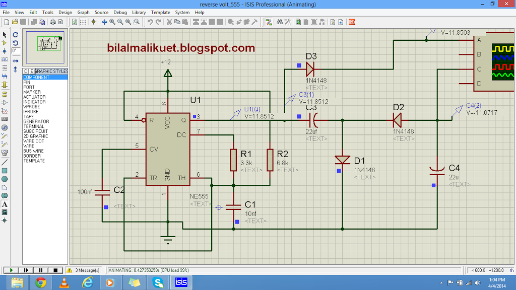
In this tutorial, we will learn how to generate negative voltage using a simple circuit with a 555 timer IC. This circuit can be a cost-effective solution when you need both positive and negative voltages in your project. Check out the circuit diagram and step-by-step instructions, along with practical applications for this technique. If you’re working with audio synthesis, data acquisition systems, or electronic prototyping, this tutorial is for you. Discover the power of negative voltage generation and its diverse applications.
If you are working on a project where you need both positive and negative voltages, you can use the following simple circuit to generate negative voltage instead of making a separate negative voltage supply. This will make your circuit more economical.
Circuit Diagram
To generate a negative 12-volt voltage using a 555 timer IC, you can use the circuit shown in the image you provided. Here are the steps:
- Connect pin 1 (Ground) and pin 5 (Control) of the 555 timer IC to the negative terminal of your power supply or ground.
- Connect pin 8 (VCC) to the positive terminal of your power supply.
- Connect pin 4 (Reset) to pin 8 (VCC) to disable the reset function.
- Connect pins 6 (Threshold) and 2 (Trigger) of the 555 timer IC together.
- Connect a resistor (R1) between pins 6 (Threshold) and 7 (Discharge). This resistor sets the charging rate of the timing capacitor.
- Connect a capacitor (C1) between pin 7 (Discharge) and pin 1 (Ground). This capacitor stores the charge required to generate the negative voltage.
- Connect pin 7 (Discharge) to the negative terminal of your power supply or ground through a diode (D1) to block the positive voltage.
- Connect pin 3 (Output) of the 555 timer IC to the junction of a negative voltage generating circuit, such as a voltage inverter or charge pump.
- Use appropriate components for the negative voltage generating circuit, depending on your specific requirements.

Please note that this circuit is a basic setup for generating a negative voltage, and additional components or modifications may be required depending on the specific application and desired performance.
Let me know if you need any further clarification or assistance.
Video lecture on negative 12 volt
Applications
The negative 12-volt generator circuit using a 555 timer IC can be used in various applications. Here are a few examples:
- Audio and Music Synthesis: Negative voltages are often required in audio and music synthesis circuits. The negative 12-volt generator circuit can be used to power op-amps, filters, and other analog audio components.
- Data Acquisition Systems: Some data acquisition systems, especially those involving analog sensors and signal conditioning, may require negative supply voltages. The negative 12-volt generator circuit can provide the necessary negative voltage for accurate data conversion.
- Electronic Testing and Prototyping: During the testing and prototyping phase of electronic projects, it is common to require both positive and negative supply voltages. The negative 12-volt generator circuit can provide the negative voltage needed for testing purposes.
- Biasing and Amplification: In certain circuit configurations, negative voltages are used for biasing and amplification purposes. The negative 12-volt generator circuit can be used to generate the required negative bias voltage for MOSFETs, operational amplifiers, or other components.
- Signal Conditioning: In various signal conditioning circuits, negative voltages are used to offset and manipulate signals. The negative 12-volt generator circuit can be employed to generate negative reference voltages or bias levels for conditioning analog and digital signals.
Please note that these are just a few examples of the applications for which the negative 12-volt generator circuit using a 555 timer IC can be used. The specific applications can vary depending on the requirements of your project or system.
If you still have any questions, please feel free to leave a comment on this post.
Follow us on facebook
Electrical & electronics engineering news
You may also like to read:
Thks for ur Articles
I love to share my knowledge with others…keep visiting my website for more useful articles.check new articles in recent posts..
Where is the image?Is it my browser problem?
circuit diagram is visible.there is no issue with circuit diagram
if you need complete simluation. comment with your email address
circuit diagram is visible.there is no issue with circuit diagram
can i apply 15v instead of 12v inputs?