Forward Converter Design in Simulink: In last tutorial about simulink we posted a design on dc to dc buck converter using simulink. In this article, we are going to learn how to design dc to dc forward converter with simulink. The forward converter is a dc to dc converter that uses the transformer for step up or step down the dc output voltages. In a simple dc to dc converter, we increase or decrease the dc output voltages by increasing or decreasing the duty ratio of on/off switch, but we can change this duty ratio within certain limits. If we do not care about these limits then our dc to dc converter will not work properly. Here we will say to thanks to transformer which have done easy our life.
Forward converter design in simulink
By using this transformer, we can easily gain the dc output voltages at our requirement means step up or step down the voltages or both can gain simultaneously. This transformer, not only provides the step up or step-down voltages as well as it also provides the galvanic isolation between the load and input side of converter. Here we will design a forward converter in MATLAB Simulink and tell how we make a model as well as how select the circuit components. For designing a forward converter in MATLAB first we will open the MATLAB then click on Simulink library. The Simulink library will be opened with different options shown is figure 1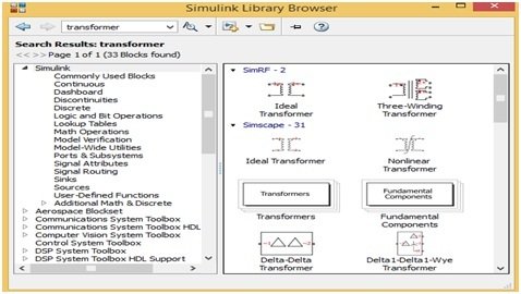
Figure 1 Simulink Library
How to design forward converter in simulink MATLAB?
But first we will make a new model and for this we will click on new model, after that, we will save this model with desired name. Simulink library have different blocks of each components such as transformer, MOSFET, pulse generator and voltmeter shown in figure 1. For searching any block of any component just write the name of component on search Manu bar of Simulink library then different blocks of that required components would be opened then select any one. By doing this, we will make a forward converter design. First, we will write transformer then transformer blocks would be opened shown in figure 1. we will select the linear transformer block which have three winding then we will double click on this block then linear transformer parameter block would be opened shown in figure 2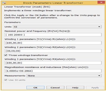
Figure 2 Parameter Block
Components blocks for forward converter in simulink
Here we will make the forward converter in buck mode therefore change in winding turns according to figure 2. Similarly, we will write the power electronics on search Manu bar then power electronic blocks would be opened shown in figure 3,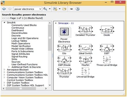
Figure 3 Power Electronics Blocks
Forward converter design with MATLAB simulink circuit diagram
Similarly, we can open all the other blocks such as dc power supply, inductor, capacitor, voltmeter, Ammeter, oscilloscope, pulse generator, display etc. and parameters are set just double clicking on each block. Then, just drag all these blocks on new model in such a way shown in figure 4. Joint all these blocks just by click on each block and then joint with other block shown in figure 4.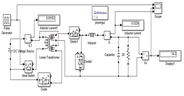
Figure 4 Forward Converter Model
The transfer function this forward converter is defined by the formula
V out = D. Ns/Np V supply (1)
For simulate this model just click on run button which is present at MATLAB Simulink Manu bar
Video simulation results
Forward converter simulation in simulink
We would be simulated this model at 50% duty cycle after setting the supply voltage 100V, transformer turn ratio 30/100, switching frequency 20KH, inductor value 1 mH, capacitor value 100μF and connecting 20Ω resistor as an output load. By using these parameters, the dc output voltage value should be 15 V according to above formula no.1. But the simulated dc output voltage value is 14.2 shown in figure 1 display 1 means it is near to 15. Similarly, we can check this model after running at different duty cycles. The output voltage, inductor current and switching pulse is shown in figure 5
Figure 5 Switch pulse, Inductor and Output Voltages
So this is all about design and analysis of forward converter with simulink. I hope you liked this article and keep visiting our website for more simulink based tutorials and projects.
How do we calculate the values of inductors and capacitor