Introduction to VHDL and introduction to VHDL Data Types: Hi everyone, I hope you are fine and doing well. Today we are going to start a getting started tutorial on VHDL and VHDL data types. There will be a series of tutorials on VHDL and its data types. I will also add more VHDL tutorials in this article. so it will be series of VHDL tutorials. Starting from VHDL programming and VHDL based projects/ By reading this article, you will be able to read and understand the design of VHDL and then you can create your own VHDL Designs. You will also be able to do programming of FPGA 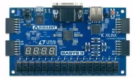 development board.
Introduction to VHDL
First of all we will discuss, specifications of VHDL Language. There will be complete detail of VHDL Data Types, Coding Structure, styles and tools of Xilinx and ALTERA which are main players of FPGA. Then we will go through the set of seven labs. These labs vary from simple errors to more complex or RC Servo controllers. There will be complete detail of implementation of a UART on FPGA then you will have a full functional UART and will be be able to make commands on your computer to make some specific things happen on FPGA. There will be implementation of Communication Pro on FPGA. Among these protocols is an infrared receiver, which reads infrared rays coming from a standard TV remote and we will implement them and understand what’s going on. Then we will study Advance LED Control course. You will get to know from where brightness comes in LED, how it changes color.
Getting started with VHDL programming
You might have questions in your mind what is VHDL and what it is used for? Here we are going into its explanation. VHDL stands for “VHSIC High Descriptive Language” and VHSIC stands for “Very High Speed Integrated Circuit”. What VHDL used for is to describe actual physical circuit. In VHDL we are describing a circuit using codes.

History of VHDL
VHDL was developed in 1981 by the Department of Defense, Unite States of America. The basic purpose of development of VHDL was to address hardware life cycle crisis of electronic systems. You can put FPGA or CPLD on circuit board and you can change electronic systems by programming. All rights of the language were given to the IEEE (Institute of Electrical and Electronics Engineers) by DoD (Department of Defense). VHDL has defined language and standards.
Here we have list of devices that use VHDL Data types.
- FPGA: It is
- Field
- Programmable
- Gate
- Array
- CPLD: It is
- Complex
- Programmable
- Logic
- Device
- ASIC: It is
- Application
- Specific
- Integrated
- Circuit
CPLD is smaller and less capable than FPGA. FPGA is more powerful than CPLD. Chip, processor and microprocessors are ASIC. ASIC is a chip that is function able. It has specific designated function. You can used VHDL like how you want the circuit inside ASIC to work.
Comparison of FPGA and CPLD
FPGA
FPGA is deigned in such a way that it uses logic blocks.
It has much higher logic capacity as compared to CPLD.
Typically FPGA is used for complex designs.
It has volatile memory. FPGA loses its configuration when it is powered off. So, every time you turn on FPGA, it has to read its configuration files
FPGA is more powerful so it is more expensive than CPLD.
CPLD
CPLD has less logic capacity than FPGA.
It is used for simpler less complex designs.
It has non-volatile memory. If your CPLD off and then turn power own, CPLD retains its configuration.
You use CPLD for very simpler designs so it is cost effective as compared to FPGA. If you have to add some complexity in design, you have to move to FPGA as it is more powerful.
The major manufacturers of FPGA and CPLD are Xilinx and ALTERA.
Key Points of VHDL
- VHDL is not a programming language. We are not programming FPGA we are writing configuration file or we are describing how in actual a physical digital circuit runs on FPGA.
- VHDL is not a software in actual. It is basically used to describe hardware that software runs on.
- When VHDL is synthesized, the compiler through codes runs and builds gates specified in VHDL code and implements them on targeted logic device.
- Top 2 manufacturers of FPGA and CPLD are Altera and Xilinx.
Variables, Signals, Constants and Files used in VHDL Design
Data Classes
VHDL has different data types just like other programming languages. Further, there is data class. Each data type in VHDL is specified by data class. There are 4 different data classes
- Signals
- Constants
- Files
- Variables
Signals
Signal is an object with current value and projected values. The projected values can be changed as many times as possible. This is most common class used in design. You use signals to construct internal bus, shift registers, RAM. You use digital circuits to create signals.
Variables
An object with only a current value. Variable values can be changes as many times as desired. Variables go away after synthesis. Variables are used inside a process to perform actions sequentially. The most common variables used in VHDL are used in construction of Gates, Components and other pieces of digital hardware.
We mostly use signals in designs. These variables help to construct signals.
Constants
These are objects who values cannot be changed after it is initially specifies. We use variables when we have variety of designs but in constants we have specific design. For instance if we have given value to clock speed as 50, we cannot change it once we have specified it.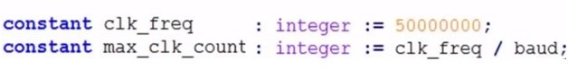
Whereas, baud is another constant already defined. You can only change clk frequency, other values, max clk count, baud all are constants. So, constants are very useful in VHDL Designs.
Files
Files is an object that consists of a sequence of values. These are only used in test benches. We have .txt files and .csv files. In design we don’t actually use files, you may use if you want to initialize memory values inside designs. Most commonly files class is only for test benches. For stimulation, you can give values in form of files, take these values and apply to stimulus.
Signed and Unsigned Data Types in VHDL
Unsigned Data Type
An unsigned data type is declared in a package NUMERIC _ STD.
An unsigned data type is array of std _ logic. Std _ logic is between 1 and 0. Type signed is interpreted as std_logic_vector but has different operators that are available. It can only represent positive numbers. We can’t go for a negative number. In any unsigned data type, the left most bit is MSb (Most Significant Bit)Let’s have a look to data type example. We have a data class which is signal and then we have signal name which is count then we have semi colon and data type which is unsigned denoted in VHDL and then the size of data type which in this case in -1 down to 0. If we have 8 bits, then size will be 8-1=7 down to 0. After that we have semi colon equals to gives initial value. Others implies we have initial value set to 0.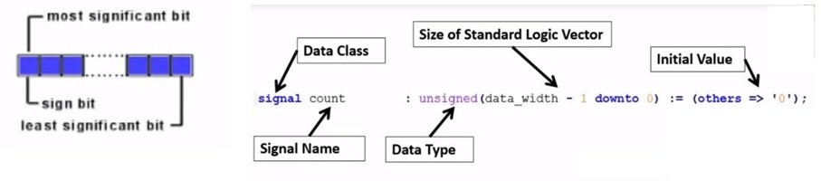
Signed Data Types
Let’s have a look to signed data types. It is also declared in package NUMERIC _ STD. Signed Data Type is also array of std _ logic just like unsinged data type. However, the difference between both the data types is that signed data type can represent negative as well as positive number. The values are represented in component form. You can store your values in files. The left most is the Msb.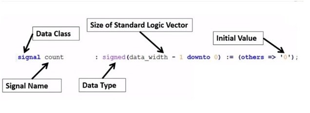
Here we have an example of signed data type. We have a data class which is signal and then we have signal name which is count then we have semi colon and data type which is signed denoted in VHDL and then the size of data type which in this case in -1 down to 0 i.e. how many bits in signed data type. In this case we are saying data_width – 1 downto 0. If we have data width of 8 bit then it will be 8-1 i.e. 7 downto 0. Then we have initial values and we are specifying them all to be 0.
Standard Logic Vectors/ Standard Logic Data Types
A standard logic data type is defined in package STD_LOGIC_1164. We can say a ”STD_LOGIC” may be logic “1” or logic “0”. The basis of this level is on the voltage level of that voltage which is supplied to the FPGA. Inside FPGA the voltage supplied 3.3 would be 1 and 0 would be 0.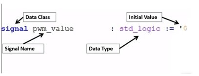
A standard logic data type is actually a single binary bit. It is denoted by “std_logic”. Let’s have a look to standard logic data type example. Standard logic data type values are commonly used as indicators or flags. It will tell you a yes or a no. You should go or not. It indicates a delay has been reaches or a button has been pushed so on and so far. Say for instance, you have a data class which is a signal and signal name is pwm_value. Data Type is specifying a std_logic and giving an initial value 0. If you are going to put two 1 or to 0, it will be invalid.
A Standard Logic Vector Data Type is also defined in package STD_LOGIC_1164. A std_logic_vector is a set of multiple standard logic values. A std_logic_vector is a vector of standard logics. A std_logic_vector can be combination of ‘1’s and ‘0’s.
Standard Logic Value Example
Standard logic vector data types are commonly used to hold addresses, data, led 7 segment display data, etc. This is very commonly used data type in VHDL and the main advantage is that you can in with your individual target bits. A simple example, for example an array of LED’s, you can create a standard logic vector to a width. If you have 15 LED’s, you can make 15 bits wide and you can in with each target pair, you can turn your LED on or turn your LED off.
So, if we have an example of standard logic vector, we have a data class which is a signal. We have signal name seg_out and our data type std_logic_vector and then we specify data type size and in this case we are specifying 7 bits wide i.e. 6 down to 0 that gives us 2 of 7 bits. Then the initial value is the actual value of this bit. In this case we have 101000 and the initial value can be any combination of 1 and 0 we want to go for.
Integer and Boolean Data Types in VHDL
We will be discussing Integers and Boolean Data Types in VHDL.
Integer
Integer is declared in package STANDARD. It has values that are whole numbers in specified range. We can represent only whole numbers and no decimal numbers. Say for instance, we can represent 3 and 4 but not any number in between 3 and 4 like 3.2.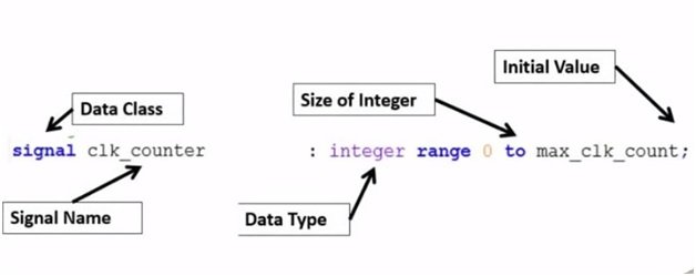
Integer allows you to use basic mathematical operations like ‘+’ and ‘-‘. If we have two integers, we can add them together. This is the main benefit of Integers over standard logic vectors. However, there is drawback that you cannot modify individually any specific bit. We can specify range in which we can change that number but we cannot individually change the specific bit. An integer is denoted by its spellings ‘integer’.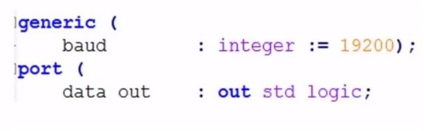
Example of Integer
We have a data class which is a signal and our signal name is clk_counter. Then we have a data type, integer which is specified by its spellings. We have size of integer in which we specify size of integer, we give it a range from low end to high end. In this case, we gave range from 0 to max_clk_count. Whatever, the value of max_clk_count is that is the size of our integer. If the max_clk_count is 4, then our range will be from 0 to 4 and integer can be any whole number between, 0, 1, 2, 3 and 4, you initialize your integer.
We can also use integers in generic which is commonly used. In generic we have baud and we give integer a value 19200, then you give integer a specific range depending on which compiler or synthesizer you are using. The most commonly used is 32 bit and you give range from 0 to 65000 or a very large whole number.
Boolean
Next data type we are going to talk about is Boolean. Boolean is also declared in package STANDARD. It can either 1 or 0, true or false. 1 is equal to true and 0 is equal to false. It is denoted by keyword ‘Boolean’.
Example of Boolean
It is most commonly used in generic which has a name synch_reset. The data type is specified at Boolean and then we have Boolean value which in this case is true and true means 1 and if the Boolean value is false it means it is 0.Till now, we have discussed all the data types used in VHDL. Let’s move towards syntax.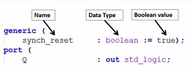
Initializing the Values
There are some initial values in VHDL. Here we have few examples which we can work out to show you how it’s done.
— is a comment in VHDL. You type — and then your text.
Then you write your data class which is signal and class name can be any signed, unsigned, integer, Boolean etc.
- If you want to open new file, go to files, and then new.

- Go to language and change your language to VHDL.

- After that type your data class, signal.

- To signal A, we have given initial value of 4 which comes in data type integer.


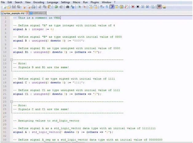
If we talk about signal B, the data type is unsigned and the initial value is 0000. For both signed and unsigned we have bit values. This is an unsigned data types of 4 bits from 3 down to 0.In B1, we have initialized value with others = 0 instead of writing four 0s. The bit size in both B and B1 is same.If it is of 24bits, 32bits or even bigger 64bits, instead of writing so many 0s we can write others = 0. Signal B and B1 are same only the way of initializing is different.
In the same way if you see signal C and C1 with data type unsigned, they both are same only the difference is in initializing. In signal C we have bit size of 4 and our initial value is 1. We wrote initial value 1111. But in C1 again our bit size is 4 but we initialized it as others = 1. The benefit of C1 over C is that we don’t have to write so many 1s, if our bit size is bigger.
Now let’s see how to write syntax of std_logic_vector.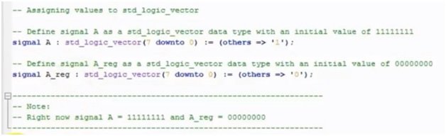
Write data class which is signal, then data class name which is A and then colon and data type which is std_logic_vector, then write bit size (7 down to 0) i.e. 8 bits. Then colon equal to initial value which is others implies 1.Signal A and A_reg have same bit size but different initial values. For A, initial value is 11111111 i.e. eight 1s and for A_reg, initial value is 00000000 i.e. eight 0s.
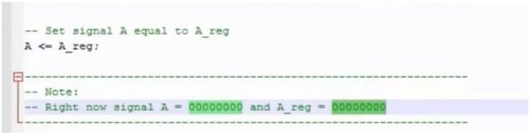
In VHDL, we can give same value to two data types. For instance, if you want your signal A equals to signal A_req, write the syntax as shown in picture above i.e. A <= A_req; this will make your signal A equal to signal A_req i.e. A = 00000000 and A_req = 00000000.
Data Types Examples in VHDL Designs
In Picture below, on the top is Behavioral Full Adder. The two — and the text after it indicate that it is a comment. Then its library IEEE in the 2nd line and then use IEEE.STD_LOGIC_1164.All; It tells us that data type standard logic and standard logic vector both are used. Then we have an entity which is called Full_Adder_2. Different keywords in VHDL can be highlighted in different colors. Then we have s and c_out which a standard data type which means it has either 1 or 0 for a single bit. Then we have simple x, y and c_in which is a one data standard logic.
Then at line 16 and 17, we have signals, they are inputs and outputs and are standard logic vectors. In input we have 2 down to 0 which gives 3 bits and in output we have 1 downto 0 which gives us 2 bits. We have three inputs x, y and c_in and two outputs s and c_out. Then we have keyword begin which has another comment — combine inputs & outputs into std_logic_vector. The two dashes and the green color indicates that it is a comment. Then we have inputs with an arrow and equality sign and the inputs taken are c_in, x and y which is 3 standard logic vectors i.e. 2 downto 0. Then we have output c_out with its value 1 and s output with its value 0.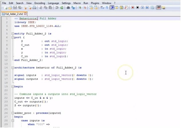
Then we have a process named adder_proc. We have a process keyword, inputs. Then there are essential checks of inputs with the outputs. The commands in begin tell us from where our process begins. We have a case keyword and then ‘when’ which is a case signal. We are checking case inputs against any of these when values. Then, if none of the when statement matches, it will go to others. Then we have end case keyword, then end process and end behavior.This was the syntax of VHDL.
Here we have an example. This is a post width massachusetts design in VHDL.
The purpose of this example is to show difference between different data types. First data type we have is integer which is in generic section. We have bit depth which is an integer value and initializing it to value 8. In line below that i.e. line # 13, we have input_clk which is also an integer and initializing value is 50000000 which represents 50MHz clk. Then we have freq and we are initializing it to 50. We use generics to represent different values which come in port section. In 17 line, in resolution keyword, we have used bit depth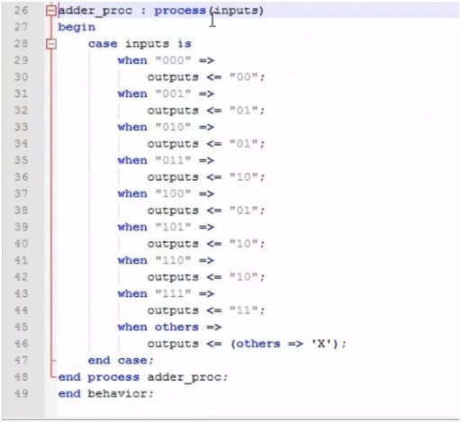
We are also using constants. In 26 line, we have constant max_freq_count with integer value input_clk / freq. You can also see, we have signals that are placed in Architecture section.