HM-10 Bluetooth Module is the cheapest Bluetooth with 4.0 technology. The module comes in multiple communication methods but the only thing that makes it different from others is its latest technology at the cheapest rates. The use of Bluetooth with 4.0 technology has been increasing recently due to its fast speed and much less power consumption. There are a bunch of Bluetooth technologies with 2.0 and 3.0 technology but HM-10 is the one with 4.0 technology. It only can send the data up to 100 meters with a 24Mbs rate, which is much faster for other modules. The 3.0 can only achieve the speed up to 3Mbs speed.
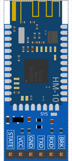
Pinout diagram HM-10
HM-10 Bluetooth module has a single communication method known as serial communication. To use it the device always depends on a third-party device. All those pins are:
Pin Configuration Details
VCC
To power input of the module, the VCC pin connects to the positive terminal of the power.
GND
The ground pin is always important for every DC circuit to make the common ground with power and other devices for proper function. GND pin will help to fulfill the requirement.
RX
HC10 communicates follows the UART communication protocol for data sending and receiving. RX will help to receiver the data from Arduino/microcontroller.
TX
TX will send the data from the Bluetooth to the Arduino/microcontroller.
State
This pin is just for state representation. There will a HIGH output signal at state pin for established Bluetooth connection otherwise it will be at a low.
BRK
BRK represents the break, which helps to disconnect the connection of Bluetooth with another module. To disconnect the connect apply the LOW input signal on it.
Button
There is a button on the device to break the connection just like a BRK pin.
LED
The onboard led is for visualization. This helps to understand the current situation of the Bluetooth device.
HM-10 BT Module Features
- HM-10 has the latest 4.0 Bluetooth technology.
- There is no limit in sending bytes with HM-10.
- Power consumption is much less even in an operating state with this module.
- The HC10 module uses the 2.5GHz frequency band at the range of 100meter in an open area.
- It is useable as a Master or Slave just by disconnecting the connections.
- The module operates at 2-3.7V only which is common in every TTL/CMOS device.
- A single module has its 256Kb flash memory and 8Kb SRAM.
- There are onboard GPIO pins within the module which are usable through UART communications,
- The GFSK (Gaussian Frequency Shift Keying) helps to transfer the data for the module.
- The device offers data and command mode which helps to set the internal setting according to the project requirement.
HM-10 Bluetooth Module Applications
- Every commercial device like headphones and mice are now using HM-10 because of its low power consumption.
- Most of the laptops also have 4.0 Bluetooth.
- In IoT continuous data sending devices also have HM-10 because of its no limit feature.
- Every two ways communication device like robots, remote control cars uses the HM-10 at developing level.
How To use HM-10
The use of HM-10 is much easier just like other modules. The module is useable directly with serial communication but it sometimes faces the issue during communication. It’s better to use the libraries with digital pins to avoid problems. by using external libraries, the programming may become complex for some developers. The module HM-10 mostly helps with Arduino because there’s a lot of work done on the module with this board. To use the HM-10 the following library is helping to communicate.
#include <AltSoftSerial.h>
During using the HM-10 the board may sometimes need to use the serial communication which can affect the Bluetooth. To avoid any kind of interruption digital pins can communicate with the Bluetooth with the use of this library. The device can act both slave and master but both modes have some instructions to operate.
HM-10 Bluetooth Module interfacing with Arduino nano
To use the Digital pins of the Arduino with HM-10 the following connection needs to establish.

The library has some requirements by default which should follow by every serial communication module. It allows only specific pins to operate as a serial.
Serial Pins of different development Boards
For different boards they are:
| Board | Transmit | Receive | PWM useable |
|---|---|---|---|
| Arduino Uno/Nano. | 9 | 8 | 10 |
| Arduino Leonardo. | 5 | 13 | none |
| Arduino Mega. | 46 | 48 | 44, 45 |
| Teensy 3.0 & 3.1. | 21 | 22 | 22 |
| Teensy 2.0. | 9 | 10 | none |
| Teensy++ 2.0. | 25 | 4 | 26, 27 |
| Sanguino. | 13 | 14 | 12 |
| Wiring-S. | 5 | 6 | 12 |
HM-10 Bluetooth Module as a Slave/Master
The device will act as a Slave/Master in default mode. To use the module as a slave the following code will help.
#include <AltSoftSerial.h>

AltSoftSerial bluetoothSerial;

boolean NL = true;

void setup() {

Serial.begin(9600);

while (!Serial) ;

bluetoothSerial.begin(9600);

}


void loop() {

char Serialdata;


if (Serial.available()) {

Serialdata = Serial.read();

bluetoothSerial.print(Serialdata);


if (Serialdata!=10 & Serialdata!=13 )

{

bluetoothSerial.write(Serialdata);

}

if (NL) { Serial.print("\r\n>"); NL = false; }

Serial.write(Serialdata);

if (Serialdata==10) { NL = true; }

}

if (bluetoothSerial.available()) {

Serialdata = bluetoothSerial.read();

Serial.print(Serialdata);

}

}
The code is for communication between Arduino and Bluetooth. The code will help to communicate with Bluetooth whenever it is busy. By this method, the data mode and command mode is accessible by using the same code.
HM-10 Command and Data Mode
The device will act as a data and command mode but it will need to follow some procedure to go into its command mode. In command mode, the device is changeable from slave to master. First open the Arduino com port then break the connection between the HC10 and another Bluetooth device, which can be done by three methods.
- Button on the board
- By applying High input at BRK pin
- By restarting the device.
After connection break, the device will connect again and it is identifiable from com port. Now enter the command:
AT
Then an “ok” message will appear which will verify the connection.
AT Commands
Now following commands are usable for different functions.
| COMMANDS | DETAIL |
|---|---|
| AT | To enter in the command mode |
| AT+NAME? | Returns the current module name |
| AT+NAMEnewname | To change the name of the module us this command |
| AT+ADDR? | It returns the MAC address of the module HM-10 |
| AT+VERS?
AT+VERR? | It returns the version of the module |
| AT+RESET | Rest will help to restart the connection |
| AT+RENEW | To reset all the setting by one command |
| AT+BAUD? | To get the info about the setting of baud rates |
| AT+BAUDx | It will help to set the new value for the baud rate |
| AT+NOTI | To view the notification status |
| AT+NOT0, AT+NOT1 | It helps to turn on and off the notifications. |
| AT+NOTI? | Helps to view the notification status in 0 and 1 form |
| AT+PASS? | For query of the password in pairing |
| AT+PASS | To set new Password |
| AT+ROLE? | To check the Modes of the module |
| AT+ROLEx | To change the modes by replacing X with 0 for slave and 1 for master |
| AT+IMME? | The connection establishes methods are viewable in the serial monitor |
| AT+IMMEx | Change the X with for auto-connect and 1 with the manual. |
| AT+RESET | It will restart the HM-10 |
| AT+RENEW | Reset with factory settings |
Security issue
Security is not a major issue in the module. It can only communicate with a single device. the module keeps sending data and gets confirmation from the other end. In case of loss in connection, the device gets disconnects and stops the transmission of data. The device uses the password to pair up with other devices too. It has two communication methods, Auto and manual. The manual method helps to avoid the connection with any unknown device which makes it more secure.
HM-10 Bluetooth Module Example
In this example, the device will be used for controlling an LED. In Arduino, the onboard LEDs are usable too. First, connects the circuit according to the following diagram.

Now to send the data to the Bluetooth device any predesigned mobile app is usable There is a bunch of apps that are usable but to use the third-party apps first read their instructions. Those apps always have special instructions for each button. Then set instruction which the below Arduino code.
#include <AltSoftSerial.h>

AltSoftSerial bluetoothSerial;


boolean NL = true;

void setup() {

Serial.begin(9600);

while (!Serial) ;

bluetoothSerial.begin(9600);

pinMode(13, OUTPUT);

}


void loop() {

char Serialdata;


if (Serial.available()) {

Serialdata = Serial.read();

bluetoothSerial.print(Serialdata);


if (Serialdata!=10 & Serialdata!=13 )

{

bluetoothSerial.write(Serialdata);

}

if (NL) { Serial.print("\r\n>"); NL = false; }

Serial.write(Serialdata);

if (Serialdata==10) { NL = true; }


}

if (bluetoothSerial.available()) {

Serialdata = bluetoothSerial.read();

if(Serialdata == 1) digitalWrite(13, HIGH); // Change the 1 according to the mobile app instructions

else digitalWrite(13, LOW);


Serial.print(Serialdata);

}

}
The is just performing a basic operation and making the LED output HIGH whenever the incoming signal from the Bluetooth is one.
Other Bluetooth Tutorials and Projects:
- Bluetooth module HC 05 interfacing with pic microcontroller
- HC06 Bluetooth Module Guide with Arduino Interfacing
Alternative Modules:
JUNK!
In file included from /home/gary/Arduino/libraries/AltSoftSerial/AltSoftSerial.cpp:35:
/home/gary/Arduino/libraries/AltSoftSerial/config/AltSoftSerial_Boards.h:136:2: error: #error “Please define your board timer and pins”
#error “Please define your board timer and pins”
^~~~~
exit status 1
Error compiling for board CubeCell-Board(HTCC-AB01).