HX711 is a 24-bit analog to digital converter (ADC) IC. It as built-in a preamplifier that is used to amplify low voltage signals. HX711 chip takes voltage signals as an input and provides digital values. The preamplifier handles low voltages. It has an on-chip power supply regulator that provides analog power due to which you don’t need an external supply regulator. You can directly interface with a bridge sensor. This chip has two analog channels such as A and B. We can program channel ‘A’ gain either 128 or 64. On the other hand, channel B has constant gain of 32.
Preamplifier Function
This chip is mainly suitable for weight measurement applications. The load cells that are used in weight scaling applications give very low output voltage. This output voltage is usually in the order of millivolts. Conventional, ADC ICs such as ADC0804 can not measure such low voltage with good resolution or accuracy. HX711 ADC can measure these low scale voltages and convert them into digital values. Because it has a preamplifier inside the chip which makes it suitable for such applications.
HX711 Pin Configuration
Pinout diagram shows the pin assignment of each pin. This ADC has 16 pins. As you can depict from pinout that it has two ADC channels and each channel converts an analog signal into a 28-bit long digital value.
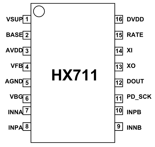
Pin#01: VSUP
It is the regulated power supply pin whose range lies in between 2.7 V to 5.5 V.
Pin#02: BASE
It is the regulator control output.
Pin#03: AVDD
The Power analog supply is applied at this pin and its value should lie in between 2.6 V and 5.5V.
Pin#04: VFB
It is the analog control input of a regulator which is connected to analogue ground when not used.
Pin#05: AGND
Analog Ground
Pin#06: VBG
Analog reference bypass output
Pin#07: INA-
Negative analog Input of Channel A
Pin#08: INA+
Positive analog input of Channel A
Pin#09: INB-
Negative analog input of Channel B
Pin#10: INB+
Positive analog input of channel B
Pin#11: PD_SCK
Serial digital clock input
Pin#12: DOUT
Serial Digital Output
Pin#13: XO
Digital Crystal I/O
Pin#14: XI
Digital Crystal I/O or external clock input
Pin#15: RATE
Digital input pin. It controls data rate at output. When this pin is low, data rate is 10Hz. When it is high, data rate is 80Hz.
Pin#16: DVDD
It is the digital power supply whose value lies between 2.6V to 5.5V.
Features
- It is an ADC converter with two differential input channels
- An active-low noise PGA is integrated inside the chip which provides the gain of 32, 64 and 128
- It has a power-on-reset capability which simplifies digital interface initialization.
- All controls to the IC are made through the pins. Programming is not needed.
- You can select a data rate of 10SPS or 80SPS at the output.
- Provides simultaneous supply rejection of 50Hz and 60Hz supply.
- Built-in analog power supply regulator
- The voltage supply range is from 2.6V to 5.5V
- The temperature range is from -40 °C to +85℃
Where to use HX711?
HX711 has a power supply regulator due to which you can use it for load-cell and ADC analog power supply. It has an in-built oscillator along with optional external crystal. Therefore, you don’t need external components. The load cells provide outputs in millivolts which are difficult to handle. You can use it with microcontrollers.
How to use ADC?
It has two differential input channels A and B which are selecttable by the input multiplexer and apply this channel input to the PGA.
Chip Activation
- To activate the on-chip oscillator, connect pin14 to ground. The output data rate is 10SPS or 80SPS. Use a crystal across XI and XO pins to obtain an accurate data rate at the output.
- Pin11 and pin12 are used to retrieve data. The pin12 becomes HIGH, when data is not ready. At that time, the pin11 input should below. When pin12 is low, it means data is ready to be retrieved. Data comes out from the pin 12 on applying 25 to 27 positive clock signals.

Clock Pulses and Control Inputs
- The number of the input clock pulses control inputs and select gain. Their number should not be less than 25 or greater than 27. Otherwise, it will cause serial communication error.
- It has a power-on reset ability which will reset the IC on powering up a chip.
- During normal operation, pin11 clock input is low.
- When a positive edge transition is applied at pin 11 and stays in the same logic for longer than 60µs, the IC enters power-down mode.
Reset Operation
- The chip will reset and reenters into the normal mode of operation when pin 11 returns to low. After this input channel will be set to Channel A by default.
Weigh scale Application Example Circuit
Now let’s understand the interfacing of hx711 with any microcontroller and a load cell.
In this circuit, we connect a load cell output terminals with channel A inverting and non-inverting pins. Because we can directly interface bridge sensors ( having differential inputs) with this analog channel.
Note: Do not connect the bridge sensor directly with channel B.
Also, you can observe from the circuit diagram that we power the load cell from the HX711 chip. Therefore, this ADC chip eliminates the need for external power regulator. Consequently, it will make your design cost-effective.
Working Principle
Working Principle of the circuit is very simple.
- When we apply weigh on the load cell, it produces an analog voltage at the output pins according to the magnitude of the load.
- Channel A reads sensors output through a programmable gain amplifier and input mux.
- Gain amplifier adjusts the magnitude of the input signal and passed this signal to the digital conversion interface circuit.
- The digital interface circuit converts the analog input signal into a 26-bit digital signal and sends signals to DOUT output pin.

- After that, we can use any microcontroller such as Arduino, PIC16F877A which has GPIO pins to read data from DOUT pin,
- We can easily read data from the I2C port using any microcontroller.

You can check these I2C communication tutorials:
HX711 Applications
- Automatic Doors
- Weigh Scales
- Industrial Process Control
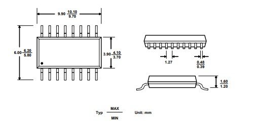
2D Diagram
The digital interface is _NOT_ I2C. It’s just a simple shift register — strobe the CLK pin high and ~100 ns later the new data bit shifts out.
Please fix your article.
Hi,
Thanks for pointing out a mistake, We will fix it.
November 29, 2021. The article still erroneously shows the clock / data as I2C.
One could certainly write some code to make a small microcontroller such as from the PIC16Fxxx or PIC18Fxxx family into an I2C slave, then use other GPIO pins to communicate with one or more HX711 chips.
But the HX711 interface is similar to but not fully SPI either. In my application since the I2C port on the uC is already set up as a slave to deliver the results of multiple sensors, I’m going to just bit-bang a pair of spare I/O pins to read the HX711s and attached load cells.