Recommended Components
The following parts are used in this article, along with a generic electronics kit that is handy for building and testing the circuit.
| Component | How it’s used | Buy on Amazon |
|---|---|---|
| LM339 quad comparator | The LM339 quad differential comparator IC this article covers. | Check Price |
| Electronic component assortment kit (1390 pcs) | A handy assortment of resistors, capacitors, LEDs, diodes and transistors for building circuits. | Check Price |
| Digital multimeter (AstroAI) | Measures voltage, current, resistance and checks continuity while you build and debug. | Check Price |
| Breadboard | Solderless base for prototyping the circuit. | Check Price |
| Jumper Wires | Make the connections on the breadboard. | Check Price |
As an Amazon Associate we earn from qualifying purchases. Prices and availability are accurate as of the date/time indicated and are subject to change.
LM339 Pinout
This quad differential comparator IC has fourteen pins. Out of these, three pins are assigned to each comparator. To make a difference, we give different colors to the pins of each comparator. But a common power supply pins use for all comparators.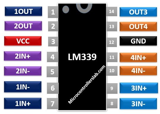 Pin DescriptionAll the four comparators consist of two input pins and one output pin and a shared positive supply rail and ground.
- Pins4, 6, 8, 10 are the negative inputs
- Pins5, 7, 9, 11 are the positive inputs
- Pins1, 2, 13, 14 are the output pins.
- Pin3 and 12 are power supply pins.
LM339 Working Principle
The working of this differential comparator IC is similar to other comparators. Each COM has three pins. Input pins are inverting (-IN) and non-inverting (+IN). We connect positive input voltage to the non-inverting terminal and a negative input signal to the inverting pin.- If the voltage at the -IN pin is greater than the +IN and offset voltage pins, the output will be logic zero.
- Similarly, if the voltage at the +IN pin is higher than -IN and offset terminals, the logic high signal will appear at the output pin.
Features
Some of the major features of the LM339 IC are:- Four comparators have very low noise interference among them.
- Operate from the single power supply as well as dual power supply over a wide voltage range.
- For single-supply operation, the voltage supply value should lie in between +3.0 V to +36 V. In case of dual supply, the range is +18V and -18V.
- It has low input biasing current, offset current and offset voltage.
- This device is compatible with TTL, MOS, and CMOS logic forms.
- It provides a low supply current drain of typically 0.8mA. Its value is independent of voltage supply.
- The common-mode input voltage range within which the IC performs its operation normally includes ground even if regulated from a single power supply voltage.
- The output saturation voltage is typically 130mV at 4mA.
Where to use LM339?
LM339 IC is a high precision comparator designed to perform its operation using only a single power supply, but you can also use dual power supply if the two requirements are satisfied. Firstly, two power supplies have a difference of 2 V to 36 V between them. And the second one is pin3 should be at least 1.5 V more positive than the input common-mode voltage.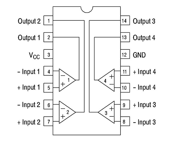 Basically, it gives the digital signal at the output terminal by comparing the two input signals. The output signal determines which input is greater. In the same way, this IC can function as a level detector. This device has a distinct feature of low power drain which makes it well suited for battery operation. In addition to the above-mentioned features, it is handy to use, less expensive and provides good performance.
How to use LM339?
The working principle of this IC is simple. If the inverting pin voltage is greater than the input voltage signal applied at the non-inverting pin, the output will generate a high signal otherwise a low signal.Zero Crossed Detector Circuit Example
The figure below shows a simple zero cross detector circuit to demonstrate the operation of the LM339 chip. Apply AC signal at the input. Apply zero voltage or connect non-inverting terminal to ground. LM339 IC compares the values of two inputs against each other.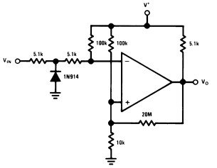 When the AC signal crosses the zero-reference voltage, the output of comparator changes. The diode protects the chip from damage when the input voltage goes below the range specified for common-mode input voltage. The LM339 chip possesses an open collector of a transistor at output pin therefore, we have connected a resistor of 5.1 kΩ as a pull-up resistor.
Equivalent Voltage Comparators
LM139, LM239, LM2901, LM311Applications
It includes:- Square wave pulse generation and time delay generation
- Analog to digital conversion of signals
- Voltage Controlled Oscillators
- Peak detectors and in level detection applications
- Measuring instruments
- Transducer Amplifiers
2D Diagram
The dimensions for the 14 pin PDIP package are given in the diagram below.
Please can you give me a cct for converting sine/cos inputs to TTL o/p for encoder . Quad square wave.
Using LM339 or LM393
Thankyou
There is a error on the pretty graphic, pin 4 and 5 are reversed!