Nokia5110 LCD screen is a simple black and white screen but it was the best display for mobile in its time. The usage of the screen was mostly in the Nokia 3310 and 5110. Therefore, the increase of color graphics and smart screens the screen is now the only available in most of the developing projects and small low budget devices. In the LCD, the Liquid crystal method helps to show the output data with a total of 84×48 pixels. The LCD uses the SPI pins to communicate. It is useable with Arduino officially with the use of the library. The display colors also come in multiple backlights.
What is Nokia5510 LCD Display?
Nokia 5510 LCD display is a graphics screen LCD display and has been used for a lot of applications. Initially, it was designed only for iconic Nokia 5510 cell phone screen but now we can easily use it for different purposes such as for displaying alphanumeric character, draw lines, shapes and even for displaying bitmap images because of its 84*48 monochrome pixels mean 84 columns and 48 rows. All necessary functions of this display are packed in a single small chip which is operated at very low voltages. It is very low cost more precise, more reliable and easy to use LCD display.
Nokia5110 Pinout Diagram
The pin configuration of the LCD is almost SPI but in oneway only. The LCD only uses a one-way communication to operate because it doesn’t have to send any data to the microcontroller. However, it has two modes of data and command modes for operating properly.
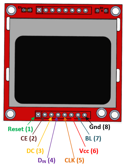
Nokia5510 Pinout Diagram Details
| PINS | DETAIL | |
|---|---|---|
| Pin6 | Power (VCC) | The power pin will power up the LCD with external voltage to activate it. |
| Pin7 | Back Light (BL) | The backlight is the internal color of the LCD. It is just turn on by giving the power input to its pin. |
| Pin8 | Ground (GND) | The ground is internally common with LED and whole LCD. It helps to make common ground with external power and devices. |
SPI Communication Pins
| PINS | DETAIL | |
|---|---|---|
| Pin1 | Reset | The reset pins are to reset the Nokia5110 display. Here it will help in the programming library to reset it. |
| Pin2 | Chip Enable (CE) | The enable pin in SPI helps to select the device in case of multiple devices. Here it will active the LCD with the LOW input signal. |
| Pin3 | Data/Command (DC) | Pin3 helps to switch between the command/data mode. The HIGH signal is for data and LOW signal for command. |
| Pin4 | Serial IN (DIN) | The “serial in” pin will send the data from the microcontroller/Arduino to the LCD Nokia5110. |
| Pin5 | Clock (CLK) | The LCD and microcontroller will require a common clock to operate because of their SPI communication. CLK pin will help to make it. |
How to make connections with Microcontroller?
Every Nokia 5510 LCD display consists of eight pins which are used for different purposes. Its first one pin is reset pin and used for resetting the LCD display. during reset zero voltages are applied at this pin. Second one is CE pin, which is enable pin and is used for displaying any particular display when more then one SPI peripherals are in used. Third one is DC pin, which data/command pin and is used for switching data mode (high) to command mode (low).
Forth one is DIN pin, which serial input pin and is used for serial communication means for sending serial instruction or data. Fifth one is CLK pin, which is clock pin and is used for suppling clock source because all SPI modules are required a common clock. Sixth one VCC pin, which is voltage supplying pin and is used for turning on or off the LCD display. For power on this LCD display 2.7 volts to 3.3 volts dc voltages are applied at VCC pin. Seventh one is BL pin, which is back light pin and used for power on the back light of this LCD display. Similarly, the last one is GND pin, which is ground pin and is used for supplying ground voltages to this LCD display.
Nokia5110 Features
- The LCD is of 84×48 pixels combination, which are useable with any microcontroller.
- The SPI communication helps to communicate with LCD, which is common in every microcontroller.
- It is available in multiple backlights.
- The PCD8544 LCD driver helps to drive it, which is already present on it.
- Bitmaps images are viewable on the Nokia5110.
Nokia5110 LCD Applications
- Most of the pocket games use the LCD, like snake games, etc.
- Mobile phones have a wide use of LCD.
- The LCD is still in most of the industrial and commercial applications.
Nokia5110 LCD Constructions
The Nokia5110 LCD uses a simple liquid crystal method for each pixel to show the data. In the liquid crystal, the three layers help to make a single pixel. The first layer is the glass, second is the polarized sheet and the third one is the crystal molecules. The light passes from one glass towards the other glass but it has to move from two polarized sheets. The polarized sheets are at different angles. So, to pass the light the molecules need to change their positions so the light gets a change in angle according to the second sheet with the help of modules. If light passes from it, then it is viewable by the user but in case of deflection, the LCD will show a dark pixel. However, the liquid crystals always use a light absorption method to show the image.
LCD Driver
The Nokia5110 LCD uses SPI communication to operate. It is due to the driver attached to it. The data from the controllers pass to the driver which store in the buffer and also show on the LCD until it is in the buffer. The new incoming data will able to replace the previous one. The driver only takes the SPI input signal and uses the rest of the pin to operate the LCD. The driver is PCD8544, which is only for 48×84 pixels LCD. Its functionality is viewable by the following block diagram:
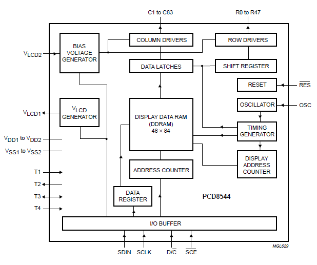
The driver has its 504bytes GDD RAM. However, Its memory comes with 6 blanks and each blank has 84 segments and each segment can store the 8 bit of data. Therefore, the whole LCD data can store in the GDD RAM of the LCD screen.
Output Pins
The input pins of the driver are the same as the LCD pins which are already in the pin configuration section. The output pins of the driver are responsible for every function on the LCD screen. However, four types of output pins exist in the driver. The first part is the Row and Column pins. The row pins are 48 and columns are 84 in numbers. Therefore, all these pins connect to each pixel of the LCD and they are responsible for each output by them. The next part is the power part. The VSS, VDD, and VLCD help to power up the LCD and itself. The third part is the test pins that connect with the ground. In the Nokia5110 LCD, they have no use.
The last part is the oscillator pin, to attach an external oscillator. There will be remaining dummy pins that have no use in the LCD screen. In this Nokia5110 LCD, every kind of symbol is drawable. Even images can also show on the screen but first, it requires to convert into the bitmap format.
Working Principle of Nokia 5510 LCD Display
The word LCD stands for liquid crystal display. Its name describes that every LCD display consists of liquid crystal. When an electric current is passed through these crystals then the magnetic field is produced. This magnetic field-aligned the molecules of liquid crystal forcefully, then when they are aligned precisely then they allow the light to pass through these crystals.
The working phenomena of every LCD display are almost the same. But the voltages which are required to produce the magnetic field are different. On the biases of these voltages, the LCD display shows data which is coming from any type of controller. Two types of data have come from the controller’s fist one is word data and second one graphic data. Each data produces a different magnetic field and the LCD display shows this data according to its magnetic field.
How to use Nokia5110 LCD?
The use of the Nokia5110 LCD is very simple with the library. The library is for Arduino only.
Interfacing with Arduino
To use the LCD with Arduino the following circuit needs to establish. However, some pins are moveable but some will depend on the board/Arduino type.

Programming
The libraries which help to establish the communication are:
#include <SPI.h> // The LCD uses the SPI communication, that's why it is initiated here
#include <Adafruit_GFX.h> // The library uses som functions from the official Adafruit graphics library
#include <Adafruit_PCD8544.h> //The driver display everything on the LCD so this library helps in arduino to do that
The library will require the pins number to operate and a specific object which can help to call each function of them. The rest of them will require to initialize the LCD.
//Here display is the object to and change the pins according to the following sequence:
//CLK,DIN,D/C,CE,RST Adafruit_PCD8544 display = Adafruit_PCD8544(7, 6, 5, 4, 3);
 void setup() { display.begin(); //Initialize the library display
display.setContrast(57); //Set the contrast
display.clearDisplay(); //Clear the buffer of the driver
}
The LCD character contrast is changeable from the programming but LED light changes externally. However to change it add the potentiometer at the LED pin, which is “BL”.
The following code will help to initilize the LCD with Arduino but to use it properly everything needs to define. Therefore, here’s the simple text display for the LCD screen.
display.setTextColor(BLACK); //Set the LCD text color. In Nokia5110 it doesn't necessary
display.setCursor(0,0); //It will set the origin of the text on the LCD
display.setTextSize(2); //The text size will set from the following command.
display.println("ENTER TEXT"); //The text will go here
display.display(); //After everything is set use the following command to show it on the LCD
delay(2000);
display.clearDisplay(); //It will clear the buffer which will also clear the screen.
The above code will only display a simple text. Therefore, to show the image, scrolling and rotating text, the library also helps. In the library, some multiple methods and operations can perform but every operation has some limitations. Like image needs to be in bitmap format, etc.
2D Diagram
