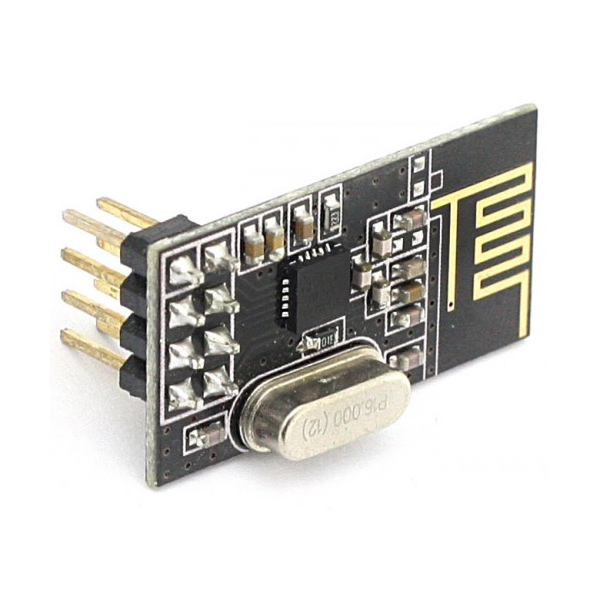
NRF24L01 is one of the legal RF communicators for modern applications. NRF24L01 is the cheapest one and it comes with great features. A single module communicates at 2.4 GHz frequency which makes it legal. It can transmit and receive data by a single module. Transreceiving is not its only ability, it can communicate with a total of 6 other same NRF24L01 modules at a single time. The device interfaces with the Arduino application and covers all kinds of remote-control applications. This wireless module uses SPI communication protocol and offers 10MBs data rate with 125 address range which makes it reliable the most reliable RF module. The RF module uses the GFSK module to transceiver the data.
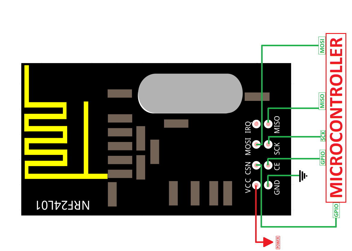
NRF24L01 Pinout Configuration
In NRF24L01 there aren’t any special pins, all pins it offers to communicate are present in all microcontrollers and board. The device will interface with an external microcontroller/Arduino through these pins to operate. It consists of 8 pins. All available pins are:

Power supply pins
VCC
The power pin of the module is VCC, which connects itself with the power supply.
GND
nRF24L01 operates with another microcontroller and it will need a common ground to operate with it. GND pin will solve the requirement of the common ground.
Communication Pins
CE
CE is an enable pin, which activates the transmission/receiving of the module. It will only activate the device when there is a HIGH state on itself.
CSN
This pin is for activating the data listening and processing from the microcontroller. To keep the data communication between the microcontroller and the module it should be HIGH.
SCK
It is the clock pulse pin of SPI communication in nRF24L01. The data will move between the module and the microcontroller according to the clock pulse on the SCK pin.
MOSI
The data transmitted from the microcontroller through SPI pins are going to receive by nRF24L01 at the MOSI pin.
MISO
The instructions transmitted from the nRF24L01 using SPI pins are going to receive by the microcontroller at the MISO pin.
IRQ Interrupt Pin
IRQ is an interrupt pin, which generates the event whenever a new data is available for SPI pins. It helps to send feedback to the transmitter.
NRF24L01 RF Module Feature
- It works at 2.4GHz frequency which makes it legal in almost every country.
- A single module can act as both a transmitter or receiver.
- A built-in antenna can send the data up to 100 meters.
- A module nRF24L01 can communicate with a maximum of 6 other modules at a time.
- It requires 3.3 volts to operate but voltages can only extend up to 3.6V otherwise it won’t take much time to heat up and burn.
- The device has a built-in oscillator of 16MHz.
- The transmission speed of nRF24L01 is 256kbps to 2Mbps.
- The device has 125 channel range which gives the feature of operating 125 different networks at a single place.
- The channel frequencies variate from 2400MHz to 2525MHz.
NRF24L01 Applications
- In the creation of a small mesh network, nRF24L01 is the best choice to use.
- Remote control applications at developing and commercial works wonderfully with nRF24L01.
- Most IoT applications at home level have this wireless module but at a small level only.
How to use the NRF24L01 Communication Module
nRF24L01 is usable with all the microcontrollers and smart boards but to use it, some pins and data information should be understood. To use the module connect it with another microcontroller with SPI protocol. First, give the power input to the devices and then attach their SPI pins according to the given circuit.
After attaching it keep it in mind there are two ways the nRF24L01 can operate. The first one is transmitter and second and receiver. To communicate as a transmitter and receiver the microcontroller should have known first. In the modern application, the Arduino is the only device that supports the most efficient communication of nRF24L01 communication.
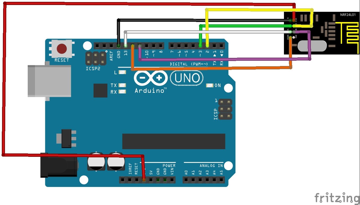
Interfacing with Arduino
There is a lot of work and research about nRF24L01 on the internet that can help to use it in many applications but there is the basis of this module in Arduino every developer should understand. The basic operation of the nRF24L01 is transmitter and receiver, in Arduino, both are achievable through the following methods. Here’s the circuit for Arduino UNO.
How to use as a Transmitter Example
When nRF24L01 will act as a transmitter then it can only transmit data at a single channel to another module. To use it as a transmitter the program in Arduino should have known. After uploading the program there are no ways without programming the modes between transmitter and receiver are changeable. To use it as transmitter the following code should be upload:
#include <nRF24L01.h>
#include <RF24.h>
#include <SPI.h>

RF24 radio(3, 2);

void setup()
{
radio.begin();
radio.openWritingPipe(10101);
radio.stopListening();
}
void loop()
{
const char data[] = "DATA";
radio.write(&data, sizeof(data));
delay(2000);
}
Details about transmitter code
The communication between Arduino and nRF24L01 depends on the following libraries:
#include <nRF24L01.h>
#include <RF24.h>
#include <SPI.h>
As we know that every Arduino board has a specific SPI pin of MISO, MOSI, and SCK. So, Arduino won’t have to tell about them but CSN and CE pins need to initialize. The nRF24L01 library has a built-in function to get the PIN of both CSN and CE which is:
RF24 radio(3, 2);
The number 3 represents the CE pin and 2 represents the CSN pin. Both are changeable according to any digital pins; here they are according to the above-given circuit.
After that module must initialize by using the following command:
radio.begin();
The address is definable with 5 bits for the device at which it should communicate the receiver. Any 5-bits number is useable.
radio.openWritingPipe(10101);
After that module should have to know its mode. Either it is working as a receiver or transmitter. The following command will make the nRF24L01 a transmitter.
radio.stopListening();
Then the device is useable as a transmitter. The only thing known to initialize is sending data. Always keep in mind that only 32 bytes of data are sendable at a time because of module limitation. The following command will help to define that:
const char data[] = "DATA";
radio.write(&data, sizeof(data));
The transmitting data is definable in the setup or loop of the program.
How to use NRF24L01 as a Receiver Example
The above part is all about the transmission method but the receiver method isn’t different from the transmitter. In the transmitter, only three instructions are going to change.
- The address channel, which wasn’t available in the transmitter
- The initialization of the module as a receiver
- Data receiving and checking method
Here’s the following code for the receiver.
#include <nRF24L01.h>
#include <RF24.h>
#include <SPI.h>

RF24 radio(3, 2);

void setup()
{
radio.begin();
radio.openReadingPipe(0,00001);
radio.startListening();
}
void loop()
{
if (radio.available())
{
char data[32] = {0};
radio.read(&data, sizeof(data));
}
}
Detail about receiver code
As you make notice only three parts are different for the receiver from the transmitter.
The first part is the address part:
radio.openReadingPipe(0,10101);
In the address part, there are two parts now. the second one is the address part which defines the address of the transmission device. The first part which is “0” defines the channel. As we talked above that the module offers 6 channels to communicate at a time, the first part of the programming will help to build multiple channels.
The second part is the initialization of the module as a transmitter. To initialize the module as a transmitter, initialize the following command:
radio.startListening();
The third one is the data receiving.
if (radio.available())
It will help to know about the incoming data
radio.read( data, size );
It will help to read the data.
NRF24L01 Example
There are a bunch of applications nRF24L01 is useable but making a mesh is one of the best abilities of nRF24L01 which makes it different from another module. To use it as a mesh total of 3-7 modules should be available. Follow the given image.

Then the following instruction should use to initialize the different channels at the receiver end.
radio.openReadingPipe(0, ADDRESS);
radio.openReadingPipe(1, ADDRESS);
radio.openReadingPipe(2, ADDRESS);
radio.openReadingPipe(3, ADDRESS);
radio.openReadingPipe(4, ADDRESS);
radio.openReadingPipe(5, ADDRESS);
The receiver is unable to differentiate between devices so developers always keep in mind that the data shouldn’t be the same between transmitters.
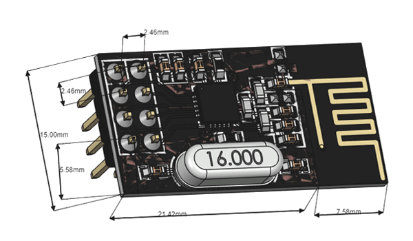
2D Diagram
Alternative Modules:
Excellent tutorial.
Hi!
I have to ask, why do you use this “radio.openReadingPipe(0,00001); ” in the receiver code, and then write “radio.openReadingPipe(0,10101);” , in the details of the receiver code ?