SX1278 LoRa RF Module is one of the latest RF technology and long-range module. SX1278 uses the SPI communication protocol that is suitable for those devices and controllers which has only SPI communication. The module uses an antenna for proper RF communication. It uses multiple types of modulations for data communication which is selectable. SX1278 uses simple RF communication like other modules but its multiple modulation methods and range up to 5KM-10KM makes it best for long-range communication. It uses the Lora spectrum communication technique which extends its range to a maximum of 10KM but it requires a specific channel of 1MHz bandwidth.
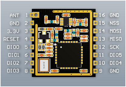
SX1278 LoRa RF Module Pinout Diagram
The SX1278 has a total of 16 pins, which helps to build a proper communication device. The pins will get an interface with a third SPI communication microcontroller or board. Then the controlling device will perform every function through the module. This is a pinout diagram of SX1278 LoRa RF Module.
Pin Configuration Details
For communication, specific pins will help but other pins also have some usage. All pins of SX1278 LoRa module are:
| PINS | DETAILS | |
| Pin 1 | ANT | This pin is to attach to the antenna. |
| Pin 2, 9, 16 | GND | Ground pin of common ground with power supply and controllers. |
| Pin 3 | 3.3V | To power up the device pin 3 will help for power input. |
| Pin 4 | RESET | Pin 4 is to reset the module through an external signal. |
| Pin 5 | DIO0 | To perform the general, I/O function through module the DIO pins will help. The pin DIO0 is customizable as an interrupt pin. |
| Pin 6 | DIO1 | |
| Pin 7 | DIO2 | |
| Pin 8 | DIO3 | |
| Pin 10 | DIO4 | |
| Pin 11 | DIO5 | |
| Pin 12 | SCK | SCK pin is for the clock pulse during the SPI communication. |
| Pin 13 | MISO | MISO means Master in and Slave out. In the case of SX1278, the master will be the controller and slave will be the module. It means through MISO pin data will transfer from Module to the Microcontrollers/Arduino |
| Pin 14 | MOSI | MOSI means Master out Slave In. So, this pin will receive the data from Arduino. |
| Pin 15 | NSS | In SPI communication a chip select/enable pin will help to activate the slave. Therefore, in the SPI, the NSS pin will perform that function. |
SPI Communication Pins
Pin12-15 are pinouts for SPI communication. We can use ths pins to communicate or interface with any microcontroller such as microcontroller, Arduino Uno. We will see an example of Arduino interfacing at the end.
LoRa Module Features
The features of SX1278 are mostly related to modern communication methods and it also has the solution to most of the problems a designer could every face in RF communication. These features don’t require any special external module or hardware. Everything comes within a single SX1278 module.
- The module SX1278 can send the data in nonblocking mode easily.
- It can use different modulations methods on the base of the existing environment.
- The module method it can choose is, GFSK, FSK, OOK, and GMSK.
- The device has an external antenna for communication which extends the range of the module and the Semtech the official company made it.
- The SX1278 uses the LoRa Spectrum modem which can achieve the long-range through from the existing FSK or OOK modulation systems can achieve.
- It operates at 433MHz frequency and uses the half-duplex method for SPI communication.
- The device is a TLL base device and requires 3.3V to operate.
- The range of the module is 5-10KM which makes it suitable for both industrial and commercial levels.
- It uses the 256-bit FIFO method for transmitting the data.
- In the module the user ca decide about error correction rate, spreading factor and bandwidth also.
- The multiple signals can transmit though the same channel without affecting each other.
- The SX1278 supports the Super Anti Jamming Channel at 56db.
SX1278 LoRa RF Module Applications
- The long-range and successful operating ability of the module makes it suitable for every commercial product.
- In Agriculture due to the requirement of long-range and communication SX1278 is vasty available in most of the projects.
- In industries. within IoT communication, the module SX1278 is the best option.
- The commercial meter also communicates with the R long-range RF module.
- To create mesh Star topology or Mesh network SX1278 is reliable.
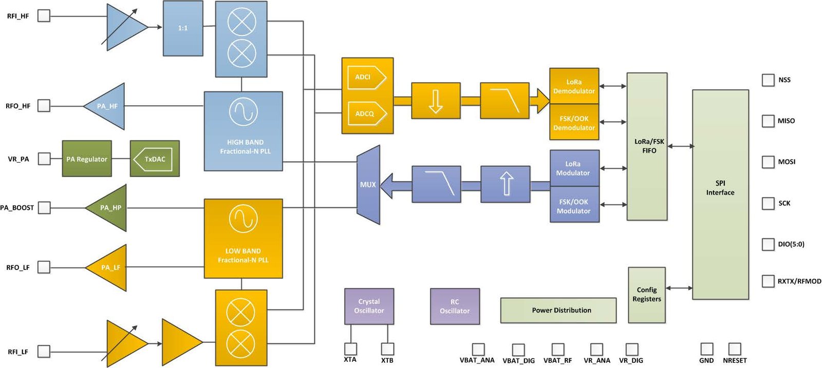
Block Diagram
The block diagram defines the internal structure of the module with pins and the antenna properly.
How To use SX1278 Lora RF Module
Every SPI based microcontroller can control the module but the most common method you will find on the internet is by Arduino. In Arduino, the wiring circuit will according to the SPI communication but the remaining programming part will like serial communication.
Lora RF Module Interfacing with Arduino
Let’s First connect the module with Arduino. The following circuit is for Arduino UNO and always remember Arduino boards have also specific pins like other modules. Just connect SX1278 with the Arduino UNO according to the following diagram.

SX1278 Arduino Library
The is all the requirement on the hardware side for SX1278 to operate. The rest will on Arduino Programming. To program the module from Arduino the following two libraries will help:
#include <SPI.h>
#include <LoRa.h>
The first SPI library is for SPI communication and the other library LoRa will solve the communication issue between module and Arduino. The use library won’t make the data encrypted. To send encrypted data, the data need to encrypted first before passing it to the library. In the above circuit image, SPI pins connections are clear but the other pins like Reset, Chip select and interrupt pin need to define in the programming. These three pins are changeable and are connectable to any digital pins. The Arduino program for these three pins will be:
LoRa.setPins(NSS, RESET, DIO0);
The NSS and Reset pins are for their specific function but the DIO0 pin here is for interrupt. The library Lora is also compatible with almost every LoRa device. To use the module with Arduino its frequency needs to define so it can operate fully. The following command will help to set the frequency level of the module for which its data will transfer. In case of the frequency the module doesn’t have, it will cause the error in operation.
LoRa.begin(433E6);
The value 433E6 will represent the 433MHz frequency which is for SX1278. The module works with SPI protocol which varies with the controller to controller sometimes. To customize the SPI communication the following commands will help:
LoRa.setSPIFrequency(frequency);
LoRa.setSPI(spi);
The first command will help to change the frequency because some device doesn’t operate at 8MHz frequency and SPI will help to get the new SPI pins.
Sending Message with LoRa Module
These all functions we discuss represent the initial conditions of controlling the module. The most important part of programming is the data sending method. To send the data the following commands will help.
LoRa.beginPacket();
LoRa.print("HELLO");
LoRa.endPacket();
The following command helps to send the data but always remember the data can only up to 255 bytes. The LoRa.print command will help to send the string in bytes but the following command is the most used in data sent from the module۔
LoRa.beginPacket();
LoRa.write(byte);
LoRa.write(buffer, length);
LoRa.endPacket();
The length of data should be only 255 bytes which is the most important thing and to send the 255 bytes the developers always must describe the packet start and end. Each packet will send by the microcontroller a time.
Receiving Message Packet with LoRa Module
At the receiving end, the device won’t have much to choose. it will only receive the data and act according to the way it is described in the program.
LoRa.parsePacket()
LoRa.available()
(char)LoRa.read()
LoRa.packetRssi()
The LoRa.parsePacket() will help to describe the packet size. The second command LoRa.avaialable() will help to check the data availability. The (char)Lora.read() will help to read the data and the last command LoRa.packetRssi() will help to describe the Received Signal Strength Indicator (RSSI).
These commands we discussed just describes the general functions of the module with Arduino. To use the module properly at the commercial level and industrial level the problems can be different and bigger we can imagine. The solution to each problem is solvable by the programming. The above methods and discussion are for only simple communication for the sender and receiver. To gain the instructions about advance function look at the official library.
2D Diagram

Alternative Wireless Modules