MC34063A is a monolithic control circuit integrated chip which can buck, boost and invert voltages. It has a switching frequency of up to 100 kHz. Due to its voltage conversion property, it is used in DC-to-DC converters. You can adjust its output voltage by only two external resistors. It operates in a temperature range of 0 °C to 70 °C. It is used in voltage regulation applications and devices like chargers.
MC34063A Pinout
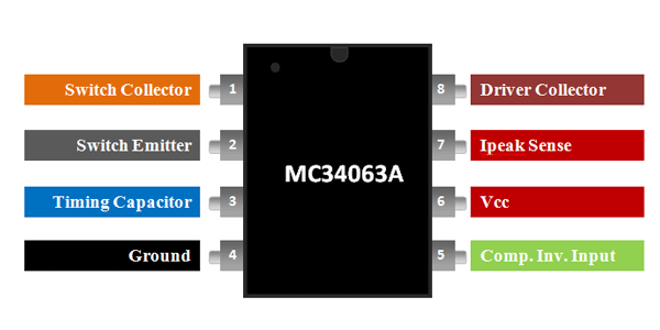
- This buck, boost and inverting regulator is available in three different packages. But the Pinout diagram is same for all the packages.
- All three packages have eight pins.
- The pinout diagram given below depicts all the pins.
MC34063A Pin Configuration Description
In this section, we list the details of all pins and their working functionality. As we mentioned earlier, MC34063 has 8 pins.
Pin#01: Switch Collector
It is the collector input pin of internal high-current switch integrated inside the chip.
Pin#02: Switch Emitter
It is the emitter terminal of internal high-current switch integrated inside the chip and acts as an output pin.
Pin#03: Timing Capacitor
It is the input pin which changes the switching frequency by a timing capacitor attached externally.
Pin#04: GND
It is the ground pin.
Pin#05: Comparator Inverting input
It is the inverting input terminal of a comparator. Connect this pin with a resistor divider network to form a feedback loop.
Pin#06: Vcc
Connect voltage supply at this pin.
Pin#07: Ipk Sense
It is an input pin that monitors the current, keeps it in limits and sets the output current.
Pin# 08: Driver Collector
It is the collector input pin of the driving transistor.
MC34063A Proteus Simulation
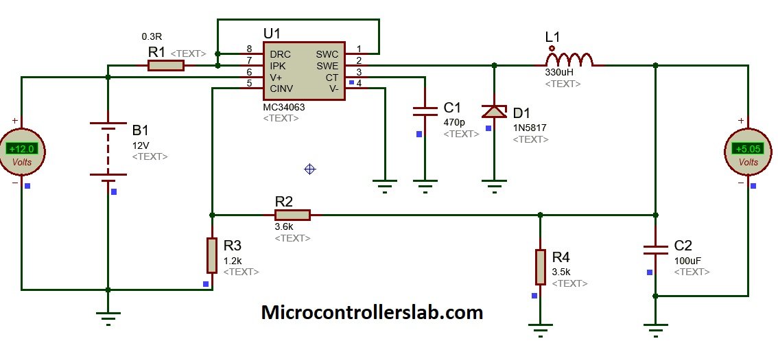
As we have mentioned earlier that we can use this voltage regulator in three operations such as buck, boost and inverting mode. In this example, we design a buck converter example in proteus.
- This circuit shows a buck converter simulation design in proteus.
- It converts 12 volts dc into 5 volts dc.
- You can check the output voltage on the voltmeter as shown in the circuit diagram.
- Although this circuit gives 5 volts dc at the output. But you can change the voltage by changing output resistors and capacitor values.
MC34063 Features
- This device is characterized for operation between 3V to 40V.
- It gives an output current of 1.5 A along with an adjustable output voltage from 1.25V to 40V.
- The reference accuracy is 2 %.
- The frequency of an oscillator is up to 100 kHz.
- Quiescent current is 2.5 mA (Typ.) which is very low.
- It has a low standby current.
- A short circuit fault protection circuit is integrated inside chip.
Where to use MC34063?
IC MC34063A takes an input signal in a range of 3.0V to 40V and gives an adjustable output voltage and output current of up to 1.5A. It requires a minimum number of external components for operation. The primary functions of this IC include step-up voltages, step down voltages and invert voltage. Hence, this IC can be used in all those applications which require these three operations to perform It is also used in DC-to-DC converters.
How to use MC34063A?
In this section, we have provided the example circuits for a buck, boost and inversion operation.
How to select Frequency?
The two resistors connected between pin 8 and 7, and pin 7 and pin 6 controls the frequency of the oscillator. A capacitor connected at pin 3 determines the switching speed.
Output Voltage Calculation
The IC contains a reference regulator and a comparator. The regulator provides 1.25V as an input to the comparator which determines the gain of the output voltage. The output voltage or gain is calculated using the following formula:
VOUT= 1.25V (1 + R2/R1)
Current Sensing Feature
The current sensing pin7 sets the output current. It monitors the current flowing through the inductor and diode which are connected to the output. A resistor is connected at this pin, we place a resistor which sets the maximum current. The value of components is calculated using formulas given in the datasheet.
Filter Capacitor
A 100 µF capacitor is connected at pin6. It filters the voltage supply values by removing noise. The boost function is provided by an inductor connected in between pin1 and 8. The output pin charges up the inductor and a magnetic field is created. When the transistor is turned off, the inductor discharges and the 330 F capacitor gets charged through the diode-connected at the output pin. This process of charging up happens repeatedly until the voltage of the capacitor reaches the peak voltage.
MC34063A Equivalents
UCC25600, LM2596, MCP16252, TC7660 ,MC33063A, SC34063A, SC33063A, NCV33063A
MC34063A Example Circuits
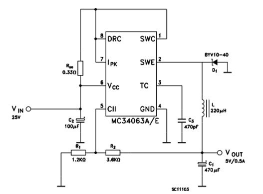
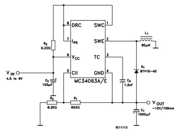
The circuits for buck and inversion operation is also given. For calculating the value of components, refer to the datasheet.
Boost Step-up Converter Example
The circuit given below shows a boost converter example
Buck Step Down Converter Example
Voltage Inverting Operation Mode Circuit
MC34063A Applications
The MC34063A IC is widely used in:
- Consumer and computing electronics
- Portable chargers and blood gas Analyzers
- Telecommunications
- Medical equipment
- Battery operated circuits
- Measurement and test devices
2D Diagram
The two-dimensional diagram given at the end is of 8 lead SOIC package of MC34063A IC.


