TDA1554 is a flexible IC consisting of 4 x 11 W single-ended or 2 x 22 W bridge amplifiers integrated inside the chip. It has two inverting and two non-inverting differential input stages. All the amplifiers are of class B and have a fixed gain of 26dB. used in single-ended or stereo BTL applications. It has an additional mute or standby feature which provides a very low standby current and a mute facility. It has single-ended and BTL configuration modes.
TDA1554 Pinout

TDA1554 Pin Configuration Details
This audio power amplifier consists of 17 pins. As mentioned earlier, TDA1554Q has four audio amplifiers with an option of differential inputs. We can differential inputs with two noninverting and two inverting pins. Consequently, we can use it for single-ended or in bridge mode configuration. You can check the examples given at the end of the tutorial.
Pin#01, 17: NINV1, NINV2
Non-inverting pins
Pin#02, 16: INV1, INV2
Inverting pins
Pin#03, 07, 11: GND, GND1, GND2
Ground pins
Pin#04: RR
Voltage supply ripple rejection
Pin#05, 13: VP1, VP2
Positive input voltage pins 1 and 2
Pin#06, 08, 10, 12: OUT1, OUT2, OUT3, OUT4
Output pins of the four amplifiers
Pin#09, 15: NC
Not connected
Pin#14: M/SS
Mute or stand-by switch disables the outputs.
Features
- Support flexible usage by using only a few components externally.
- Characterized by operation between 6V and 18V.
- Offer protection against electrostatic discharges, over-temperature, reverse polarities and load dump.
- It has a Mute/standby switch.
- Offset voltage is low.
- Fixed gain and good ripple rejection.
- High Output Power
- AC and DC short-circuit-safe to ground.
- Low thermal resistance.
Technical Specification
- The output current is 4A and stand-by current is 10 µA.
- The input impedance lies between 50 kΩ to75 kΩ.
- Operating Voltage Range: 6-18 volts
- voltage supply rejection ratio is 48 dB
Where to use TDA1554?
This IC is intended for use in car radio applications. It has a low offset voltage at outputs which is very important for use in BTL applications. It can handle high energy on outputs. This IC is used in 22Watt stereo amplifiers and 11 watts 4 channel single-ended home audio circuits.
How to use TDA1554 ?
This IC can be used in two modes namely single-ended or Bridge Tied Load (BTL).
Quad single-ended Circuit Example
Here, a quad single-ended application circuit is explained. The circuit given below is a 4-channel 11-watt home audio circuit designed using TDA1554. Each amplifier has four channels. It operates in a DC voltage range of 12 to 18 volts. This voltage supply can be provided from a 12-volt power supply having the capability to deliver 2 Amps. The circuit connections are shown in the diagram below.
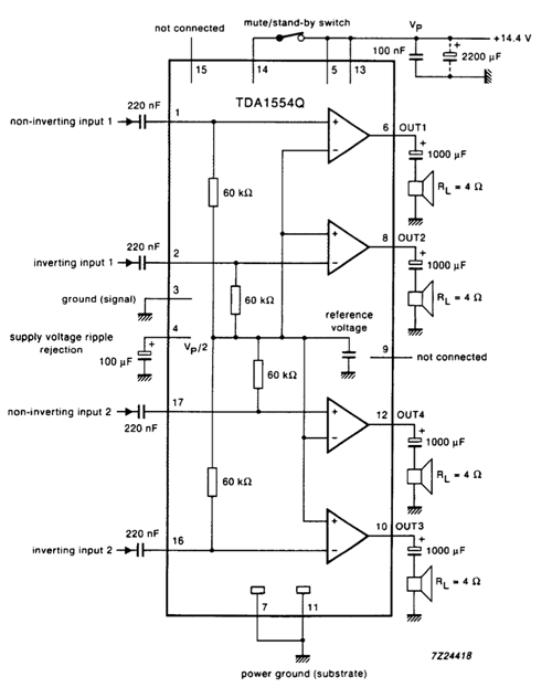
You can see that all the four inputs (two inverting and two non-inverting) are connected to a capacitor of capacitance 220 nF. These capacitors serve as filters. They only allow certain frequencies to pass through them while blocking remaining and remove noise. That is why they are connected in series with the input pins.
The output pins are connected to speakers of the impedance of 4Ω through a 1000µF capacitors. The output capacitors act as an isolator. They prevent the mixing of AC and DC signals by blocking DC signals otherwise harmonics will be generated. The voltage supply rejection is measured by a 100µF capacitor connected at pin4. Higher the value of the capacitor will improve the ripple rejection at lower frequencies. Pin14 is a mute or standby switch. It is connected to the power supply through a switch. When the switch is ON, it will disable the audio outputs. For normal operations, it is OFF.
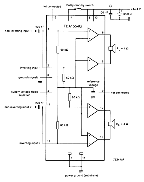
BTL Configuration Circuit Example
The circuit shown below is of BTL configuration. The components are almost same in both circuits. In single-ended configuration, each speaker is driven by a single MOSFET half-bridge while in Bridge-tied load (BTL), the speaker is connected between the two MOSFET half-bridges.
Equivalent and Alternative Options
TDA1554 Applications
It is an audio amplifier IC used in:
- Stereo amplifiers
- Home audio circuits
- Car radios
2D Diagram
