The TEENSY 3.6 development board consists of a 32-bit ARM Cortex M4 programmable microcontroller. It is Arduino compatible having 180MHZ processor along with a floating-point unit. It has a bootloader so you can easily program it through High-speed on-board USB port.
In other words, it has an onboard programmer and debugger. Therefore, we don’t need any additional components to program and use a TEENSY 3.6 development board. A most important feature of this development board is its compatibility with Arduino IDE. Most programs that are written for Arduino Uno work without any changes on Teensy development board.
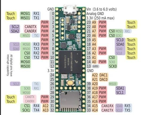
Teensy 3.6 Development Board Pinout Diagram
This picture shows the pinout diagram of TEENSY 3.6 Development Board. As you can see it is a 33 pin development board and unlike Arduino, it supports advanced features such as DMA memory channels, high-resolution ADCs, CAN communication and digital Audio interface.
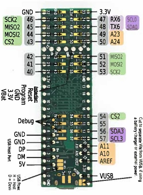
This board also hase additional pins assignment on the backside of the development board. This diagram shows the pinout of backside layout.
Teensy 3.6 Pin Configuration
Serial Communication Pins
It has six serial communication channels and they are accessible through these GPIO pins:
- GPIO0 – RX1
- GPIO1 – TX1
- GPIO9 – RX2
- GPIO10 – TX2
- GPIO7 – RX3,
- GPIO8 – TX3
- GPIO31 – RX4
- GPIO32 – TX4
- GPIO34 – RX5
- GPIO33 – TX5
- GPIO47 – RX6
- GPIO48 – TX6
The signals at these pins are of the TTL level. Two serial ports support a high baud rate and come with FIFO. The transmit pins are interrupt based and receive pins have buffers which prevent waiting in case of short messages. These ports receive and transmit data through the UART protocol.
PWM pins
The board has a total of 22 PWM pins which are D2 to D10, D29, D30, D14, D16, D17, D20 to D23 and D35 to D38.
SPI Ports
It has two SPI communication ports which are:
- SPI Port 1: MISO0, MOSI0, SCK0
- SPI Port 2: MISO1, MOSI1, SCK1
Power pins
They include:
- (1)
: It is a voltage supply pin in case of an external source. It can withstand a voltage source in a range of 3.6V to 6V.
- (2) 3.3V: It consists of an onboard voltage regulator which provides a regulated output voltage of 3.3 V. The maximum current for this regulator is 250mA.
- (3) Analog GND: Connect this to the main ground. It is the ground pin for Analog to Digital and Digital to Analog converter.
- (4) GND: Connect this pin to the ground of the circuit.
- (5) The 5-volt source is also available. Because many sensors require 5 volts power supply. You can get 5 volts from the backside of the board.
Analog Pins
It has 25 analog inputs to two analogs to digital converters with 13-bit resolution and 2 analog outputs which has a 12-bit resolution.
- GPIO_D14 >> Channel_A0
- GPIO_D15 >> Channel_A1
- GPIO_D16>> Channel_A2
- GPIO_D17>> Channel_A3
- GPIO_D18 >> Channel_A4
- GPIO_D19>> Channel_A5
- GPIO_D20>> Channel_A6
- GPIO_D21 >> Channel_A7
- GPIO_D22 >> Channel_A8
- GPIO_D23 >> Channel_A9
- GPIO_X>> Channel_A10 ( Connection available on backside of Teensy 3.6)
- GPIO_X >> Channel_A11 ( Connection available on backside of Teensy 3.6)
- GPIO_D31 >> Channel_A12
- GPIO_D32 >> Channel_A13
- GPIO_D33 >> Channel_A14
- GPIO_D34 >> Channel_A15
- GPIO_D35 >> Channel_A16
- GPIO_D36 >> Channel_A17
- GPIO_D37 >> Channel_A18
- GPIO_D38 >> Channel_A19
- GPIO_D39 >> Channel_A20
- GPIO_D40>> Channel_A21
- GPIO_D42 >> Channel_A22
- GPIO_D49 >> Channel_A23
- GPIO_D50 >> Channel_A24
I/O pins
It has 62 digital input-output pins and all these pins have on-change interrupt feature. But only 42 input/output pins which are breadboard friendly. But you can also access other GPIO pins from the backside of the teensy 3.6 board.
I2C Protocol pins
It has four ports for I2C communication which are:
- GPIO_D19 – SCL0
- GPIO_D18 – SDA0
- GPIO_D37 – SCL1
- GPIO_D38 – SDA1
- GPIO_D3 – SCL2
- GPIO_D4 – SDA2
- GPIO_D57 – SCL3
- GPIO_D56 – SDA3
Touch Sensing Outputs
These pins are eleven in numbers and is used for capacitive touch sensing. These pins are D0, D1, D29, D30, D15 to D19, D22 to D23.
DAC Pins
It has two DAC modules that we can use as a analog output pins. Each DAC has 12-bit resolution. The associated pins on development board are:
- GPIO_D40 >>DAC0
- GPIO_D41 >>DAC1
Status LED
Pin 13 is an LED pin which contains on-board LED.
TEENSY 3.6 Development board Features
The specifications of TEENSY 3.6 Development board are:
- The board has a 1M Flash Memory, 256KB SRAM, 4KB EEPROM and a MK66FX1M0VMD18 microcontroller.
- USB port having full speed of 12 Mbit/sec.
- 4-bit SDIO port for SD card and an Ethernet MAC which has a speed of 100 Mbit/sec.
- 62 Input/output pins with a source/ sink current of 25mA.
- 25 Analog Inputs, 2 Analog Outputs (DACs) with 12-bit resolution, 14 Hardware timers and 22 PWM Outputs.
- 3 ports for
C interface
- 3 ports for SPI Interface in which one has FIFO
- Six serial ports which has fast baud rates.
S audio port which consists of four channel digital audio input and output.
- Real time clock with speed of 180MHz.
- It consists of cryptographic acceleration, CRC Computation unit and a random number generator.
How to Program Teensy 3.6 Board?
The TEENSY 3.6 Development board has 62 I/O pins and a greater number of serial ports as compared to other boards. It has an extra high-speed USB port, real-time 2-channel audio, the SD card, and Ethernet compatibility. Its processing power is high as compared to the UNO, MEGA and NANO Arduino.
It has a USB port for programming which eliminates the need for other programming tools or components. You can program it using Arduino IDE also. You can use it easily with MAC, Linux, and Windows as it has a GUI. Therefore, you can use this board in applications and projects where you need to use more I/O pins, serial ports, and high processing power.
Download and Install Teensy Library for Arduino IDE
As we mentioned earlier, all programming sketches of Arduino IDE and their built-in functions are compatible with teensy 3.6 and 3.2 development boards. If you know Arduino programming, then programming teensy boards will be a piece of cake for you.
But before that, you need to install a teensyduino library for Arduino IDE. To install library go this link this and download library:
After installing the library, you can program this development board like Arduino Uno. If you don’t know how to use Arduino IDE, you can refer to this post:
Applications
It has a wide range of applications including:
- Robotics
- Led strips use this board due to high processing power and direct memory access capabilities
- GPS receivers and ESP Wifi modules also use this board for operation.