I2C (Inter-Integrated Circuit) is a serial communication protocol that allows multiple devices to be connected to a single bus. It is commonly used in embedded systems and other applications where a small number of devices need to communicate with each other.
Data transmission between digital devices can mainly occur in two ways, parallel or serial through a wired medium. Microcontrollers use many serial protocols to communicate with external devices such as sensors and displays and I2C communication is one of them. A language in which a mode of communication is defined between devices and a system is known as a protocol. It specifies the electrical aspects, transfer rate, bit ordering, and bit pattern meaning. For serial data communication, different protocols are used such as TWI, USB, SPI or UART, etc. It has many applications in microcontrollers projects.
I2C communication
The I2C (Inter-integrated circuit pronounced as “eye-squared-see”) is a protocol which allows different slave chips or circuits to communicate with different master chips. It is only used for short-distance communications. It is advantageous in terms of usage of wires, as it requires only 2 wires but 1008 devices can be supported by these 2 wires only.
I2C protocol was invented by Philips semiconductors in the 1980s, to provide easy onboard communications between a CPU and various peripheral chips. I²C stands for Inter-Integrated Circuit. It is a short distance serial interface that requires only two bus lines for bi-directional data transfer. It is used for attaching lower-speed peripheral ICs to microcontrollers in short-distance communication. Low-speed peripherals include external EEPROMs, digital sensors, I2C LCD, and temperature sensors.
Three additional modes have been specified in this IC:
- At 1 MHz: ‘Fast mode plus’.
- 3.4 MHz: ‘high-speed mode’.
- 5 MHz: ‘ultra-fast mode’.
I2C supports multi-master communication, meaning that multiple masters can be connected to the bus and can communicate with each other and with the slaves. It also supports clock stretching, allowing a slave to hold the clock line low to indicate that it needs more time to process a command or data.
I2C Communication Pins
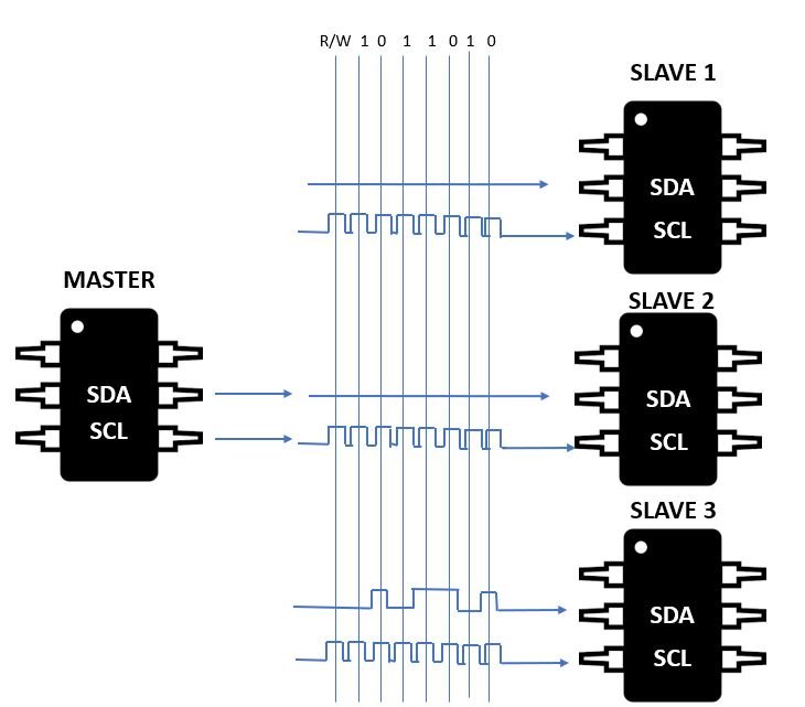
I2C is a simple and efficient protocol that requires only two wires for communication: a clock line and a data line. It is often used in applications where low-cost, low-power communication is required, such as in sensors, displays, and other peripherals. Any number of slaves and any number of masters can be connected to these 2 signals. Unlike UART Communication, this protocol requires a clock signal because this is synchronous communication. By using a clock signal, it achieves high-speed data transfer rate.
- SDA (Serial Data) line: This wire sends data to a slave device. Any data sent from one device to another goes through the SDA wire.
- SCL (Serial Clock) line: It provides the necessary synchronization clock for the data transfer.
We also need to specify the number of bits that we want to send and also the clock frequency for SCL wire.
The bus master generates the clock signal. In some cases, the slaves become slow. This may be because the data given to them is too lengthy or the time span for each clock cycle is too short, then the slaves force the clock low so that they can easily prepare the data before the next cycle starts. This phenomenon is known as “clock stretching”.
The bus drivers of I2C are “open drain”, which means that they can pull a signal line low, but they are unable to drive it high. Suppose if one device is trying to pull the line low whereas another device is trying to drive the line high, then there will be no bus contention. This secures the drivers from getting damaged and protects the system from being over heated. It is shown in figure below:
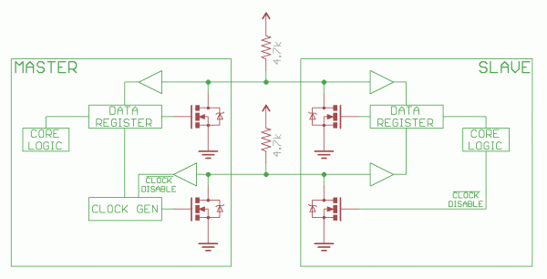
The pull-up resistors connected on the line drives that line to a high signal when no other signal is pulling it low. The resistors could be of different values but commonly we start with a 4.7k resistor and then decrease the value according to our requirements, if needed.
I2C bus signals levels
Some of the times, the devices in a system have different voltage potentials, i.e. the voltage of one device is higher as compared to the other device. But it is possible to connect both the devices without using a level shifting circuit. This is done by connecting a pull up resistor to that device which is lower in voltage level. This method is not sure to work in all cases, but it works just fine in some cases where the lower voltage is greater than the input level of higher voltage system. A good example of this could be a 3.3V accelerometer and a 5V Arduino.
I2C Message Packet Format
Data is sent in either direction on the serial data line (SDA) by the master or slave. Only a Master can start a data transfer and Slaves respond to the Master. It is possible to have multiple Masters on a common bus, but only one could be active at a time. The SCL clock line is always driven by the master.

Both SCL and SDA lines are open-drain drivers and are connected to a positive supply voltage through pull-up resistors. I²C devices can only pull the line low, they cannot drive it high. When no device is pulling on the line, it will float high through the pull-up resistor. This is the reason why pull-up resistors are important in I²C.
The communication through an I2C is very complex. For valid communication, the signals for the devices on the bus must be adhered to a specific protocol. But luckily, most of the devices deal with the small details by themselves and we can concentrate just on the data we want to transmit.

All the messages are split in two frames:
- An address frame.
- Data frames.
In address frame, the master tells the address of the slave to which the data is to be transmitted. And the data frames consist of 8 bit messages which are passed from the master to slave or from slave to the master. When the SCL line goes low, data is placed on the SDA line. And when the SCL line goes high, data is then sampled.
START/STOP CONDITIONS
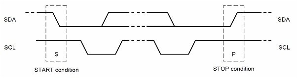
Each I²C command initiated by a master device starts with a START condition and ends with a STOP condition. For both conditions, SCL has to be high. After the Start condition, the bus is considered busy and can be used by another master only after a Stop condition is detected.
The master device pulls SDA (serial data) low and leaves SCL (serial clock) high in order to start the address frame. It alerts all the slave devices that a transmission is going to get started. If there are two or more master devices, then whichever master device brings the SDA low first will take ownership of the bus.
- Start condition: A high to low transition of SDA.
- Stop condition: A low to high transition of SDA.
I2C ADDRESS FRAME
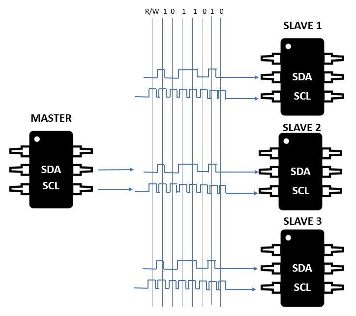
The address frame always comes first, because without an address the device would have no idea to which slave the data is to be transmitted. If the address is 7-bit, the MSB (most significant bit) is read first and then an R/W bit indicates that the operation is either a read or a write operation.
After the start condition, we need to specify the slave address because a single master device can send data to multiple slaves. Each slave will have a unique address. Each slave connected to the bus is software addressable by a unique 7-bit or 10-bit.
7-bit Device Addressing
After the Start condition, the first byte sent is known as the control byte. The first seven bits of the control byte make up the slave address.
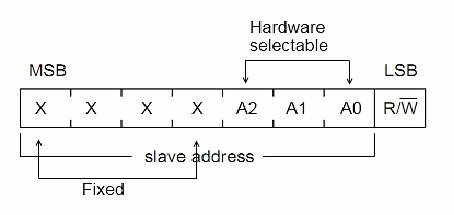
- The first four bits are fixed.
- The next three bits are set by hardware address pins (A0, A1, and A2) which allow the user to modify the I²C address. It allows up to eight devices to operate on the I²C bus.
- The eighth bit (LSB) is a data direction bit (R/W)
- ‘0’ in LSB indicates that the Master will write information to a selected slave
- ‘1’ in LSB indicates that the Master will read data from the slave
- When the receiver gets its address, it has to generate the Acknowledge signal. During this state the transmitter should release the SDA bus to allow the receiver to derive it. When the receiver drives the SDA signal low it acknowledges that the address byte has been received. If the receiver does not drive SDA low, the condition is a no-acknowledge (NACK) and the operation is aborted
Acknowledge     =         0 volts
No Acknowledge   =     High volts.
When a control byte is sent, each device/slave in the system compares the first seven receiving bits with its address. If the address gets matched, the device considers itself addressed by the master. Now, it will behave as slave-receiver or slave-transmitter depending upon the value of the R/W bit.
10-bit Device Addressing
Every I²C device must have a built-in 7 bits address. So according to this, there would be only 128 different I²C device types in the world. But there are many more different I²C devices and there is a high probability that 2 devices have the same address on the I²C bus. To overcome this problem, devices often have multiple built-in addresses that we can select through external configuration pins on the device. To extend the range of available devices address, the I²C specification deduces a 10-bits addressing scheme.

- Instead of one, the two address words are used for device addressing.
- The first address word contains conventional code as “11110” on MSBs to aware the slaves on the bus of 10-bits device address. After that, it contains two MSBs of 10-bit address and R/W bit.
- The second address word contains 8 least significant bits (LSBs) of the 10-bit address. So this addition of bits ensures the backward compatibility with a 7-bit addressing scheme.
I2C DATA FRAMES
Now the data transmission can get started. The clock pulses will be generated by the master regularly. The R/W bit will indicate whether the data is being read or written by the master. If the data is to be read then the slave will put data on the SDA and if the data is to be written then the master will put data on the SDA. The internal register is auto incremented in most cases according to the number of reads or writes.

STOP CONDITION
After the successive transmission of all the data, a stop condition will be generated by the master. The SCL should transit from low to high and then it should remain high, while the SDA transits from low to high, to define the stop condition. It is shown in the above figure.
I2C Data Transmission Steps
Now let us discuss the transmission of data through I2C protocol in a step-by-step manner.
In order to initiate communication on the I2C bus, the master must first send a start condition. A start condition is a specific pattern of signals on the clock and data lines that indicates to all devices on the bus that a new communication is about to begin.

After sending the start condition, the master sends the address of the slave it wants to communicate with. As mentioned earlier, each slave device has a unique 7-bit address, and the master specifies whether it wants to read from or write to the slave by setting the LSB of the address.
The slave device listens for its own address on the bus and responds with an acknowledge signal if it receives its own address. The acknowledge signal is a pulse on the data line that is pulled low by the slave for one clock cycle. This signal indicates to the master that the slave has received its address and is ready to communicate.
If the slave does not receive its own address, or if it is busy and unable to communicate, it does not send an acknowledge signal and the communication is terminated. The master can then retry the communication at a later time or communicate with a different slave
After the master sends the start condition and the address of the slave it wants to communicate with, the slave responds with an acknowledge signal if it receives its own address. The acknowledge signal is a pulse on the data line that is pulled low by the slave for one clock cycle. This signal indicates to the master that the slave has received its address and is ready to communicate.
If the slave does not receive its own address, or if it is busy and unable to communicate, it does not send an acknowledge signal, and the communication is terminated. The master can then retry the communication at a later time or communicate with a different slave.
If the acknowledge signal is received, the master can then proceed to send a command or data to the slave. The slave will respond with an acknowledge signal to indicate that it has received the data. This process can be repeated multiple times to send and receive multiple bytes of data.
It is important to note that the acknowledge signal is optional in some cases. Some slaves may not send an acknowledge signal if they are not able to receive or process the data, or if they are configured to operate in a no-acknowledge mode. In these cases, the master may need to use other methods to detect if the data was received or to check for errors

After the slave responds with an acknowledge signal to indicate that it is ready to communicate, the master can send a command or data to the slave. The command or data is sent as a series of bits on the data line, with each bit being clocked by the master’s clock signal.
The slave listens for the data on the data line and responds with an acknowledge signal to indicate that it has received the data. This process can be repeated multiple times to send and receive multiple bytes of data.
It is important to note that the acknowledge signal is optional in some cases. Some slaves may not send an acknowledge signal if they are not able to receive or process the data, or if they are configured to operate in a no-acknowledge mode. In these cases, the master may need to use other methods to detect if the data was received or to check for errors.
In addition to sending and receiving data, the master can also send special commands to the slave to control its behavior or to request specific information. For example, the master can send a command to read a register on the slave, or to write data to a specific memory location. The slave responds to these commands with the appropriate data or an acknowledge signal to indicate that the command was received and executed.
In an I2C communication, the master and slave can send and receive multiple bytes of data to and from each other. This is useful in applications where a large amount of data needs to be transferred between the devices.
To send multiple bytes of data, the master can simply send each byte one after the other, with the slave responding with an acknowledge signal after each byte to indicate that it has received the data. The slave can also send multiple bytes of data to the master in a similar way, with the master acknowledging each byte as it is received.
It is important to note that the acknowledge signal is optional in some cases. Some slaves may not send an acknowledge signal if they are not able to receive or process the data, or if they are configured to operate in a no-acknowledge mode. In these cases, the master may need to use other methods to detect if the data was received or to check for errors.
In addition to sending and receiving data, the master can also send special commands to the slave to control its behavior or to request specific information. For example, the master can send a command to read a register on the slave, or to write data to a specific memory location. The slave responds to these commands with the appropriate data or an acknowledge signal to indicate that the command was received and executed.

After the master has completed its communication with the slave, it sends a stop condition to end the transmission. A stop condition is a specific pattern of signals on the clock and data lines that indicates to all devices on the bus that the communication is complete.
The stop condition tells the slave that it can stop listening for data and can return to a low-power state. It also releases the bus so that other masters or slaves can initiate communication.
After the stop condition is sent, the master can then initiate a new communication by sending a start condition and the address of a different slave, or it can enter a low-power state to conserve energy.
It is important to note that the stop condition is optional in some cases. Some devices may not send a stop condition if they are configured to operate in a continuous mode, where communication is ongoing and data is transferred continuously without interruption. In these cases, the master or slave may need to use other methods to detect the end of the transmission or to terminate the communication.

I2C Applications
I2C is a widely used protocol in a variety of applications, including:
Embedded systems: I2C is commonly used in embedded systems to communicate with sensors, displays, and other peripherals. Its simplicity and low power consumption make it an ideal choice for these types of applications.
Industrial automation: I2C is used in industrial automation systems to connect sensors, actuators, and other devices to control and monitor processes.
Consumer electronics: I2C is used in a range of consumer electronics devices, such as smartphones, tablets, and laptops, to communicate with sensors, displays, and other peripherals.
Medical devices: I2C is used in medical devices such as monitoring systems, glucose meters, and portable oxygen concentrators to communicate with sensors and other peripherals.
Automotive: I2C is used in automotive systems to communicate with sensors, displays, and other peripherals, such as in engine control systems, infotainment systems, and safety systems.
Aerospace: I2C is used in aerospace applications to communicate with sensors, displays, and other peripherals, such as in aircraft avionics systems and satellite communication systems.
I2C Limitations
I2C is a simple and efficient protocol that is widely used in embedded systems and other applications. However, it does have some limitations that you should be aware of:
Limited distance: I2C is designed for communication over short distances, typically a few meters or less. The length of the bus can be extended using repeaters or other techniques, but this can add cost and complexity to the system.
Limited number of devices: I2C supports a maximum of 128 devices on a single bus, which may be limiting in some applications. However, multiple buses can be used to connect more devices, or other protocols such as SPI (Serial Peripheral Interface) can be used.
Limited speed: The speed of I2C communication is limited by the clock signal, which is generated by the master. The maximum speed of I2C is typically a few MHz, which may not be sufficient for some applications.
Limited power: I2C is designed for low-power communication and is not suitable for applications that require high-power or high-voltage communication.
Complexity: I2C can be more complex to implement than some other serial communication protocols, especially in systems with multiple masters or slaves. It may require additional hardware and software support to manage the communication and to ensure that the devices are properly synchronized.
I2C FAQ
Here are some commonly asked questions about I2C:
What is I2C used for?
I2C is a serial communication protocol that is used to connect multiple devices to a single bus. It is commonly used in embedded systems and other applications where a small number of devices need to communicate with each other, such as in sensors, displays, and other peripherals.
How does I2C work?
I2C works by allowing a master device to control the communication on the bus and to send and receive data to and from slave devices. Each device has a unique 7-bit address, and the master initiates communication by sending a start condition and the address of the slave it wants to communicate with. The slave responds with an acknowledge signal to indicate that it has received the address, and the master can then send data to the slave. The communication is terminated by the master sending a stop condition.
How do I troubleshoot I2C communication problems?
To troubleshoot I2C communication problems, you can try the following steps:
- Check that the devices are properly connected to the bus and that the correct addresses are being used.
- Verify that the devices are configured correctly and are communicating at the same speed.
- Use a scope or logic analyzer to monitor the signals on the bus and ensure that the start and stop conditions, address, and data are being transmitted correctly.
- Check for any hardware issues, such as damaged connectors or broken wires.
- Check for any software issues, such as incorrect driver or library configurations.
- Check for any external factors that may be causing interference, such as electromagnetic interference or power supply issues.
I2C Communication Tutorials: