In this tutorial, we will learn to interface the RC522 RFID Reader Module with Raspberry Pi Pico using MicroPython. RFID (Radio Frequency Identification) technology is one of the most widely used wireless communication technologies in the modern world. These RFID reader modules are very handy in today’s fast-paced world. Due to their fast, accurate, and secure nature, they are widely used with microcontrollers in various fields — from supermarkets for fast check-outs to well-maintained security systems for banks, jails, and server rooms.
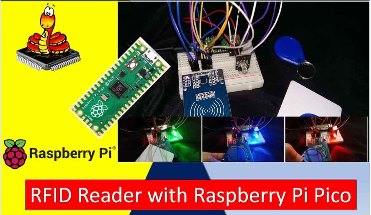
The RFID reader module we will be working with is known as the RC522. We will use it with Raspberry Pi Pico to build a MicroPython project that uses different RFID cards to control an RGB LED and display it in three different colors.
By the end of this tutorial, you will be able to:
- Understand the RC522 RFID reader module — its features and pinout
- Interface the RC522 reader module with Raspberry Pi Pico along with an RGB LED
- Read RFID tag unique IDs
- Control an RGB LED using the RC522 RFID reader module
Recommended Components
The following components are used in this project or are helpful for getting started with Raspberry Pi Pico development.
| Component | How it’s used in this project | Buy on Amazon |
|---|---|---|
| Raspberry Pi Pico | The RP2040 microcontroller board used in this tutorial. | Check Price |
| RC522 RFID Module | RC522 RFID reader module with cards. | Check Price |
| Breadboard | Solderless breadboard for building the circuit. | Check Price |
| Jumper Wires | Male-to-male / male-to-female wires for the connections. | Check Price |
As an Amazon Associate we earn from qualifying purchases. Prices and availability are accurate as of the date/time indicated and are subject to change.
Prerequisites
Before we start this tutorial, make sure you are familiar with and have the latest version of Python 3 installed on your system and have MicroPython set up on your Raspberry Pi Pico. Additionally, you should have a working Integrated Development Environment (IDE). We will be using Thonny IDE throughout this guide:
If you prefer uPyCraft IDE, you can refer to this guide:
How RFID Works
RFID stands for Radio Frequency Identification. It is a technology that uses electromagnetic fields to automatically identify and track tags attached to objects. An RFID system typically consists of two main components: an RFID reader (also called a transceiver) and RFID tags (cards or key fobs).
The RFID reader generates a radio frequency field. When an RFID tag enters this field, the antenna in the tag picks up energy from the reader’s electromagnetic field and uses it to power the tag’s microchip. The chip then modulates the signal and sends back the stored data, such as a unique identification number, to the reader. This entire process happens wirelessly in a fraction of a second, making RFID an extremely efficient method of identification. Passive RFID tags — like the ones used with the RC522 module — do not require a battery; they are entirely powered by the reader’s field.
RC522 RFID Reader Module
The RC522 is a highly integrated multi-communication RFID module based on the MFRC522 chip from NXP Semiconductors. It supports SPI, I2C, and UART communication interfaces, making it compatible with a wide range of microcontrollers. The module comes with an RFID card tag and a key fob, each with 1 KB of onboard memory.
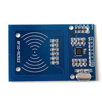

The RC522 module operates at a frequency of 13.56 MHz and can act as both a reader and a writer for MIFARE RFID cards. The RFID cards communicate with the module over a short distance using radio frequency via the principle of mutual induction. The module is widely used in security and commercial products because it can reliably detect and handle errors in RFID tag communication.
RFID Card Tag 1KB Memory Layout
The RFID card included with the RC522 module is a MIFARE Classic 1K card. Its 1 KB of memory is organized into 16 sectors (numbered 0 to 15), and each sector is divided into 4 blocks (numbered 0 to 3). Each block stores 16 bytes. The calculation is: 4 blocks × 16 bytes × 16 sectors = 1024 bytes = 1 KB. The first block of sector 0 contains the manufacturer data and is read-only. Each sector also contains a trailer block (block 3) which holds two 6-byte keys (Key A and Key B) and access control bits, allowing you to set read and write permissions per sector.
RC522 RFID Reader Features
- Uses mutual induction to power passive RFID cards and operates at 13.56 MHz for data transfer.
- RFID cards can be read from both sides of the module at a maximum distance of about 5 cm.
- Requires only 3.3V operating voltage, making it directly compatible with Raspberry Pi Pico.
- Features an auto-sleep mode for low power consumption.
- Supports three communication interfaces: UART, SPI, and I2C, for compatibility with virtually any microcontroller.
- Supports data transfer speeds up to 10 Mb/s in SPI mode.
- On-board CRC coprocessor for error detection and correction.
RC522 RFID Module Applications
- Access control and security systems (door locks, safes, server room access).
- Employee and student attendance tracking systems.
- Inventory management and retail item tracking.
- Parking and ticketing systems.
- Airport baggage tracking and logistics.
- Smart card payment systems.
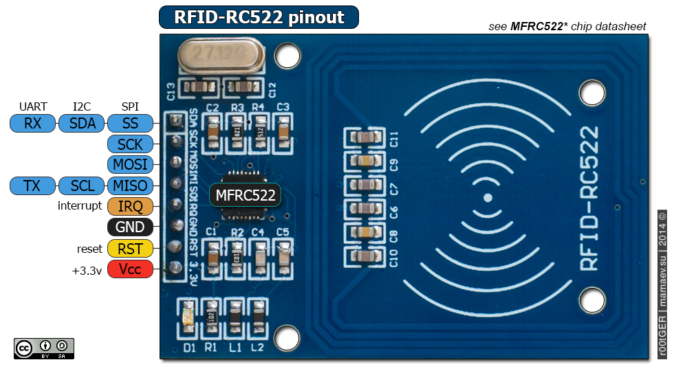
Pinout
The RC522 module has two types of pins: power pins and communication pins. Although the module contains an onboard microcontroller (the MFRC522 chip), it is not a standalone device — it must be controlled by an external microcontroller such as the Raspberry Pi Pico.
The pinout of the MFRC522/RC522 RFID card reader is shown below:
| Pin | Description |
| VCC | Power supply pin. Connect to 3.3V. Some module versions label this as 3V3. |
| RST | Reset pin. Resets the module when pulled low. Useful for error recovery. |
| GND | Common ground. Connect to the GND of the microcontroller and power supply. |
| IRQ | Interrupt request pin. Can wake the module from sleep mode when a card is detected. Often left unconnected in simple projects. |
| MISO | SPI data output (Master In Slave Out). Sends data from the module to the microcontroller. Also used as the I2C clock line or UART TX depending on the communication mode. |
| MOSI | SPI data input (Master Out Slave In). Receives data from the microcontroller. |
| SCK | SPI clock pin. The clock signal is driven by the microcontroller (master). |
| SS (SDA) | SPI Chip Select (active low). Used to select the RC522 module for communication. Also functions as the I2C SDA pin or UART RX pin depending on the selected communication interface. |
For more information, refer to the full RC522 module guide:
RC522 RFID Reader Module — Full Guide
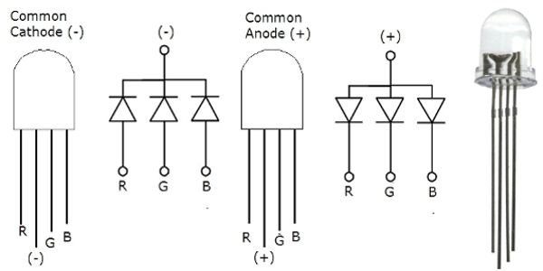
Introducing RGB LED
An RGB LED is a light-emitting diode capable of emitting red, green, and blue light. It actually contains three individual LED chips — one for each color — housed inside a single transparent package. By independently controlling the brightness of each channel, you can mix colors to produce virtually any visible color. In this project, we use only single-color output (red, green, or blue) based on which RFID tag is presented.
The RGB LED has four pins. One is the common pin (either anode or cathode depending on the type), and the other three control each color channel.
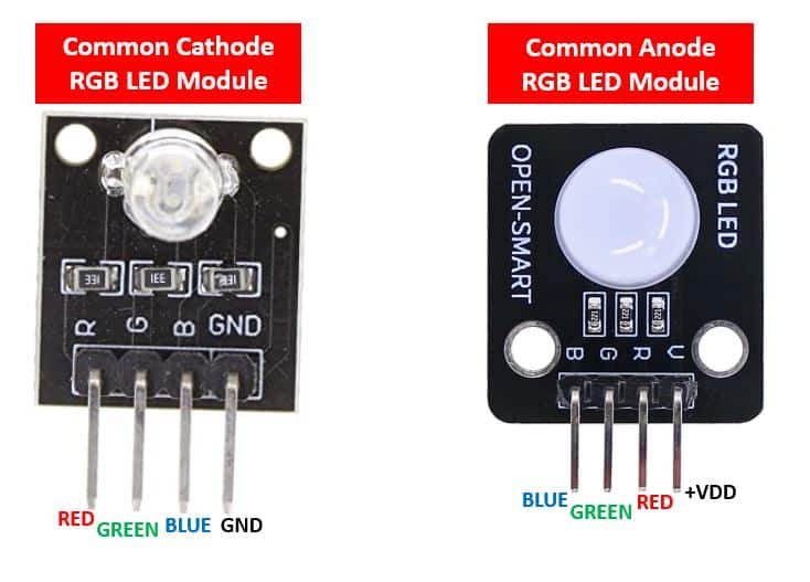
There are two types of RGB LEDs available:
- Common Anode: The anode pin is shared across all three LEDs and connects to the positive supply (Vdd). The individual color cathodes connect to the microcontroller GPIO pins. To turn on a color, you set the corresponding pin LOW. To turn it off, set it HIGH.
- Common Cathode: The cathode pin is shared and connects to GND. The individual color anodes connect to GPIO pins. To turn on a color, set the corresponding pin HIGH.
Pinout
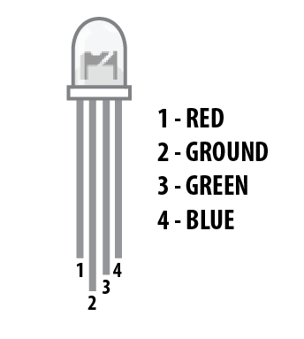
| Pin | Description |
| 1 | Red color select pin. Connect to a digital output GPIO on the microcontroller. |
| 2 | Common pin — GND for common cathode type, or Vdd (5V) for common anode type. |
| 3 | Blue color select pin. Connect to a digital output GPIO on the microcontroller. |
| 4 | Green color select pin. Connect to a digital output GPIO on the microcontroller. |
Important Note: Always use current-limiting resistors (minimum 220 ohm) on each color pin when using a bare RGB LED (not a module). Without resistors, excessive current will damage the LED. The higher the resistance, the lower the brightness.
RGB LED Module
The RGB LED is also available as a pre-built module that already includes current-limiting resistors on each color channel. These modules come in both common anode and common cathode variants and are the easiest way to get started without worrying about resistor calculations.
Related RGB LED guides:
- RGB LED interfacing with MSP430G2 LaunchPad
- RGB LED interfacing with PIC Microcontroller
- WS2812B Addressable RGB LED Interfacing with Arduino
Interfacing RC522 RFID Module and RGB LED with Raspberry Pi Pico
The following components are required for this project:
- Raspberry Pi Pico
- RC522 RFID Reader module
- RGB LED Module (Common Cathode)
- Breadboard
- Jumper wires
The RC522 module requires an operating voltage between 2.5V and 3.3V, so connect its VCC pin directly to the 3.3V pin of the Raspberry Pi Pico. Do not connect it to 5V — this can permanently damage the module. All ground connections between the devices must be shared.
Communication between the Raspberry Pi Pico and the RC522 module uses the SPI (Serial Peripheral Interface) protocol. SPI is a synchronous, full-duplex protocol that uses four main lines: clock (SCK), data from master to slave (MOSI), data from slave to master (MISO), and chip select (CS/SS).
Raspberry Pi Pico SPI Pins
Raspberry Pi Pico supports two SPI peripherals (SPI0 and SPI1). Both are accessible via multiple GPIO pins as shown in the table below. You select which GPIO pins to use in your MicroPython code when initializing the SPI bus.
| SPI Controller | GPIO Pins |
| SPI0_RX (MISO) | GP0/GP4/GP16 |
| SPI0_TX (MOSI) | GP3/GP7/GP19 |
| SPI0_SCK | GP2/GP6/GP18 |
| SPI0_CSn (SS) | GP1/GP5/GP17 |
| SPI1_RX (MISO) | GP8/GP12 |
| SPI1_TX (MOSI) | GP11/GP15 |
| SPI1_SCK | GP10/GP14 |
| SPI1_CSn (SS) | GP9/GP13 |

Raspberry Pi Pico with RC522 Module
| RC522 RFID Reader Module | Raspberry Pi Pico |
| VCC | 3.3V |
| RST | GP0 |
| GND | GND |
| IRQ | Not connected |
| MISO | GP4 |
| MOSI | GP3 |
| SCK | GP2 |
| SDA (SS/CS) | GP1 |
Raspberry Pi Pico with RGB LED Module (Common Cathode)
| RGB LED Module Pin | Raspberry Pi Pico |
| R (Red) | GP13 |
| G (Green) | GP12 |
| B (Blue) | GP11 |
| – (GND) | GND |
Schematic Diagram


Installing the MicroPython MFRC522 Library
This project requires the MicroPython MFRC522 library to communicate with the RC522 module. You can download it from GitHub.
To install the library on your Raspberry Pi Pico:
- Open a new file in Thonny IDE.
- Paste the full library code (shown below) into the editor.
- Save the file directly to the Raspberry Pi Pico as mfrc522.py inside the lib folder. If the
libfolder does not exist, create it first by navigating to the Pico’s file system in Thonny and right-clicking to create a new directory.
mfrc522.py
from machine import Pin, SPI
from os import uname


class MFRC522:

    DEBUG = False
    OK = 0
    NOTAGERR = 1
    ERR = 2

    REQIDL = 0x26
    REQALL = 0x52
    AUTHENT1A = 0x60
    AUTHENT1B = 0x61

    PICC_ANTICOLL1 = 0x93
    PICC_ANTICOLL2 = 0x95
    PICC_ANTICOLL3 = 0x97


    def __init__(self, sck, mosi, miso, rst, cs,baudrate=1000000,spi_id=0):

        self.sck = Pin(sck, Pin.OUT)
        self.mosi = Pin(mosi, Pin.OUT)
        self.miso = Pin(miso)
        self.rst = Pin(rst, Pin.OUT)
        self.cs = Pin(cs, Pin.OUT)

        self.rst.value(0)
        self.cs.value(1)

        board = uname()[0]

        if board == 'WiPy' or board == 'LoPy' or board == 'FiPy':
            self.spi = SPI(0)
            self.spi.init(SPI.MASTER, baudrate=1000000, pins=(self.sck, self.mosi, self.miso))
        elif (board == 'esp8266') or (board == 'esp32'):
            self.spi = SPI(baudrate=100000, polarity=0, phase=0, sck=self.sck, mosi=self.mosi, miso=self.miso)
            self.spi.init()
        elif board == 'rp2':
            self.spi = SPI(spi_id,baudrate=baudrate,sck=self.sck, mosi= self.mosi, miso= self.miso)
        else:
            raise RuntimeError("Unsupported platform")

        self.rst.value(1)
        self.init()

    def _wreg(self, reg, val):
        self.cs.value(0)
        self.spi.write(b'%c' % int(0xff & ((reg << 1) & 0x7e)))
        self.spi.write(b'%c' % int(0xff & val))
        self.cs.value(1)

    def _rreg(self, reg):
        self.cs.value(0)
        self.spi.write(b'%c' % int(0xff & (((reg << 1) & 0x7e) | 0x80)))
        val = self.spi.read(1)
        self.cs.value(1)
        return val[0]

    def _sflags(self, reg, mask):
        self._wreg(reg, self._rreg(reg) | mask)

    def _cflags(self, reg, mask):
        self._wreg(reg, self._rreg(reg) & (~mask))

    def _tocard(self, cmd, send):
        recv = []
        bits = irq_en = wait_irq = n = 0
        stat = self.ERR

        if cmd == 0x0E:
            irq_en = 0x12
            wait_irq = 0x10
        elif cmd == 0x0C:
            irq_en = 0x77
            wait_irq = 0x30

        self._wreg(0x02, irq_en | 0x80)
        self._cflags(0x04, 0x80)
        self._sflags(0x0A, 0x80)
        self._wreg(0x01, 0x00)

        for c in send:
            self._wreg(0x09, c)
        self._wreg(0x01, cmd)

        if cmd == 0x0C:
            self._sflags(0x0D, 0x80)

        i = 2000
        while True:
            n = self._rreg(0x04)
            i -= 1
            if ~((i != 0) and ~(n & 0x01) and ~(n & wait_irq)):
                break

        self._cflags(0x0D, 0x80)

        if i:
            if (self._rreg(0x06) & 0x1B) == 0x00:
                stat = self.OK
                if n & irq_en & 0x01:
                    stat = self.NOTAGERR
                elif cmd == 0x0C:
                    n = self._rreg(0x0A)
                    lbits = self._rreg(0x0C) & 0x07
                    if lbits != 0:
                        bits = (n - 1) * 8 + lbits
                    else:
                        bits = n * 8
                    if n == 0:
                        n = 1
                    elif n > 16:
                        n = 16
                    for _ in range(n):
                        recv.append(self._rreg(0x09))
            else:
                stat = self.ERR

        return stat, recv, bits

    def _crc(self, data):
        self._cflags(0x05, 0x04)
        self._sflags(0x0A, 0x80)
        for c in data:
            self._wreg(0x09, c)
        self._wreg(0x01, 0x03)
        i = 0xFF
        while True:
            n = self._rreg(0x05)
            i -= 1
            if not ((i != 0) and not (n & 0x04)):
                break
        return [self._rreg(0x22), self._rreg(0x21)]

    def init(self):
        self.reset()
        self._wreg(0x2A, 0x8D)
        self._wreg(0x2B, 0x3E)
        self._wreg(0x2D, 30)
        self._wreg(0x2C, 0)
        self._wreg(0x15, 0x40)
        self._wreg(0x11, 0x3D)
        self.antenna_on()

    def reset(self):
        self._wreg(0x01, 0x0F)

    def antenna_on(self, on=True):
        if on and ~(self._rreg(0x14) & 0x03):
            self._sflags(0x14, 0x03)
        else:
            self._cflags(0x14, 0x03)

    def request(self, mode):
        self._wreg(0x0D, 0x07)
        (stat, recv, bits) = self._tocard(0x0C, [mode])
        if (stat != self.OK) | (bits != 0x10):
            stat = self.ERR
        return stat, bits

    def anticoll(self, anticolN):
        ser_chk = 0
        ser = [anticolN, 0x20]
        self._wreg(0x0D, 0x00)
        (stat, recv, bits) = self._tocard(0x0C, ser)
        if stat == self.OK:
            if len(recv) == 5:
                for i in range(4):
                    ser_chk = ser_chk ^ recv[i]
                if ser_chk != recv[4]:
                    stat = self.ERR
            else:
                stat = self.ERR
        return stat, recv

    def PcdSelect(self, serNum, anticolN):
        backData = []
        buf = [anticolN, 0x70]
        for i in serNum:
            buf.append(i)
        pOut = self._crc(buf)
        buf.append(pOut[0])
        buf.append(pOut[1])
        (status, backData, backLen) = self._tocard(0x0C, buf)
        if (status == self.OK) and (backLen == 0x18):
            return 1
        else:
            return 0

    def SelectTag(self, uid):
        byte5 = 0
        for i in uid:
            byte5 = byte5 ^ i
        puid = uid + [byte5]
        if self.PcdSelect(puid, self.PICC_ANTICOLL1) == 0:
            return (self.ERR, [])
        return (self.OK, uid)

    def tohexstring(self, v):
        s = "["
        for i in v:
            if i != v[0]:
                s = s + ", "
            s = s + "0x{:02X}".format(i)
        s = s + "]"
        return s

    def SelectTagSN(self):
        valid_uid = []
        (status, uid) = self.anticoll(self.PICC_ANTICOLL1)
        if status != self.OK:
            return (self.ERR, [])
        if self.DEBUG: print("anticol(1) {}".format(uid))
        if self.PcdSelect(uid, self.PICC_ANTICOLL1) == 0:
            return (self.ERR, [])
        if self.DEBUG: print("pcdSelect(1) {}".format(uid))
        if uid[0] == 0x88:
            valid_uid.extend(uid[1:4])
            (status, uid) = self.anticoll(self.PICC_ANTICOLL2)
            if status != self.OK:
                return (self.ERR, [])
            if self.DEBUG: print("Anticol(2) {}".format(uid))
            rtn = self.PcdSelect(uid, self.PICC_ANTICOLL2)
            if self.DEBUG: print("pcdSelect(2) return={} uid={}".format(rtn, uid))
            if rtn == 0:
                return (self.ERR, [])
            if self.DEBUG: print("PcdSelect2() {}".format(uid))
            if uid[0] == 0x88:
                valid_uid.extend(uid[1:4])
                (status, uid) = self.anticoll(self.PICC_ANTICOLL3)
                if status != self.OK:
                    return (self.ERR, [])
                if self.DEBUG: print("Anticol(3) {}".format(uid))
                if self.MFRC522_PcdSelect(uid, self.PICC_ANTICOLL3) == 0:
                    return (self.ERR, [])
                if self.DEBUG: print("PcdSelect(3) {}".format(uid))
        valid_uid.extend(uid[0:5])
        return (self.OK, valid_uid[:len(valid_uid)-1])

    def auth(self, mode, addr, sect, ser):
        return self._tocard(0x0E, [mode, addr] + sect + ser[:4])[0]

    def authKeys(self, uid, addr, keyA=None, keyB=None):
        status = self.ERR
        if keyA is not None:
            status = self.auth(self.AUTHENT1A, addr, keyA, uid)
        elif keyB is not None:
            status = self.auth(self.AUTHENT1B, addr, keyB, uid)
        return status

    def stop_crypto1(self):
        self._cflags(0x08, 0x08)

    def read(self, addr):
        data = [0x30, addr]
        data += self._crc(data)
        (stat, recv, _) = self._tocard(0x0C, data)
        return stat, recv

    def write(self, addr, data):
        buf = [0xA0, addr]
        buf += self._crc(buf)
        (stat, recv, bits) = self._tocard(0x0C, buf)
        if not (stat == self.OK) or not (bits == 4) or not ((recv[0] & 0x0F) == 0x0A):
            stat = self.ERR
        else:
            buf = []
            for i in range(16):
                buf.append(data[i])
            buf += self._crc(buf)
            (stat, recv, bits) = self._tocard(0x0C, buf)
            if not (stat == self.OK) or not (bits == 4) or not ((recv[0] & 0x0F) == 0x0A):
                stat = self.ERR
        return stat

    def writeSectorBlock(self, uid, sector, block, data, keyA=None, keyB=None):
        absoluteBlock = sector * 4 + (block % 4)
        if absoluteBlock > 63:
            return self.ERR
        if len(data) != 16:
            return self.ERR
        if self.authKeys(uid, absoluteBlock, keyA, keyB) != self.ERR:
            return self.write(absoluteBlock, data)
        return self.ERR

    def readSectorBlock(self, uid, sector, block, keyA=None, keyB=None):
        absoluteBlock = sector * 4 + (block % 4)
        if absoluteBlock > 63:
            return self.ERR, None
        if self.authKeys(uid, absoluteBlock, keyA, keyB) != self.ERR:
            return self.read(absoluteBlock)
        return self.ERR, None

    def MFRC522_DumpClassic1K(self, uid, Start=0, End=64, keyA=None, keyB=None):
        for absoluteBlock in range(Start, End):
            status = self.authKeys(uid, absoluteBlock, keyA, keyB)
            print("{:02d} S{:02d} B{:1d}: ".format(absoluteBlock, absoluteBlock//4, absoluteBlock % 4), end="")
            if status == self.OK:
                status, block = self.read(absoluteBlock)
                if status == self.ERR:
                    break
                else:
                    for value in block:
                        print("{:02X} ".format(value), end="")
                    print("  ", end="")
                    for value in block:
                        if (value > 0x20) and (value < 0x7f):
                            print(chr(value), end="")
                        else:
                            print('.', end="")
                    print("")
            else:
                break
        if status == self.ERR:
            print("Authentication error")
            return self.ERR
        return self.OK
RFID RC522 RGB LED Control
In this project, the Raspberry Pi Pico reads RFID tag IDs and controls an RGB LED accordingly. One specific card will light the LED green, another will light it blue, and any unknown card will trigger the red light. The appropriate message is also printed in the Thonny Shell terminal each time a tag is scanned.
MicroPython Code: Reading RFID Tag IDs
Open Thonny IDE and go to File > New to create a new file. This first program detects and displays the unique ID of any RFID card brought near the RC522 module. Run this program first to discover the IDs of your specific tags before using the LED control program.
from mfrc522 import MFRC522
import utime

reader = MFRC522(spi_id=0, sck=2, miso=4, mosi=3, cs=1, rst=0)

print("Bring TAG closer...")
print("")

while True:
    reader.init()
    (stat, tag_type) = reader.request(reader.REQIDL)
    if stat == reader.OK:
        (stat, uid) = reader.SelectTagSN()
        if stat == reader.OK:
            card = int.from_bytes(bytes(uid), "little", False)
            print("CARD ID: " + str(card))
    utime.sleep_ms(500)
How the Code Works
We begin by importing the MFRC522 class from the mfrc522 library and the utime module for timing control.
from mfrc522 import MFRC522
import utime
We then create a reader object using the MFRC522 class, specifying the SPI bus ID and pin numbers matching our wiring.
reader = MFRC522(spi_id=0, sck=2, miso=4, mosi=3, cs=1, rst=0)Inside the main loop, the reader is re-initialized on each iteration and then polls for a tag using request(REQIDL). REQIDL means the module requests any idle tag within range. If a tag is detected (stat == reader.OK), the anti-collision procedure runs via SelectTagSN() to resolve any conflicts if multiple tags are present. The returned uid byte list is then converted to a single integer using int.from_bytes() with little-endian byte order, giving us the card’s unique numeric ID. A 500 ms delay prevents the same card from being read repeatedly at high speed.
Demonstration
Save the file and press the Run button in Thonny. Make sure the correct board is selected under Run > Select Interpreter. Bring each RFID tag or card near the RC522 reader. The card ID will be printed in the shell terminal. Note down the IDs for the tags you want to use as “green” and “blue” access cards — you will need them in the next program.

MicroPython Code: RFID RC522 RGB LED Control
Now that you have the card IDs, update the card ID values in the code below to match your specific tags. The program reads each tag presented to the RC522 and controls the RGB LED based on a match:
from machine import Pin
from mfrc522 import MFRC522
import utime
reader = MFRC522(spi_id=0, sck=2, miso=4, mosi=3, cs=1, rst=0)
red = Pin(13, Pin.OUT)
green = Pin(12, Pin.OUT)
blue = Pin(11, Pin.OUT)
print("Bring RFID TAG Closer...")
print("")
while True:
reader.init()
(stat, tag_type) = reader.request(reader.REQIDL)
if stat == reader.OK:
(stat, uid) = reader.SelectTagSN()
if stat == reader.OK:
card = int.from_bytes(bytes(uid), "little", False)
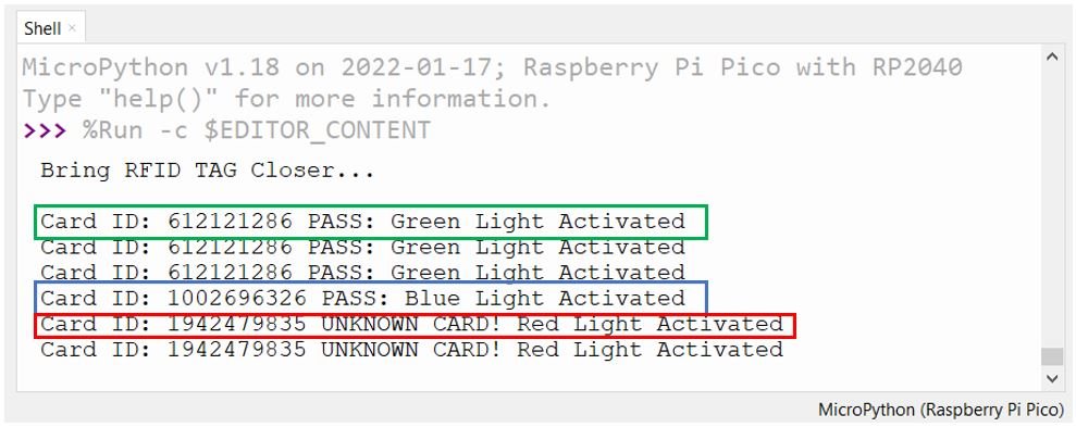
if card == 612121286: # Replace with your green card ID
print("Card ID: " + str(card) + " PASS: Green Light Activated")
red.value(0)
green.value(1)
blue.value(0)
elif card == 1002696326: # Replace with your blue card ID
print("Card ID: " + str(card) + " PASS: Blue Light Activated")
red.value(0)
green.value(0)
blue.value(1)
else:
print("Card ID: " + str(card) + " UNKNOWN CARD! Red Light Activated")
red.value(1)
green.value(0)
blue.value(0)How the Code Works
This code builds on the ID-reading program. Three GPIO pins are configured as outputs to control the RGB LED channels. After reading the card ID, the code checks if it matches one of the two pre-defined authorized IDs. For common cathode type RGB LED modules, setting a pin HIGH turns on that color channel and setting it LOW turns it off. For each color, only one pin is set HIGH while the others remain LOW to produce a pure red, green, or blue output.
Setting the LED to green (set GP12 HIGH, others LOW):
red.value(0)
green.value(1)
blue.value(0)
Setting the LED to blue (set GP11 HIGH, others LOW):
red.value(0)
green.value(0)
blue.value(1)
Setting the LED to red for any unknown or unauthorized card (set GP13 HIGH, others LOW):
red.value(1)
green.value(0)
blue.value(0)
Demonstration
After saving and running the code, bring each RFID tag close to the RC522 reader. The RGB LED will light up in the appropriate color and the Thonny Shell will print a confirmation message.

Troubleshooting
If the RC522 module is not working as expected, here are some common issues and solutions:
- “Unsupported platform” error: This error appears if the mfrc522.py library cannot identify the board. Ensure you are running MicroPython with the rp2 board identifier, which is the standard MicroPython build for Raspberry Pi Pico. Download the latest MicroPython .uf2 firmware from the official Raspberry Pi website and reinstall it.
- No card detected: Verify all SPI wiring connections. Even a single swapped wire between MISO and MOSI will prevent communication. Also confirm that the VCC is connected to 3.3V and not 5V.
- Card detected intermittently: Ensure the card is held within 5 cm of the module. Keep the module away from sources of electromagnetic interference such as motors or power supplies. Also make sure the mfrc522.py library file is saved correctly on the Pico under the lib directory.
- Authentication errors with NFC tags: Standard NFC tags (such as NTAG213) use a different protocol than MIFARE Classic cards. The mfrc522 library is primarily designed for MIFARE Classic cards. NFC-specific tags may not be fully readable with this library without additional modifications.
- RGB LED not changing color: Confirm the LED type — common cathode vs. common anode. In a common cathode LED, setting the pin HIGH turns it on. In a common anode LED, the logic is inverted: setting the pin LOW turns it on. Adjust your code accordingly if needed.
Practical Applications
The RC522 RFID module paired with Raspberry Pi Pico opens up a wide range of practical projects:
- Door Lock System: Use a relay module controlled by the Pico to unlock a door when an authorized RFID tag is scanned, creating a simple access control system.
- Attendance Tracking: Log the tag ID and timestamp to an SD card or send the data over USB serial to a computer for recording employee or student attendance.
- Inventory Management: Attach RFID tags to items and use the reader to track stock levels and movements automatically.
- Vending Machine Authorization: Only allow operation of a machine or dispenser when a valid RFID card is presented.
- Library Book Tracking: Embed RFID tags in books and use the RC522 to scan and log borrowing activity.
You may also like to read:
- NEO-6M GPS Module with Raspberry Pi Pico using MicroPython
- 28BYJ-48 Stepper Motor with Raspberry Pi Pico using MicroPython
- Raspberry Pi Pico Dual Core Programming
- Servo Motor with Raspberry Pi Pico using MicroPython
- HC-05 Bluetooth Interfacing with Raspberry Pi Pico – Control Outputs
- Control DC Motor using L298N Driver with Raspberry Pi Pico and MicroPython
- DS18B20 Temperature Sensor with Raspberry Pi Pico using MicroPython
- DHT11 DHT22 with Raspberry Pi Pico using MicroPython
- HC-SR04 Ultrasonic Sensor with Raspberry Pi Pico using MicroPython
can i use raspberry pi 3b+?
Hello,
Thank you for the great tutorial. I’m using 144 byte NTAG213 NFC tags and having trouble reading data from these tags. I can read the IDs fine. Your code above always returns an “Authentication error”. My tags are not using any authentication and I’m able to read and write to them with my iPhone. Any ideas on how to resolve this issue?
Can you share screenshot of your error?
Hello, I can’t do it as it says unsupported plataform. Is there anything I can do to fix this?
Hi,
I was wondering if instead of an infinite loop we could use the irq to trigger reading from cards. If this is possible how can we do it?
Mike