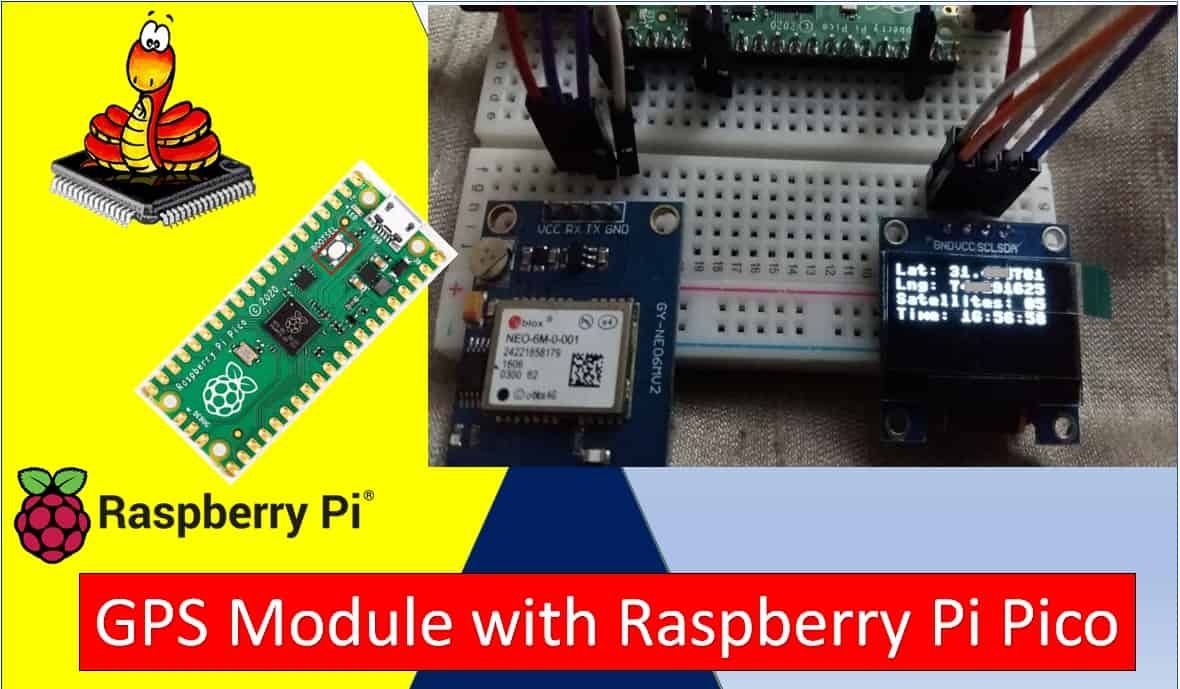
NEO-6M GPS Module with Raspberry Pi Pico using MicroPython
In this tutorial, we will learn about the NEO-6M GPS module and how to interface it with Raspberry Pi Pico to obtain GPS parameters such as latitude, longitude, altitude, date, time, speed, and satellite count. We will cover how GPS technology works, provide an overview of the NEO-6M GPS module including its introduction, pinout, and specifications, and walk through a complete step-by-step guide to interface the NEO-6M GPS module with Raspberry Pi Pico using MicroPython.For demonstration purposes, we will display the GPS location parameters — including Latitude, Longitude, Number of Satellites, and current UTC time — on the Thonny shell console as well as on an SSD1306 OLED display.We have a similar guide with ESP32 using MicroPython:
As an Amazon Associate we earn from qualifying purchases. Prices and availability are accurate as of the date/time indicated and are subject to change.
Prerequisites
Before we start this lesson, make sure you are familiar with and have the latest version of Python 3 installed on your system, have set up MicroPython on your Raspberry Pi Pico, and have a working Integrated Development Environment (IDE). We will be using Thonny IDE throughout this guide. If you have not yet set up your environment, please check the following resources:
The Global Positioning System (GPS) is a satellite-based navigation system that consists of at least 24 operational satellites orbiting the Earth. Each satellite completes two full orbits every 24 hours at an altitude of approximately 20,200 km. These satellites continuously broadcast three key pieces of data: the satellite’s identification number, its precise position in space, and the exact time the signal was transmitted.These signals travel at the speed of light and are picked up by GPS receivers on the ground. By measuring the time it takes for the signal to travel from the satellite to the receiver, the device can calculate its distance from each satellite. With signals from at least three satellites, a GPS receiver can determine its 2D position (latitude and longitude) through a mathematical process called trilateration. With signals from four or more satellites, the receiver can compute a full 3D position including elevation (altitude).In addition to location, a GPS receiver can calculate the user’s speed and direction of travel by tracking position changes over time. GPS is freely accessible to anyone with a compatible receiver and operates 24 hours a day, 7 days a week, across the entire globe. This makes it indispensable for vehicle navigation, GIS data collection, drone guidance, IoT asset tracking, and precision agriculture.
Point to Remember: A GPS receiver locates three or more satellites, calculates the distance to each, and uses this information to determine its own position. This is based on trilateration — not triangulation. Trilateration uses distances (spheres), while triangulation uses angles.
NEO-6M GPS Module Introduction
The NEO-6M GPS module is a compact, high-performance GPS receiver manufactured by u-blox. It is capable of tracking up to 22 satellites across 50 channels simultaneously, making it one of the most popular GPS receivers in the hobbyist and embedded systems community. It is built around the u-blox 6 positioning engine, which delivers excellent sensitivity, fast acquisition times, and low power consumption.The module measures just 16 × 12.2 × 2.4 mm, making it compact enough for wearable devices and small IoT nodes. It supports multiple communication interfaces including UART, SPI, USB, and I2C (DDC), giving developers flexibility when integrating it with different microcontrollers. Its low power draw and built-in Power Saving Mode (PSM) make it especially suitable for battery-powered projects.
Hardware Overview
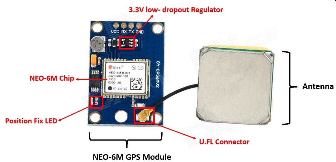
To obtain GPS readings, the NEO-6M module must be used with an antenna. The module includes a U.FL connector for attaching a small external patch antenna. This antenna is critical for receiving the weak satellite signals, especially indoors. For best performance, always use the module outdoors or near a window where the sky is clearly visible.
NEO-6M GPS Chip
At the heart of the module sits the u-blox NEO-6M chip, which handles all satellite tracking and position calculations internally. It can track up to 22 satellites across 50 channels. Key features of this chip include:
High tracking sensitivity of −161 dBm, allowing it to maintain a fix in challenging environments
Low supply current of approximately 45 mA during continuous operation
Position update rate of up to 5 Hz (5 location fixes per second)
Horizontal position accuracy of 2.5 meters CEP (Circular Error Probable)
Built-in Power Saving Mode (PSM) that can reduce current to as low as 11 mA
Internal RTC crystal for fast time-to-first-fix after power cycling
Position Fix LED Indicator
The NEO-6M module includes a blue LED that indicates the GPS fix status. When the module is searching for satellites, the LED remains off. Once a valid GPS fix is obtained (at least three satellites locked), the LED blinks once per second. If the LED never blinks, it usually means the module cannot see the sky and needs to be moved outdoors or placed near a window.
3.3V Low-Dropout Regulator
The module is equipped with a MIC5205 3.3V LDO linear voltage regulator. This accepts input voltages from 3.3V to 5V, making the module compatible with both 3.3V systems like the Raspberry Pi Pico and 5V systems like Arduino. The LDO provides a clean, stable voltage to the NEO-6M chip while rejecting power supply noise that could degrade GPS reception.
Specifications
The table below shows the specifications of the NEO-6M module.
Parameter
Value
Type
GPS Receiver
Supply Voltage
2.7V–3.6V (chip); 3.3V–5V (module via LDO)
Operating Current
~45 mA continuous; ~11 mA Power Save Mode
Operating Temperature
−40°C to +85°C
Channels
50
Max Satellites Tracked
22
Horizontal Position Accuracy
2.5 m CEP
Update Rate
Up to 5 Hz
Communication Protocol
NMEA, UBX Binary, RTCM
Interface
UART, SPI, USB, DDC (I2C)
Cold Start TTFF
27 seconds (typical)
Hot Start TTFF
1 second (typical)
For more information regarding the NEO-6M module refer to its datasheet given here.
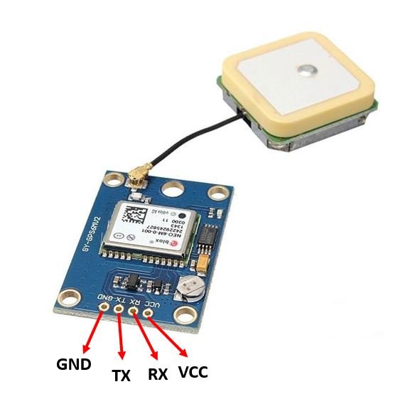
Pinout of NEO-6M Module
The diagram below shows the pinout of the NEO-6M module. It consists of 4 pins: GND, TX, RX, and VCC.
Pin
Description
GND
Ground pin — connect to the GND of the microcontroller.
TX
Transmit pin — sends NMEA data from the GPS module to the microcontroller’s UART RX pin.
RX
Receive pin — used to send configuration commands from the microcontroller to the GPS module.
VCC
Power supply — connect to 3.3V or 5V depending on the module version.
Understanding NMEA Sentences
The NEO-6M GPS module communicates by transmitting GPS data in the text-based NMEA 0183 format (National Marine Electronics Association). Each line of data is called an NMEA sentence. Every sentence begins with a dollar sign ($), followed by a five-character identifier, and all fields are separated by commas. The sentence ends with a checksum for data verification.The most common NMEA sentence types produced by the NEO-6M are:
Sentence
Description
$GPGGA
Global Positioning System Fix Data — provides 3D location, fix quality, and accuracy data
$GPGSA
GPS DOP (Dilution of Precision) and active satellites used in the position fix
$GPGSV
GPS Satellites in View — detailed information about visible satellites
$GPGLL
Geographic Latitude and Longitude
$GPRMC
Recommended Minimum Specific GPS Data — position, velocity, and time
$GPVTG
Track Made Good and Ground Speed
In this project, we parse the $GPGGA sentence because it contains all the essential data we need: latitude, longitude, altitude, number of satellites, and UTC time. Here is an example:
$GPGGA, 103005, 3807.038, N, 07128.99030, E, 1, 07, 1.43, 134.5, M, 42.9, M, , *78
$: Indicates the start of the NMEA sentence
GPGGA: Global Positioning System Fix Data
103005: UTC time — 10:30:05
3807.038, N: Latitude 38 degrees, 07.038 minutes North
07128.99030, E: Longitude 71 degrees, 28.99030 minutes East
42.9, M: Height of geoid above WGS84 ellipsoid in metres
*78: Checksum for data integrity
Note: Raw NMEA latitude and longitude values use DDMM.MMMM format (e.g., 3807.038 = 38 degrees, 07.038 minutes). The convertToDegree() function in our code converts this to decimal degrees automatically.
GPS Signal Accuracy and Dilution of Precision (DOP)
Understanding GPS accuracy is important when building reliable location-aware projects. The accuracy of a GPS fix depends on several factors: the number of visible satellites, their geometric spread across the sky, atmospheric conditions, and any obstructions that may reflect or weaken signals (a phenomenon called multipath interference).The $GPGGA sentence includes an HDOP (Horizontal Dilution of Precision) value that numerically describes the quality of the satellite geometry. A lower HDOP means better accuracy. Here is a general guide to interpreting HDOP values:
HDOP Value
Rating
Typical Accuracy
1
Ideal
Best possible accuracy
1 – 2
Excellent
Suitable for all applications
2 – 5
Good
Acceptable for most applications
5 – 10
Moderate
Less reliable, use with caution
> 10
Poor
Inaccurate, avoid if possible
For most outdoor IoT projects using the NEO-6M, you can expect HDOP values between 1 and 3 when 6 or more satellites are visible, which gives real-world position accuracy of approximately 3–5 meters in open-sky conditions. The $GPGSA sentence provides additional PDOP (Position DOP) and VDOP (Vertical DOP) values if 3D accuracy is needed.
Interfacing NEO-6M Module with Raspberry Pi Pico and OLED
We will need the following components to connect our Raspberry Pi Pico with the OLED Display and NEO-6M GPS module.
Raspberry Pi Pico
NEO-6M GPS Module (with antenna)
SSD1306 OLED Display (128×64, I2C)
Connecting Wires
Breadboard
Raspberry Pi Pico with NEO-6M
The NEO-6M GPS module has 4 terminals which we will connect with the Raspberry Pi Pico. We will connect VCC and GND to the 3.3V and GND pins of the Raspberry Pi Pico respectively. The TX pin of the GPS module connects to the UART RX pin of the Pico, and the RX pin of the GPS module connects to the UART TX pin of the Pico. This cross-connection is standard for all UART-based communication.
Raspberry Pi Pico UART Pins
Raspberry Pi Pico contains two identical UART peripherals with separate 32×8 Tx and 32×12 Rx FIFOs.
UART Pins
GPIO Pins
UART0-TX
GP0/GP12/GP16
UART0-RX
GP1/GP13/GP17
UART1-TX
GP4/GP8
UART1-RX
GP5/GP9
For this guide, we will use UART1 with GP4 as TX and GP5 as RX.
Raspberry Pi Pico
NEO-6M Module
3.3V
VCC
GP5 (UART1 RX)
TX
GP4 (UART1 TX)
RX
GND
GND
Raspberry Pi Pico with NEO-6M and OLED
The OLED display has 4 terminals. We connect the VCC terminal to the common 3.3V rail, SCL to the I2C SCL pin of the Pico, and SDA to the I2C SDA pin. The ground is shared between all devices.
Raspberry Pi Pico I2C Pins
Raspberry Pi Pico has two I2C controllers. Both controllers are accessible through GPIO pins. The following table shows the available GPIO pin options:
I2C Controller
GPIO Pins
I2C0 – SDA
GP0/GP4/GP8/GP12/GP16/GP20
I2C0 – SCL
GP1/GP5/GP9/GP13/GP17/GP21
I2C1 – SDA
GP2/GP6/GP10/GP14/GP18/GP26
I2C1 – SCL
GP3/GP7/GP11/GP15/GP19/GP27
SSD1306 OLED Display
Raspberry Pi Pico
VCC
3.3V
SDA
GP0 (I2C0 SDA)
SCL
GP1 (I2C0 SCL)
GND
GND
Schematic Raspberry Pi Pico with OLED and NEO-6M
Follow the schematic diagram below and connect everything accordingly. You can also use other combinations of SDA/SCL pins and UART pins if needed.
Raspberry Pi Pico with NEO 6M and OLED connection diagram
SSD1306 OLED MicroPython Library
We need to install the SSD1306 OLED library for MicroPython before writing the code. Follow these steps:
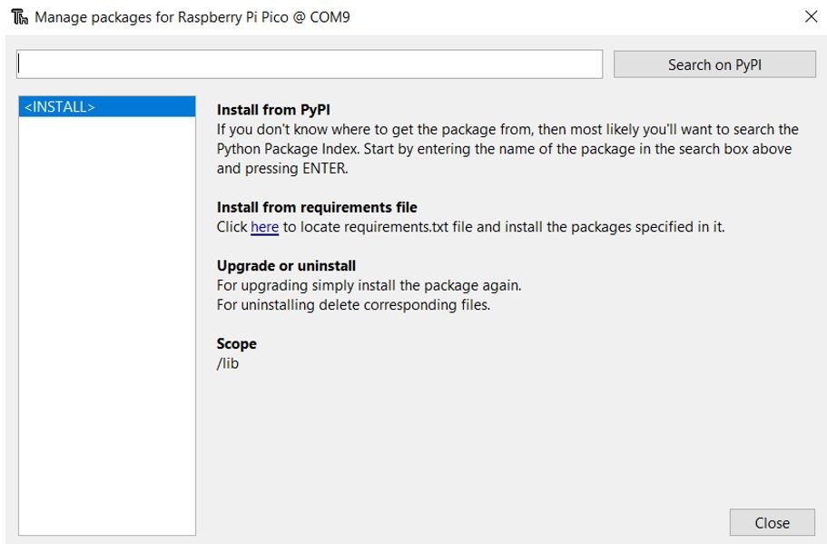
Open Thonny IDE with your Raspberry Pi Pico plugged in. Go to Tools > Manage Packages to open the Thonny Package Manager.
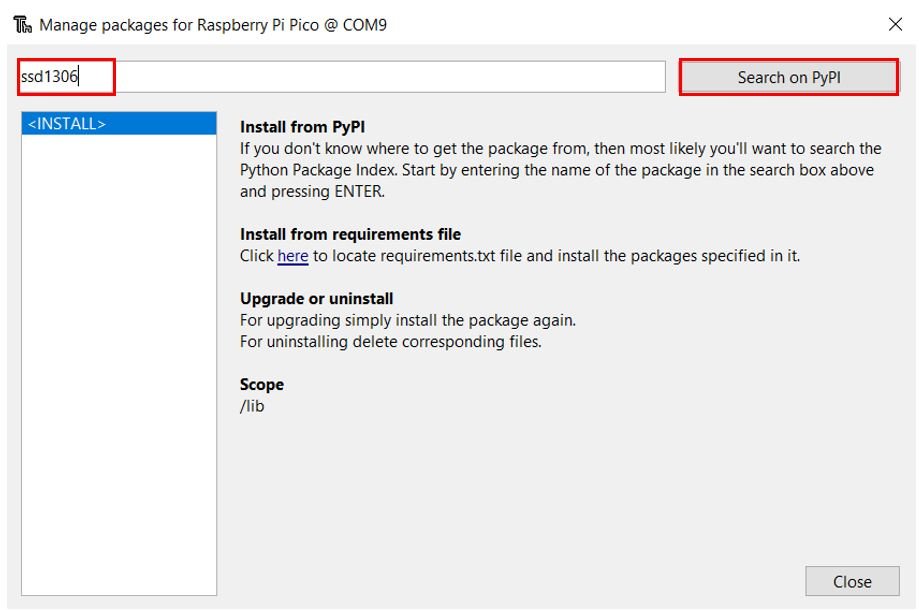
Search for ssd1306 in the search bar and click Search on PyPI.
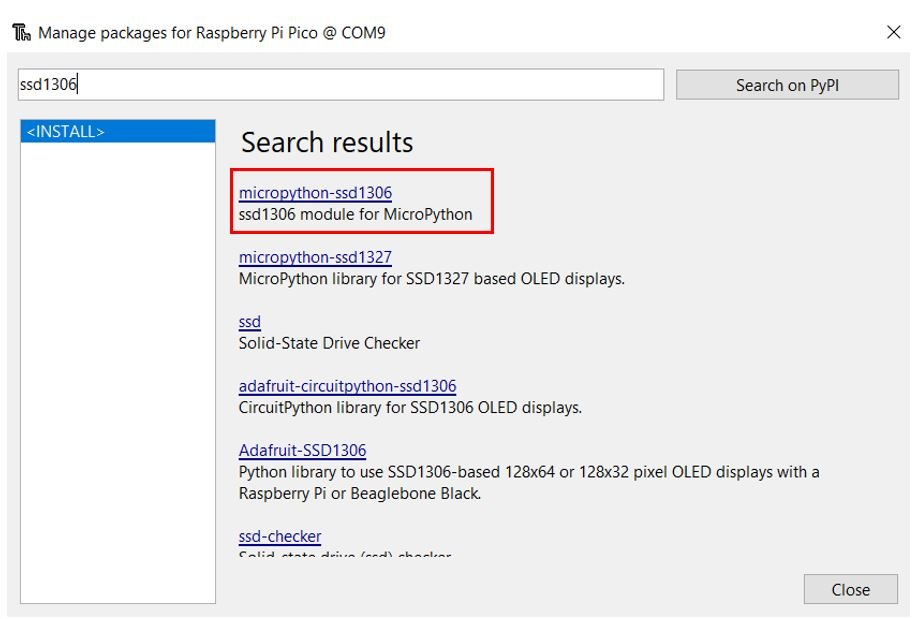
From the search results, click micropython-ssd1306.
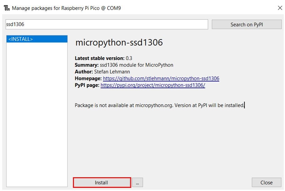
Click Install and wait for the installation to complete.
After a few moments the library will be installed successfully. Now we are ready to program our Raspberry Pi Pico with the OLED display.
MicroPython Script — Obtaining GPS Data from NEO-6M Module
from machine import Pin, UART, I2C
from ssd1306 import SSD1306_I2C
import utime, time
i2c=I2C(0,sda=Pin(0), scl=Pin(1), freq=400000)
oled = SSD1306_I2C(128, 64, i2c)
gpsModule = UART(1, baudrate=9600, tx=Pin(4), rx=Pin(5))
print(gpsModule)
buff = bytearray(255)
TIMEOUT = False
FIX_STATUS = False
latitude = ""
longitude = ""
satellites = ""
GPStime = ""
def getGPS(gpsModule):
global FIX_STATUS, TIMEOUT, latitude, longitude, satellites, GPStime
timeout = time.time() + 8
while True:
gpsModule.readline()
buff = str(gpsModule.readline())
parts = buff.split(',')
if (parts[0] == "b'$GPGGA" and len(parts) == 15):
if(parts[1] and parts[2] and parts[3] and parts[4] and parts[5] and parts[6] and parts[7]):
print(buff)
latitude = convertToDegree(parts[2])
if (parts[3] == 'S'):
latitude = '-' + latitude
longitude = convertToDegree(parts[4])
if (parts[5] == 'W'):
longitude = '-' + longitude
satellites = parts[7]
GPStime = parts[1][0:2] + ":" + parts[1][2:4] + ":" + parts[1][4:6]
FIX_STATUS = True
break
if (time.time() > timeout):
TIMEOUT = True
break
utime.sleep_ms(500)
def convertToDegree(RawDegrees):
RawAsFloat = float(RawDegrees)
firstdigits = int(RawAsFloat/100)
nexttwodigits = RawAsFloat - float(firstdigits*100)
Converted = float(firstdigits + nexttwodigits/60.0)
Converted = '{0:.6f}'.format(Converted)
return str(Converted)
while True:
getGPS(gpsModule)
if(FIX_STATUS == True):
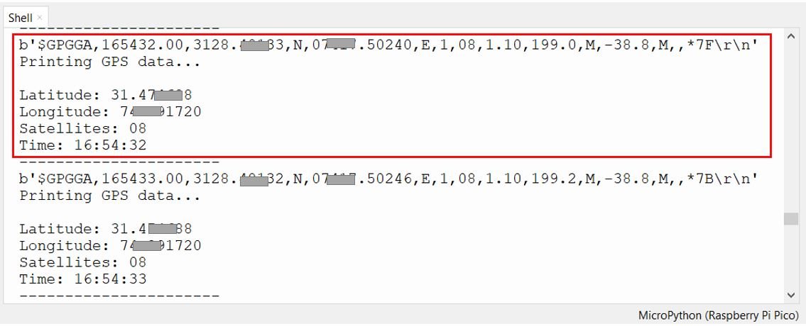
print("Printing GPS data...")
print(" ")
print("Latitude: "+latitude)
print("Longitude: "+longitude)
print("Satellites: " +satellites)
print("Time: "+GPStime)
print("----------------------")
oled.fill(0)
oled.text("Lat: "+latitude, 0, 0)
oled.text("Lng: "+longitude, 0, 10)
oled.text("Satellites: "+satellites, 0, 20)
oled.text("Time: "+GPStime, 0, 30)
oled.show()
FIX_STATUS = False
if(TIMEOUT == True):
print("No GPS data is found.")
TIMEOUT = False
How the Code Works
We start by importing the UART, Pin, and I2C classes from the machine module, along with the utime and time modules for delays and timing. The ssd1306 module provides the OLED display driver.
from machine import Pin, UART, I2C
from ssd1306 import SSD1306_I2C
import utime, time
Initializing OLED
We initialize the I2C bus on channel 0, using GP0 as SDA and GP1 as SCL at 400 kHz. Then we create an SSD1306_I2C object specifying the display resolution (128×64 pixels) and the I2C bus object.
We create a UART object on channel 1, using GP4 as TX and GP5 as RX at the default NEO-6M baud rate of 9600. The NEO-6M uses 9600 baud, 8 data bits, no parity, and 1 stop bit (8N1) by default.
The getGPS() function reads incoming UART data line by line and looks for the $GPGGA sentence. Once a valid sentence with all required fields is found, it extracts latitude, longitude, satellite count, and UTC time, then sets FIX_STATUS to True. A timeout of 8 seconds is built in — if no valid fix is received, the function sets TIMEOUT to True and exits.Note the important bug fix in this version: when the latitude or longitude hemisphere is South (S) or West (W), the value is properly negated by prepending a minus sign string ('-' + latitude) rather than using arithmetic negation, since the values are stored as strings.The convertToDegree() function converts raw NMEA coordinates from DDMM.MMMM format to decimal degrees (DD.DDDDDD) using the formula:
Decimal Degrees = Degrees + (Minutes / 60)
The main while True loop continuously calls getGPS() to fetch the latest GPS data. If a valid fix is obtained, the data is printed to the Thonny shell console and displayed on the OLED screen. If the timeout is reached without a fix, a “No GPS data is found” message is printed instead.
Working with $GPRMC for Speed and Date
While the $GPGGA sentence is ideal for position fixes, the $GPRMC sentence is the most complete single sentence because it includes date, time, position, and speed all in one line. If your project needs speed or date in addition to coordinates, parsing $GPRMC is a practical alternative or supplement to $GPGGA.Here is an example $GPRMC sentence:
The key fields are as follows: field 1 is the UTC time (103005 = 10:30:05), field 2 is the status (A = active/valid, V = void/no fix), fields 3 and 4 are latitude and direction, fields 5 and 6 are longitude and direction, field 7 is speed over ground in knots, field 8 is course over ground in degrees, and field 9 is the date (220226 = 22 February 2026, formatted as DDMMYY).To convert speed from knots to km/h, multiply by 1.852. To convert to miles per hour, multiply by 1.151. You can extend the existing MicroPython code by adding a check for the $GPRMC prefix and extracting these additional fields for more comprehensive GPS data logging.
Troubleshooting Tips
If you encounter issues getting GPS data, here are some common problems and solutions:
No satellite fix indoors: GPS signals cannot penetrate walls reliably. Always test your GPS module outdoors or very close to a window. The module may take several minutes to acquire an initial fix on a cold start.
LED never blinks: If the position fix LED never blinks at 1 Hz, the module has not acquired a satellite lock. Move to an open outdoor area and wait at least 1–2 minutes for the first cold-start fix.
“No GPS data found” message: The 8-second timeout elapsed without a valid GPGGA sentence. Increase the timeout value or ensure the module is outdoors with a clear view of the sky.
Garbled NMEA sentences: Two sentences merging into one buffer read can occur occasionally. Adding a short delay between readline() calls can help mitigate this.
Incorrect latitude/longitude sign: Make sure you are using string-based negation ('-' + latitude) and not arithmetic negation, since the values are stored as strings.
OLED not displaying: Double-check the I2C wiring and confirm the SSD1306 library is installed. Run a quick I2C scan to verify the OLED is detected at address 0x3C.
Intermittent or noisy readings: Keep the GPS antenna cable away from the Raspberry Pi Pico and USB cable, which can emit interference. Use a good quality patch antenna with a clear view of the sky rather than a simple passive ceramic antenna.
Practical Applications
The NEO-6M GPS module combined with the Raspberry Pi Pico opens up a wide range of practical project possibilities:
GPS Data Logger: Store GPS coordinates and timestamps to a microSD card for later analysis — useful for vehicle tracking, hiking route recording, or wildlife monitoring.
Asset Tracking System: Combine with an HC-05 Bluetooth or SIM800L GSM module to transmit GPS coordinates wirelessly for real-time tracking.
Geofencing Alarm: Program the Pico to trigger an alarm when the device moves outside a predefined geographic boundary.
Precision Clock: Use the GPS UTC time signal as a highly accurate time source for a real-time clock, eliminating the drift associated with standard RTC modules.
Autonomous Robot Navigation: Use GPS waypoints to guide a robot to specific outdoor locations.
Weather Station with Location Data: Tag sensor readings with precise GPS coordinates for geographic data analysis.
Bicycle or Motorcycle Computer: Display real-time speed (from $GPRMC), distance traveled, and coordinates on the OLED for a low-cost cycling computer.
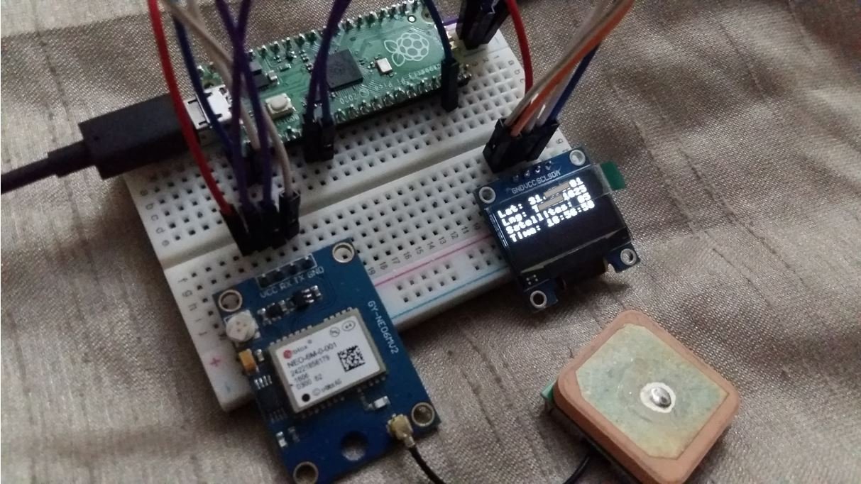
Demo
After copying the code into a new Thonny file, save it to your Raspberry Pi Pico and press the Run button. Take the setup outdoors or near a window. Within a minute or two, GPS coordinates will begin appearing in the Thonny shell console.
Once the code is running, the OLED display will simultaneously show latitude, longitude, satellite count, and current UTC time, updating every few seconds.
To read more GPS-related articles, follow the links below:
struggled with this one, i have bought 3 separate units, wired them up as shown, get no flashing lights, no gps data found ?? any clues would be greatly appreciated


There is a slight error in the code at lines 7 and 40
instead of longitude = -longitude and latitude= -latitude
these should be longitude = ‘-‘+longitude and latitude = ‘-‘+latitude
as they are string values!
Thank you. I was going crazy.
struggled with this one, i have bought 3 separate units, wired them up as shown, get no flashing lights, no gps data found ?? any clues would be greatly appreciated
Please make sue the antenna is connected or try taking your circuit outside the building.
I am getting a lot of occurrences where the GPS sentences are merging into a single line.
b’$GPGGA,143744.00,,,,,0,00,99.99,,,,,,*67\r\n’
b’$GPGSV,1,1,01,04,,,$GPRMC,143745.00,V,,,,,,,180224,,,N*70\r\n’
b’$GPGGA,143745.00,,,,,0,00,99.99,,,,,,*6$GPRMC,143746.00,V,,,,,,,180224,,,N*73\r\n’
I assume it’s a timing issue, but not sure what to do about it – any thoughts/suggestions?