In this tutorial, we will learn about NEO-6M GPS module and how to interface it with Arduino to obtain GPS parameters such as latitude, longitude, altitude date, time, speed, satellites, etc. We will learn how GPS works and the overview of the NEO-6M GPS module with an introduction, pinout, and specifications. After that, we will learn to interface a NEO-6M GPS Module module with Arduino.
For demonstration purposes, we will see two Arduino example sketches. In the first sketch, we will simply read the GPS data obtained from NEO-6M GPS. This will be in the form of NMEA sentences that are not easy to understand. To make the GPS data readable, we will use the TinyGPS++ library in the second sketch. In second example sketch, we will show GPS location coordinates on the serial monitor of the Arduino IDE. The location will be displayed in the form of longitude and latitude. Additionally, the location’s altitude and date/time will also be displayed.
Recommended Components
The following components are used in this project or are helpful for building it with the Arduino.
| Component | How it’s used in this project | Buy on Amazon |
|---|---|---|
| Arduino Uno R3 | The main microcontroller board that runs the sketch and reads the sensors/modules in this project. | Check Price |
| Breadboard | Lets you wire the components to the Arduino without soldering for quick prototyping. | Check Price |
| Jumper Wires | Connect the Arduino pins to the module and other parts on the breadboard. | Check Price |
| NEO-6M GPS module | The GPS receiver read by the Arduino to obtain location, time and speed. | Check Price |
As an Amazon Associate we earn from qualifying purchases. Prices and availability are accurate as of the date/time indicated and are subject to change.
GPS Introduction
Recommended Reading: GPS ( Global Positioning System) – working
The Global Positioning System (GPS) is a satellite-based navigation system that consists of 24 orbiting satellites, each of which makes two circuits around the Earth every 24 hours. These satellites transmit three bits of information – the satellite’s number, its position in space, and the time the information is sent. These signals are picked up by the GPS receiver, which uses this information to calculate the distance between it and the GPS satellites. With signals from three or more satellites, a GPS receiver can triangulate its location on the ground (i.e., longitude and latitude) from the known position of the satellites. With four or more satellites, a GPS receiver can determine a 3D position (i.e., latitude, longitude, and elevation).
In addition, a GPS receiver can provide data on your speed and direction of travel. Anyone with a GPS receiver can access the system. Because GPS provides real-time, three-dimensional positioning, navigation, and timing 24 hours a day, 7 days a week, all over the world, it is used in numerous applications, including GIS data collection, surveying, and mapping.
Point to Remember: A GPS receiver locates any three or more of the satellites, calculates the distance to each, and uses this information to generate its own location. This operation is based on a simple mathematical principle called Trilateration.
NEO-6M GPS Module Introduction
The NEO-6M GPS module is a GPS receiver that can locate all locations on Earth as it is able to track approximately 22 satellites. It consists of a high-performance u-blox 6 positioning engine. Measuring 16 x 12.2 x 2.4 mm, its compact architecture along with its low power consumption makes it a good choice for IoT projects. Overall it is a good cost-effective GPS receiver.
Hardware Overview
Let us learn a little bit about its hardware. To obtain GPS readings, we have to use the NEO-6M GPS module with an antenna. The antenna is firmly attached to the module via the U.FL connector. This connector is found on the GPS module.
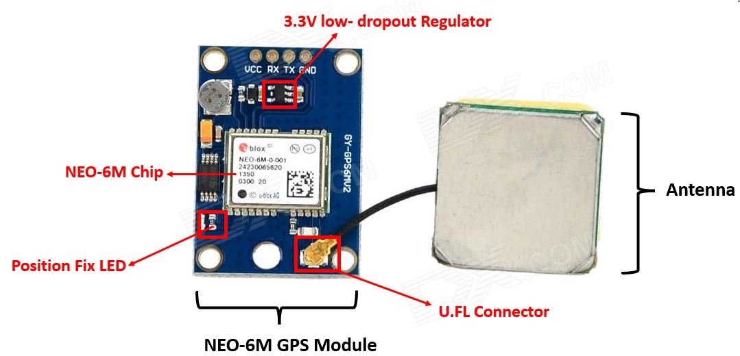
NEO-6M GPS Chip
In the middle of the GPS module, you can find the NEO-6M chip. This is responsible for tracking up to 22 satellites and any location on the Earth on several channels. Due to its highly sensitive tracking nature, it makes the NEO-6M module a popular GPS tracker.
Some key features of NEO-6M chip include:
- High sensitivity for tracking
- Low supply current (~45mA)
- Is able to track 5 locations per second with an accuracy of 2.5m (horizontal).
- Comes equipped with PSM also known as Power Saving Mode. This mode causes very less power consumption by turning the module ON/OFF according to the need.
- Great use as GPS trackers in smart watches due to very low power consumption (~11mA)
Position Fix LED Indicator
Moving ahead, the module comes with a position fix LED indicator. This LED indicates through its blinking effect whether the module is searching for satellites or has already found them. If the LED blinks after every second, then it indicates that the position fix is found. However, if the LED does not blink then the module is still searching for the satellites.
3.3V low-dropout Regulator
The module also comes equipped with a 3.3V LDO regulator (MIC5205). This provides an efficient linear voltage regulation with ultralow-noise output and very low dropout voltage. Additionally, the module is can also tolerate 5V easily so programming it with Arduino is very convenient.
Specifications
The table below shows some specifications of the NEO-6M module.
| Type | GPS |
| Supply | 2.7 V-3.6 V |
| Operating Current | 45mA |
| Operating Temperature | -40°C ~ 85°C |
| Horizontal Position Accuracy | 2.5m |
| Communication Protocol | NMEA, UBX Binary, RTCM |
| Features | RTC Crystal and External Interrupt/Wake up |
| Interface | UART, SPI, USB and DDC |
For more information regarding the NEO-6M module refer to its datasheet given here.
Pinout of NEO 6M Module
The diagram below shows the pinout of the NEO 6M module. It consists of 4 pins named GND, TX, RX, and VCC.
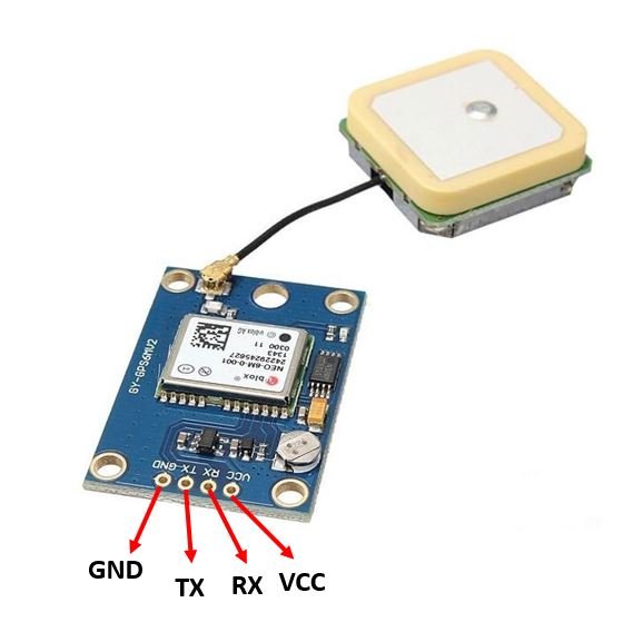
| GND | This is the ground pin that will be connected with the ground of the Arduino UNO. |
| TX | This is the transmission pin used for serial communication. |
| RX | This is the receiver pin used for serial communication. |
| VCC | This is the VCC pin used to power up the GPS module. Connect it with the 5V of the Arduino UNO board. |
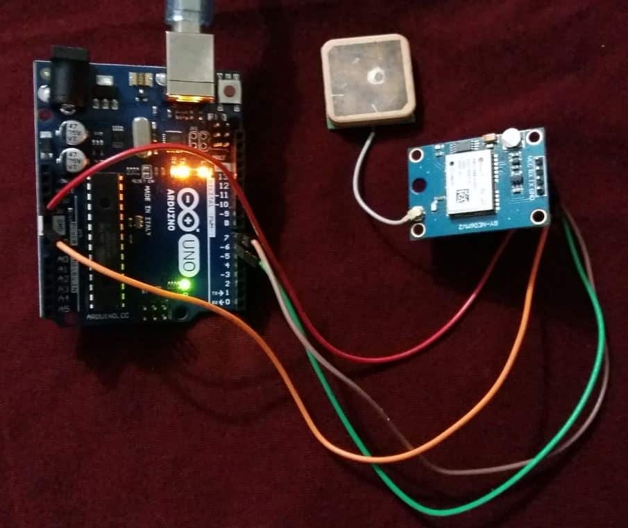
Connection of Arduino UNO and NEO-6M Module
The NEO-6M GPS module has 4 terminals which we will connect with the Arduino board. As the GPS module is 5V tolerant, hence we will connect the VCC terminal with 5V of the Arduino UNO. We will connect the TX (transmitter) terminal and the RX (receiver) terminal of the GPS module with the digital pins of the Arduino UNO. Software serial will be used for communicating between the two devices. Hence, we will set Pin 6 for TX and Pin 7 for RX in the program sketches. Therefore, TX of NEO-6M will be connected with pin 7 and RX of NEO-6M will be connected with Pin 6. You can use any other digital pin as well. Additionally, both the devices will have their grounds in common.
| Arduino UNO | NEO-6M Module |
| 5V | VCC |
| 6 | TX |
| 7 | RX |
| GND | GND |
Schematic Diagram
Connect both the Arduino UNO and NEO-6M GPS module as shown below. We have used the same connections as mentioned in the table above.

Arduino Sketch: Obtaining GPS Data from NEO-6M Module
Open your Arduino IDE and go to File > New. A new file will open. Copy the code given below in that file and save it.
#include <SoftwareSerial.h>

int Rx_pin = 7;
int Tx_pin = 6;
SoftwareSerial SerialGPS(Rx_pin, Tx_pin);

void setup()
{
  Serial.begin(9600);
  SerialGPS.begin(9600);
}

void loop()
{
  while (SerialGPS.available() > 0)
  Serial.write(SerialGPS.read());
}
First, we are icluding the SoftwareSerial.h library as we will be using software serial to communicate between the two devices.
#include <SoftwareSerial.h>Then we will set up the RX and TX pins. These will be passed as a parameter inside the SoftwareSerial instance called SerialGPS().
int Rx_pin = 7;
int Tx_pin = 6;
SoftwareSerial SerialGPS(Rx_pin, Tx_pin);
Inside the setup() function, we will open the serial communication for both the Arduino port and the GPS port at a baud rate of 9600. The NEO-6M has a default baud rate of 9600 so we are using 9600.
void setup()
{
  Serial.begin(9600);
  SerialGPS.begin(9600);
}
Inside the loop() function, we will read the GPS port and print the data in the serial monitor.
void loop()
{
  while (SerialGPS.available() > 0)
  Serial.write(SerialGPS.read());
}
Demonstration
To see the demonstration of the above code, upload the code to Arduino UNO.
Make sure the antenna is securely fixed to the U.FL connector on the NEO-6M module.
Before uploading code, make sure to select the Arduino board from Tools > Board and also select the correct COM port to which the Arduino board is connected from Tools > Port.

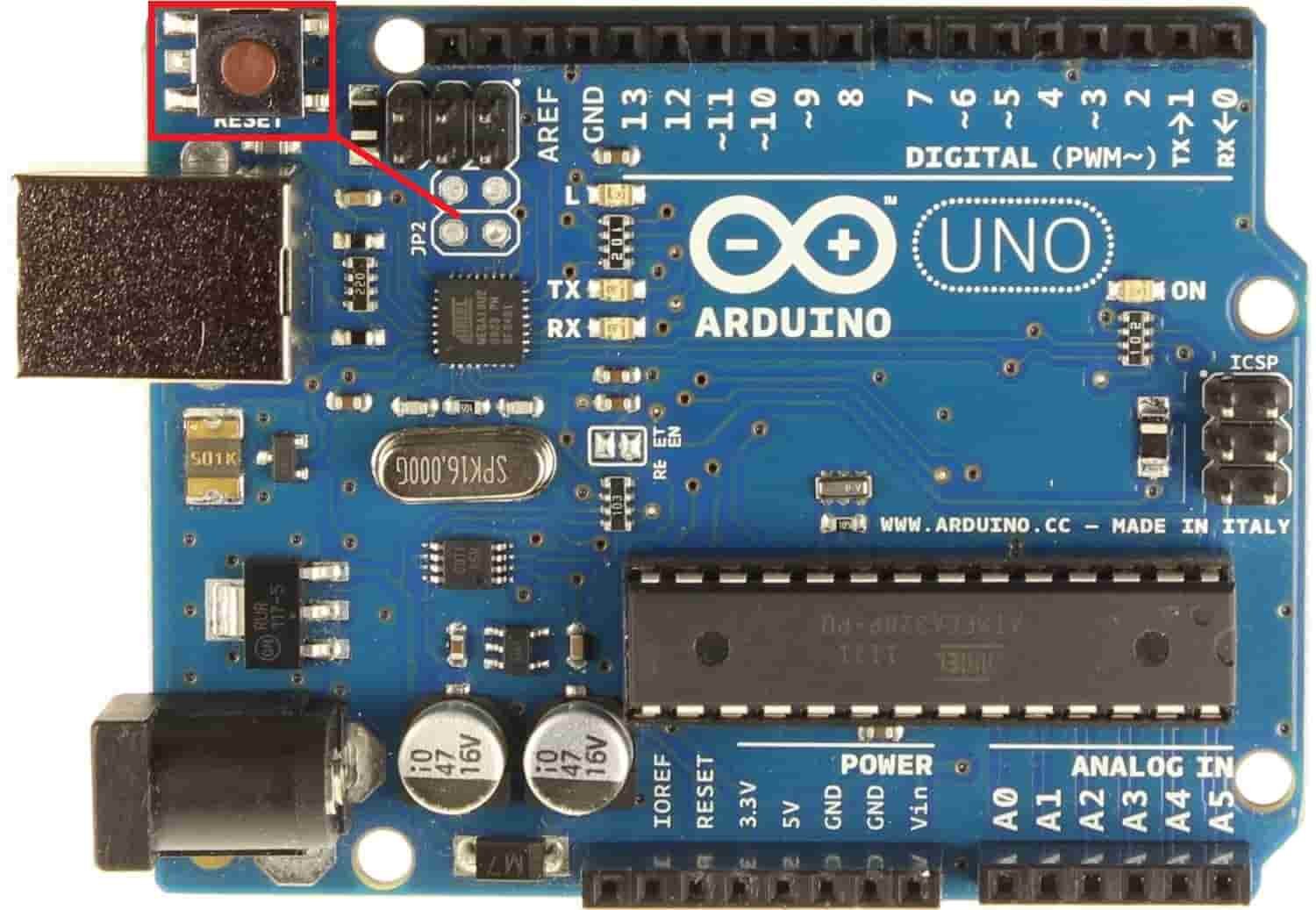
Once the code is uploaded to Arduino, open the serial monitor and set the baud rate to 9600. Press the RST button on the Arduino UNO.
Instantly, the serial monitor will start displaying the GPS data in NMEA sentences. It will look something like this:
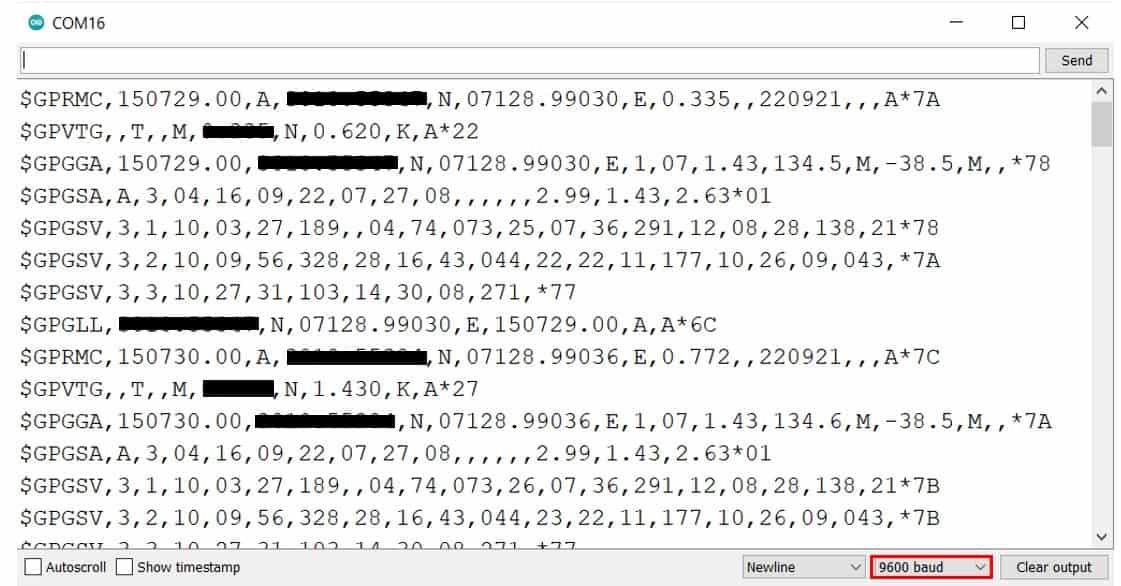
Understanding basic NMEA sentence
You will notice that the serial monitor is showing GPS data of various kinds including $GPRMC, $GPGGA etc. Each NMEA data field is separated by a comma and starts with a ‘$’.
Below you can view the $GPXXX syntax that denotes the different types of NMEA messages:
| $GPGGA | Global Positioning System Fix Data. It provides 3D location and accuracy data |
| $GPGSA | It provides GPS DOP and active satellites |
| $GPGSV | It provides the detailed information of the GPS satellite |
| $GPGLL | It provides the geographic Latitude and Longitude |
| $GPRMC | It provides the position, velocity and time |
| $GPVTG | It provides the dual ground/water speed |
Let us understand how to read the basic NMEA sentence i.e. $GPGGA. Here is an example $GPGGA NMEA sentence:
$GPGGA, 103005, 3807.038, N, 07128.99030, E, 1, 07, 1.43, 134.5, M, 42.9, M, , *78- $: This indicates the start of the NMEA sentence
- GPGGA : Global Positioning System Fix Data
- 103005 : This is the UTC time when the data was accessed in HH:MM:SS. In this case the time is 10:30:05 UTC
- 3807.038, N : Latitude 38 degrees 07.038′ N
- 07128.99030, E : Longitude 71 degrees 28.00030′ E
- 1 : GPS fix
- 07 : Number of satellites being tracked
- 1.43 : Horizontal dilution of position
- 134.5, M : This shows the altitude (m) above the sea level
- 42.9, M : Height of geoid (mean sea level)
- Empty field : time in seconds since last DGPS update
- Empty field : DGPS station ID number
- *78 : the checksum data
Using TinyGPS++ Library to parse NMEA data
We will use Arduino IDE to program our Arduino UNO. To program our Arduino UNO to parse NMEA messages easily we will be required to install TinyGPS++.h library.
Apart from the functions, we will use in the second sketch with TinyGPS++ that will help us access our location’s longitude, latitude, altitude as well as the current date and time, we also have some additional functions available by this library:
- gps.speed.value(): This function provides us with the current ground speed in 100ths of a knot.
- gps.course.value(): This function provides us with the current ground course in 100ths of a degree
- gps.hdop.value(): This function provides us with the horizontal dilution of precision (GPS)
- gps.satellites.value(): This function provides us with the number of satellites being tracked
- age(): This method returns the number of milliseconds passed since the last update
Installing TinyGPS++ Library
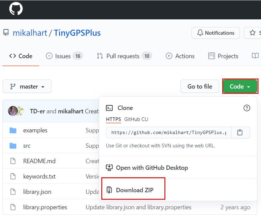
To make our project easier we will install the TinyGPS++ library to easily handle the receiving data from the GPS module. To download the library, click here. Click on ‘Code’ and then ‘Download Zip’.
You have to go to Sketch > Include Library > Add .zip Library inside the IDE to add the library as well.
Arduino Sketch with TinyGPS++ Library
Open your Arduino IDE and go to File > New. A new file will open. Copy the code given below in that file and save it.
This sketch will display the location’s latitude, longitude and altitude. Additionally, the current date and time will also be displayed in the serial monitor. This will be achieved through the functions of the TinyGPS++ librray that will easily parse through the NMEA message and display it in a easy convenient format.
#include <TinyGPS++.h>
#include <SoftwareSerial.h>

int RXPin = 7;
int TXPin = 6;

TinyGPSPlus gps;
SoftwareSerial SerialGPS(RXPin, TXPin);

void setup()
{
  Serial.begin(9600);
  SerialGPS.begin(9600);
}

void loop()
{
  while (SerialGPS.available() > 0)
    if (gps.encode(SerialGPS.read()))
      showData();
  if (millis() > 5000 && gps.charsProcessed() < 10)
  {
    Serial.println("GPS NOT DETECTED!");
    while(true);
  }
}

void showData()
{
  if (gps.location.isValid())
  {
    Serial.print("Latitude: ");
    Serial.println(gps.location.lat(), 6);
    Serial.print("Longitude: ");
    Serial.println(gps.location.lng(), 6);
    Serial.print("Altitude: ");
    Serial.println(gps.altitude.meters());
  }
  else
  {
    Serial.println("Location is not available");
  }

  Serial.print("Date: ");
  if (gps.date.isValid())
  {
    Serial.print(gps.date.month());
    Serial.print("/");
    Serial.print(gps.date.day());
    Serial.print("/");
    Serial.println(gps.date.year());
  }
  else
  {
    Serial.println("Not Available");
  }

  Serial.print("Time: ");
  if (gps.time.isValid())
  {
    if (gps.time.hour() < 10) Serial.print(F("0"));
    Serial.print(gps.time.hour());
    Serial.print(":");
    if (gps.time.minute() < 10) Serial.print(F("0"));
    Serial.print(gps.time.minute());
    Serial.print(":");
    if (gps.time.second() < 10) Serial.print(F("0"));
    Serial.print(gps.time.second());
    Serial.print(".");
    if (gps.time.centisecond() < 10) Serial.print(F("0"));
    Serial.println(gps.time.centisecond());
  }
  else
  {
    Serial.println("Not Available");
  }

  Serial.println();
  Serial.println();
  delay(5000);
}
How the Code Works?
Firstly, we will include the libraries which are required for this project. The TinyGPS++ library will be used to extract the useful GPS data whereas the SoftwareSerial library will be used as we are software serial to communicate between the two devices.
#include <TinyGPS++.h>
#include <SoftwareSerial.h>
Then we will set up the RX and TX pins. These will be passed as a parameter inside the SoftwareSerial instance called SerialGPS().
int RXPin = 7;
int TXPin = 6;

SoftwareSerial SerialGPS(RXPin, TXPin);
Additionaly, we will create a TinyGPSPlus object called ‘gps’ which we will use later on in the sketch to acquire the data.
TinyGPSPlus gps;Inside the setup() function, we will open the serial communication for both the Arduino port and the GPS port at a baud rate of 9600. The NEO-6M has a default baud rate of 9600 so we are using 9600.
void setup()
{
  Serial.begin(9600);
  SerialGPS.begin(9600);
}
Inside the loop() function, we will read the GPS data and then call the showData() function to display it appropriately in the serial monitor. Additionally, the serial monitor will also display “GPS NOT DETECTED!” message if there is no data aquired after 5000ms.
while (SerialGPS.available() > 0)
    if (gps.encode(SerialGPS.read()))
      showData();
  if (millis() > 5000 && gps.charsProcessed() < 10)
  {
    Serial.println("GPS NOT DETECTED!");
    while(true);
  }
The showData() function displays the latitude, longitude, and altitude for a valid location in the serial monitor. Moreover, the date and the current time is also displayed.
void showData()
{
  if (gps.location.isValid())
  {
    Serial.print("Latitude: ");
    Serial.println(gps.location.lat(), 6);
    Serial.print("Longitude: ");
    Serial.println(gps.location.lng(), 6);
    Serial.print("Altitude: ");
    Serial.println(gps.altitude.meters());
  }
  else
  {
    Serial.println("Location is not available");
  }

  Serial.print("Date: ");
  if (gps.date.isValid())
  {
    Serial.print(gps.date.month());
    Serial.print("/");
    Serial.print(gps.date.day());
    Serial.print("/");
    Serial.println(gps.date.year());
  }
  else
  {
    Serial.println("Not Available");
  }

  Serial.print("Time: ");
  if (gps.time.isValid())
  {
    if (gps.time.hour() < 10) Serial.print(F("0"));
    Serial.print(gps.time.hour());
    Serial.print(":");
    if (gps.time.minute() < 10) Serial.print(F("0"));
    Serial.print(gps.time.minute());
    Serial.print(":");
    if (gps.time.second() < 10) Serial.print(F("0"));
    Serial.print(gps.time.second());
    Serial.print(".");
    if (gps.time.centisecond() < 10) Serial.print(F("0"));
    Serial.println(gps.time.centisecond());
  }
  else
  {
    Serial.println("Not Available");
  }

  Serial.println();
  Serial.println();
  delay(5000);
}
Demonstration
To see the demonstration of the above code, upload the code to Arduino. But, before uploading code, make sure to select the Arduino board from Tools > Board and also select the correct COM port to which the Arduino board is connected from Tools > Port.
Once the code is uploaded to Arduino, open the serial monitor and set the baud rate to 9600. Instantly the serial monitor will start displaying the location parameters and the current date and time.

In the coming tutorial, we have planned to design a GPS data logger using Arduino and NEO-6M GPS module. In this data logger, we will store the GPS parameters into an SD card after a certain interval of time. Users can later use this data logger for various data analysis.
To read more GPS related articles, follow the links below:
Excellent code
Everything is working well except the altitude parameter that is always zero. some idea why?
Best regards
Dennis
Hello,
Beautiful work, but inconsistencies in the allocation of RX and TX pin.
In the document you specify 7 for TX and 6 for RX, but in the code, it is the opposite! ::
int Rx_pin = 7;
int Tx_pin = 6;
I can only advise you to correct!
Long life and take care of yourself.
Hi Pascal,
Thanks for pointing out a type. We have fixed it. Thanks
Hello, could you give me the formula to find the distance and azimuth between
two points with coordinates given by the gps neo, thanks in advance.