In this guide, we will learn about SG-90 servo motor and how to use them with Arduino UNO. Firstly, we will see an introduction of the servo motor. After that, we will look at how to interface it with Arduino and control its movement.
Movement of objects can be controlled by controlling motion of motors. Similarly in robotics, servo motor control mechanism is very useful to control position of robotics. Servo motor is a position controlled motor. It can easily control physical movement of objects due to its position controlled feature. Servo motor have many applications in robotics and industry for position based motion control system.
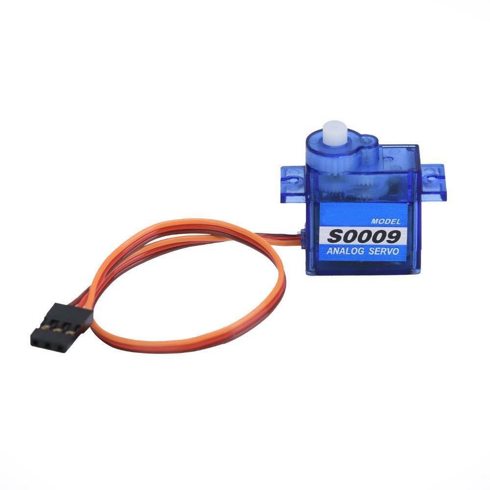
SG-90 Servo Motor
SG90 is a low cost and high output power servo motor. It can not move continuously but rotates up to 180 degrees and each step can be of maximum 90 degrees. Moreover, it is small enough that it can easily fit into your robotics ARM or obstacle avoidance robotics projects. On top of that, it requires only one output pulse signal to control its movement.

The following figure shows the pinout diagram of SG90 servo motor. It consists of three pins only such as PWM, ground and Vcc pin. Brown, orange and red wires are GND, Vcc and PWM pins respectively. Details and functionality of each pin is listed in the next section.
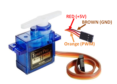
Pin Configuration Details
Vcc and ground, as their name suggests, are the power supply pins which are used to power servo motor. Only 5 volts of power signal is required to power this motor. Mostly microcontrollers or development boards have onboard 5 volts supply which we can use to power SG90 servos.
This table briefly describes all three pins:
| Wire of motor | Possible colors of each wire |
|---|---|
| Vcc pin | Red |
| GND pin | Black, or brown |
| Control Signal / PWM pin | Yellow, orange, or white |
Servo Motor Controller
Servo motors are very easy to interface with Arduino because they have built-in motor controllers. Servo motor consists of following parts or in other words complete servo motor package consists of following components :
- Gears are used to control position in degrees
- Output shaft is used to connect with physical objects
- Potentiometer is for position feedback
- Pulse to voltage converter is for feedback voltage to potentiometer
- H bridge is to control the position of motor (clock wise or anti clock wise)
- Comparator make with amplifier
Servo motor can not move with continuous motion unless feedback potentiometer is connected. H bridge is used to rotate motor either in clock wise or anti clock wise direction. So the main advantage of servo motor is that it doesn’t require any interfacing circuit. However, the main disadvantage of servo motor is its lower speed and low power limitation as compared to other motors.
Servo Motor Working
A servo motor responds to changes in duration of pulses. A pulse of duration 1 millisecond causes the servo motor to move one end and duration of 2 millisecond causes the motor to move other end. We can calculate the servo motor’s position by varying the duration of pulses to servo with the help of Arduino Uno R3. Fortunately Arduino IDE already has a built-in library (servo.h ) for servo motor control. So you don’t need to write lengthy code for servo motor. You just have to call a function used in servo.h library and its as simple as that.
How to control Servo motor rotator movement?
The position of the servo rotator is directly related with the width pulse applied to the PWM signal of the motor.
To control rotation, we apply pulses to the PWM pin of the servo motor. The frequency of the PWM signal should be 50Hz. That means the control signal pulse should be applied to the PWM pin every 20ms duration. The width of the pulse has a direct relation with the angular position of the motor.
For SG90 type servo motors, the pulse width of 1ms crossponds to 0-degree rotation, 1.5ms to 90 degree and 2ms to 180 degree rotation.
Hence, the pulse width between 1ms to 2ms controls the shaft position of the servo motor between 0 to 180 degrees.
Note: This pulse duration may be different for different types of servo motors.
Interfacing Servo Motor with Arduino
In this section, we will see how to interface a servo motor with Arduino.
Connection Diagram
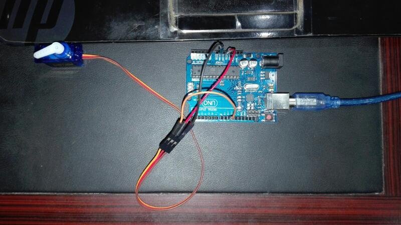
Servo motor control using Arduino Uno R3 can be easily done by interfacing servo motor with Arduino. Unlike other motors, servo motor is very easy to interface with Arduino or any other microcontroller due to its built-in controllers. We only need three pins to interface the servo motor with Arduino. Power pin, Ground pin and pulse signal pin.
Now make connections with Arduino and SG-90 servo motor according to this schematic diagram.
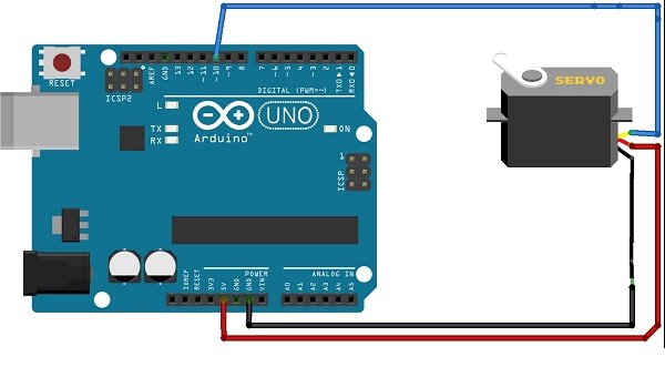
For the servo motor, we have connected the control signal pin with Arduino digital pin 10. The VCC and GND pins are in common with the Arduino 5V and GND pins. You can, however, use an external 5V power supply to power the servo motor as well.
Check the following circuit diagram for more clear view :

Arduino Sketch Controlling Servo Motor
Open your Arduino IDE and go to File > New. A new file will open. Copy the code given below in that file and save it.
This basic sketch will show us how to control a servo motor’s position with specific or calculated angle. The following code is written for calculated angle position control of servo motor using Arduino UNO with the Servo.h library.
#include<Servo.h>

Servo myloop; // create servo object to control a servo
int angle = 0; // variable to store the servo position
void setup()
{
  myloop.attach(10); // attached the servo on pin 10 to the servo object
}

void loop()
{
  for (angle = 0; angle < 180; angle += 1) // goes from 0 degrees to 180 degrees
  { // in steps of 1 degree
    myloop.write(angle); // tell servo to go to position in variable 'angle'
    delay(20); // waits 20ms between servo commands
  }
  for (angle = 180; angle >= 1; angle -= 1) // goes from 180 degrees to 0 degrees
  {
    myloop.write(angle); // move servo in opposite direction
    delay(20); // waits 20ms between servo commands
  }
}
How the Code Works?
Firstly we will include the built-in Servo.h library.
#include <Servo.h> Then we will create an object of this library called ‘myloop.’ This will be used to control the servo motor.
Servo myloop; // create servo object to control a servoThe ‘angle’ variable holds the current position of the servo motor’s arm. Initially we have set it to 0.
int angle = 0; // variable to store the servo positionInside the setup() function, we will attach digital pin10 with the servo object. Notice this is the Arduino pin that is connected with the PWM pin of the servo motor.
void setup()
{
  myloop.attach(10);
}
Inside the loop() function, we will move the servo motor’s arm clockwise and anti-clockwise using the write() method on the servo object. Here we are passing the ‘angle’ variable as a parameter inside this function. This will position the servo arm according to the values held in the angle variable that will first vary from 0-180 degrees and then 180 to 0 degrees by using a for loop.
void loop()
{
  for (angle = 0; angle < 180; angle += 1) // goes from 0 degrees to 180 degrees
  { // in steps of 1 degree
    myloop.write(angle); // tell servo to go to position in variable 'angle'
    delay(20); // waits 20ms between servo commands
  }
  for (angle = 180; angle >= 1; angle -= 1) // goes from 180 degrees to 0 degrees
  {
    myloop.write(angle); // move servo in opposite direction
    delay(20); // waits 20ms between servo commands
  }
}
Demonstration
To see the demonstration of the above code, upload the code to Arduino. Before uploading the code, make sure to select Arduino UNO from Tools > Board.

Also, select the correct COM port to which the Arduino board is connected from Tools > Port.
Once the code is uploaded to your board, the motor will start rotating.
Watch the video demonstration below:
You may also like to read:
- Web Controlled Servo Motor using Arduino and ESP8266
- Joystick Based Servo Motor Control using Arduino
- Servo Motor with Raspberry Pi Pico using MicroPython
- Interface MG995 Servo Motor with Arduino – Example Code
- CCPM Servo Consistency Master/Servo Motor Tester
- SG-90 Servo Motor Interfacing with TM4C123 Launchpad
- ESP32 Web Server Control Servo motor with Arduino IDE
what language do u use for this project?
what language do u use for this project?
what language do you use for this project?
what language do u use for this project
I need a Delta servo Drive