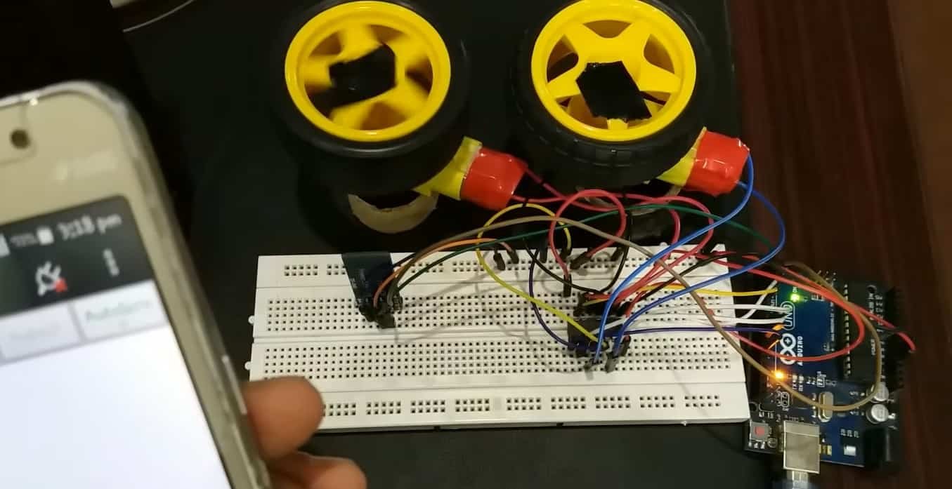
In this tutorial, you will learn how to control the speed and direction of a dc motor with Arduino using Bluetooth and Andriod application. We will use HC-05 Bluetooth module to establish the Bluetooth connection between Andriod app and Arduino. HC-05 Bluetooth will be used to communicate with Arduino using an Android Application known as the S2 Terminal. There are also other apps but this is free and easy to use. It is a very simple project where you will learn how to control the DC motor’s direction of rotation. The communication between the motors and the smartphone is done by using Bluetooth module HC-05, that attached to Arduino UNO.
In a previous article, we controlled the speed of the DC motor using a pic microcontroller. However, Bluetooth was not involved in that project. You may want to have a look at that as well:
In another tutorial, we learned how to control a DC motor’s speed and direction using the L293D motor driver IC with Arduino.

DC Motors Introduction
These motors are electro-mechanical machines which convert electrical energy into mechanical (rotational) energy. If you are looking to develop a robot such as a line follower robot, or obstacle avoidance robot, these DC motors will be the first choice for you. They are available in direct drive or geared types. But, both types require a dc voltage to operate. Therefore, we apply a DC voltage to drive DC motors.
DC Motor Speed Control
The speed of rotation of motors is directly related to the input voltage. The higher the input voltage, the higher will be the rotational speed of the motor. But the voltage should be within the operating voltage range.
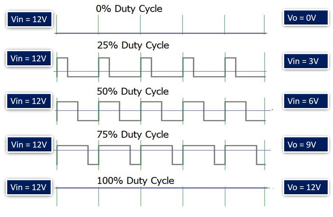
One important point to note here is that if we want to control the speed of a DC motor, we will need to provide a variable voltage to the DC motor. For example, If the operating voltage range of a motor is between 3 – 6 volts. If we apply 3 volts input, the motor will run at its lowest rated speed. Similarly, if we apply 6 volts, the DC motor will run at its highest rated speed. In short, we can control the speed of rotation by giving a variable input voltage to a DC motor. Usually, a pulse width modulation technique is used to generate a variable dc voltage from constant dc voltage source.
DC Motor Direction Control
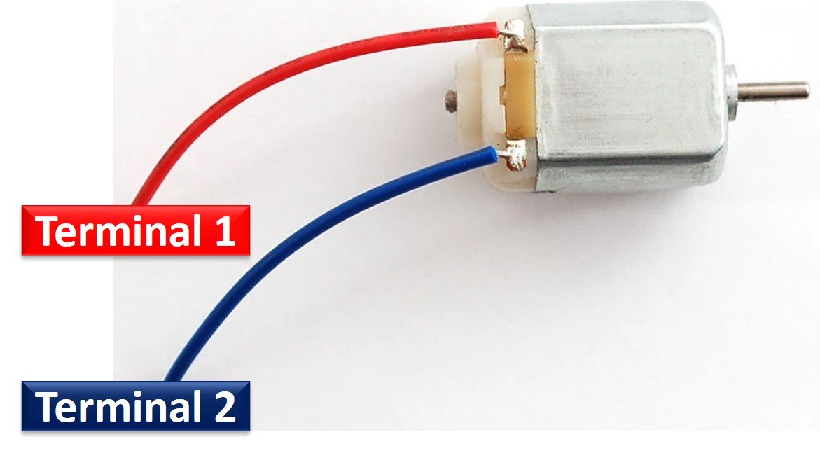
As you know that in case of DC power supply, there is a concept of polarity such as positive and negative terminals of a battery. The polarity of input voltage source determines the direction of rotation of a DC motor. For instance, if we connect the positive terminal of battery with one terminal and the negative terminal of battery with another terminal of DC motor, it will start rotating in clockwise direction. But if we interchange the connection of the battery by connecting opposite polarity, the DC motor will start rotating in another direction as shown in the simulation below.
Generally, an H-Bridge circuit is used to provide opposite polarity power to a DC motor without changing actual power supply connections. An H-Bridge consists of four switches, resistors, and two control signals as shown in the figure. Two logic probes control the direction of a DC motor. When left probe logic signal is on, the motor rotates in an anti-clockwise direction and when right probe logic signal is on, the motor rotates in a clockwise direction.

Control DC Motor using Arduino and Bluetooth Overview
We will require the following components for this project.
Required Components:
- Arduino Uno: We will use Arduino due to its simplicity and it also provides several digital pins to interface with the DC motor and the Bluetooth module at the same time. It is very useful when you prototyping a project.
- 2 DC Motors
- L293D Motor Driver IC: The L293D IC is a powerfully built motor driver IC. It is a dual-channel H bridge motor driver IC which can be easily used to drive two motors.
- HC-05 Bluetooth Module: HC-05 is one of the commonly used Bluetooth devices that uses UART communication protocol. It is a class-2 Bluetooth module with Serial Port Profile, which can configure as either Master or Slave. We can use it simply for a serial port replacement to establish a connection between MCU, PC to your embedded project and etc.
Let us first look at the details of L293D motor driver IC and HC-05 Bluetooth module before proceeding further.
L293D Motor Driver IC
L293D IC is known as a motor driver. It is a low voltage operating device like other ICs. L293D provides the continuous bidirectional Direct Current to the Motor. The Polarity of current can change at any time without affecting the whole IC or any other device in the circuit. L293D has an internal H-bridge installed for two motors.
H-Bridge is an electrical circuit that enables the load in a bidirectional way. L293D bridge is controlled by external low voltage signals. It may be small in size, but its power output capacity is higher than our expectation. It could control any DC motor speed and direction with a voltage range of 4.5 – 36 Volts. Its diodes also save the controlling device and IC from back EMF. To control the max 600mA amount of current an internal “Darlington transistor sink” installed in it, which could be used to control a large amount of current by providing a small amount of current. It has also internal “pseudo-Darlington source” which amplifies the input signal to control the high voltage DC motor without any interception.
Pinout
The diagram below shows the pin out of L293D IC:

Enable Pins
- Pin1 (Enable): Pin 1 is known as the enable pin. It has a major effect on Input and output. If there is High logical signal on enable pin (EN) then there will be input and output between pin 2,3,6 & 7 (Input 1, Output 1, Input 2 & Output 2)
- Pin9 (Enable): Pin 9 is also the same as Pin 1. It controls the input and output signals. Pin 9 Controls the connection between Input 3, Input 4, Output 3 and Output 4. It also enables the connection when the logic signal will be High (1).
Input Pins
- Pin2 (Input 1): Mostly input means where we provide the input to give the output. But here Input 1 means which polarity we want to give at Output 1.
- Pin7 (Input 2): Input 2 will attach to the control button or device to control the Output 2 just like Input 1.
- Pin10 (Input 3): Input 3 will control the output polarity of the Pin 11 (Output 3) by logic signals.
- Pin15 (Input 4): Pin 15 will control the output polarity of the Pin 14 (Output 4) by logic signals.
Output Pins
- Pin3 (Output 1): Output 1 is the input of the first motor/Motor 1. It attaches to its one end.
- Pin6 (Output 2): Output 2 will attach to the input of the first motor/Motor 1. It will attach to its second end.
- Pin11 (Output 3): Output 3 will be connected to the one end of the second motor.
- Pin14 (Output 4): Pin 14 will attach to the second end of the second motor.
Power Pins
- Pin8 (Vcc): Pin8 is the voltage pin for Motor. It will decide how much power we are going to attach the Motor. This Power should not be more than 36 volts and should not be less than 4.5 volts.
- Pin16 (Vcc): Pin 16 will the Power we will provide to the L293D to activate it or to turn it on. The power level of Pin 16 should be 4.5 – 7 Volts. Voltage more than 7 will burn the IC
- Pin4 (Ground) and Pin5 (Ground) : The ground pins will attach to the ground of the circuit.
- Pin12 (Ground) and Pin13 (Ground): These will attach to the common ground with all other grounds.
Control Pins
The L293D IC features both speed and direction control pins to control two motors simultaneously.
Direction Control Input Pins
The direction control pins are the four input pins (Pin2 IN1, Pin7 IN2, Pin10 IN3, Pin15 IN4) on the IC.
Through these input pins we can determine whether to move the dc motor forward or backwards. IN1 and IN2 control motor A’s spinning direction whereas IN3 and IN4 control motor B’s spinning direction. The table below shows the logic signals required for the appropriate spinning action for motor A.
| IN1 | IN2 | Motor Action |
|---|---|---|
| 1 (HIGH) | 1 | OFF |
| 1 | 0 (LOW) | Backward |
| 0 | 1 | Forward |
| 0 | 0 | OFF |
As seen from the table, whenever one of the inputs is in a HIGH state (5V) then the motor will spin. Otherwise, when both the inputs are LOW (ground) state or both are in HIGH state then the motor stops. In order for motor A to spin forward, IN1 should be LOW and IN2 should be HIGH. For backwards motion, IN1 should be HIGH and IN2 should be LOW. Motor B is also controlled in a similar way.
Speed Control Pins
The speed control pins pin1 (EN1,2 or ENA) and pin 9 (EN3,4 or ENB) on the IC, control the speed of the dc motor and turn it ON and OFF.
EN1,2 controls the speed of one motor and EN3,4 controls the speed of the other motor. If both of the pins are in a logic HIGH (5V) state, then both the motors are ON and spinning at maximum speed. If both of the pins are in a logic LOW (ground) state, then both the motors are OFF. Through the PWM functionality, we can also control the speed of the motor.
You can know more about the L293D motor drivers here:
Features
- L293D could be used to control the two motors at the same time.
- It has the ability to control the speed by using the enable pin.
- The direction is also easy to change.
- Voltage supply range is higher than other IC. Voltage range between 4.5-36 volts can easily handle by the IC to the motor.
- The motor has a maximum continuous range of current close to 600mA but the maximum peak current range is 1.2A
- It has an automatic shutdown system on thermal condition.
- Its working range is from 0 – 70 degree which is much higher for any small-sized IC.
- It has an internal back emp protection for IC and the controlling device.
HC-05 Introduction
HC-05 is one of the commonly used Bluetooth device that uses a UART communication protocol. The HC-05 Bluetooth is much different in features from all other Bluetooth devices because of its multiple pins and their functions. It has multiple pins for the different method which makes it unique as compared to others. The module normally operates at UART serial communication with TX and RX pins at 9600 baud rates. However, it can be programmed with AT commands and it supports 9600,19200,38400,57600,115200,230400,460800 baud rates.
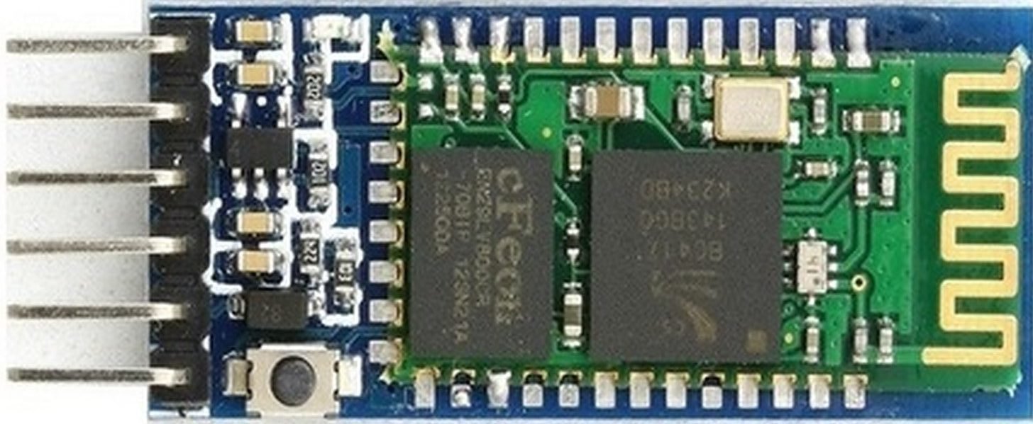
Its CSR Bluecore 04-External single chip is already configured to communicate with other Bluetooth devices through serial communication. It offers a two-way communication method and the HC-05 can act as either slave and master. The Bluetooth module offers only short distance communications due to its limitation but still, most of the devices come with it due to its speed and security. The limitation of this device is that it doesn’t allow to transfer any kind of media.
In short, this module can be used to perform low-cost wireless communication between microcontrollers such as Arduino, TM4C123, Pic Microcontroller, Raspberry Pi, BeagleBone, STM32, and Arduino Mega, etc. Also, we can use it for communication between a microcontroller and PC or Android application. There are many Android applications available in the Google Play store which we can use to send and receive data to/from HC05. For this tutorial, we will use ‘Serial Bluetooth Terminal’ application that we installed previously.
Recommended Reading: HC-05 Bluetooth Module
Pinout
The HC-05 comes with multiple pins and indicators, which helps to control different operations and view their states through indicators. This pinout diagram provides indications of all pins.
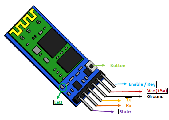
The table below also briefly describes the functionality of each pin.
| Pin | Description |
| VCC | The operating voltage range is 3.3 volts. But I/O pins can withstand voltage of up to 5 volts. Therefore, we can connect 5 volts power source to this pin, and also other pins can also operate on 5 volts signals such as Tx and Rx signals. |
| GND | Ground reference of both ESP8266 and HC-05 should be at the same level. Therefore, we should connect a power supply, HC05, and ESP8266 ground pins to each other. |
| Tx | As discussed earlier, the HC-05 Bluetooth module uses UART communication to transmit data. This is a transmitter pin. The TX pin will be the data transfer pin of the module in UART. |
| Rx | This pin is a data receiving the pin in UART communication. It is used to receive data from the microcontroller and transmits it through Bluetooth. |
| State | The state shows the current state of the Bluetooth. It gives feedback to the controller about the connectivity of Bluetooth with another device. This pin has an internal connection with the onboard LED which shows the working of HC05. |
| Enable/Key | Using an external signal, Enable/Key pin is used to change the HC-05 mode between data mode and command mode. The HIGH logic input will transfer the device in command mode and the LOW logic input will change the mode to data mode. By default, it works in data mode. |
| Button | The command and data mode states are changeable through a button present on the module. |
| LED | This pin shows the working status of module along with the State pin |
Control DC Motors using L293D Motor Driver IC and HC-05 with Arduino
Now, as we have learnt about the motor driver IC and the Bluetooth module, let us do a demonstration by showing you how to control two DC motors using this setup.
Required Equipment
- Arduino
- L283D Motor driver IC
- 2 DC Motors
- HC-05 Bluetooth Module
- Breadboard
- Connecting Wires
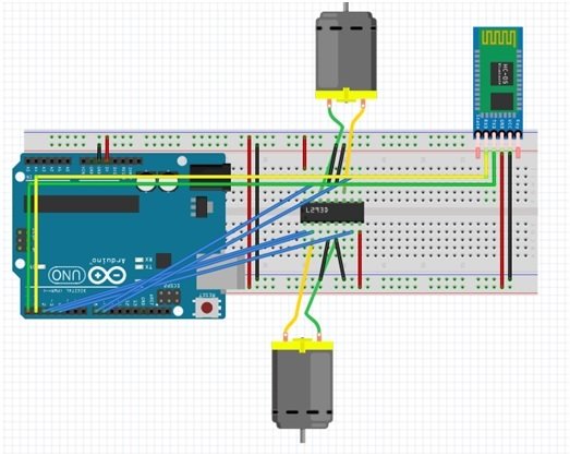
We are using TT DC gear motors for this project. They require an operating voltage of 3-12V DC where the recommended operating voltage is 3-6V DC. Connect 5V pin of Arduino with pin 8 of L293D IC and GND with common ground.
L293D IC with Arduino Connections
Then, we have connected the input pins Pin2 (IN1), Pin7 (IN2), Pin10 (IN3) and Pin15 (IN4) with digital pins of the Arduino UNO. We have used Arduino pin 3, 4, 8 and 9 respectively to connect with each of the input pins of the motor driver IC.
The enable pins pin1 (ENA) and pin9 (ENB) are connected with the digital PWM pins of the Arduino UNO board. We have used Arduino Pin 2 to connect with EN1,2 and Arduino Pin 11 with EN3,4.
Each of the motor’s terminal is connected at Pin3 (OUT1), Pin6 (OUT2) for one motor and Pin11 (OUT3), Pin14 (OUT4) for the second motor respectively.
Connect pin16 of the driver IC with 5V from Arduino.
HC-05 with Arduino Connections
- Connect VCC pin of Bluetooth module to 5 volts Arduino pin.
- Connect GND to Ground.
- Module Rx to Arduino Tx.
- Module Tx to Arduino Rx.
Additionally, all grounds should be common between all the devices.
Controlling DC Motor Speed and Direction using L293D Motor Driver IC and HC-05 Bluetooth Module
Throughout this guide, we will use an android smartphone that will connect to our Arduino development board. So, make sure you have an android phone at hand. We will also use a Bluetooth terminal application to pair the two devices together.
Go to the Play Store and download the application by the name: S2 Terminal.
Open the application and connect to the Bluetooth module. Write the specified commands and send it. Bluetooth module receives them and the Arduino performs the operation by controlling the DC motor’s direction of rotation.
The table below shows the commands that we will send by our mobile on the Bluetooth application and the response that will be received.
| Command sent by mobile | Function |
| 1 | Motor moves forward |
| 2 | Motor turns left |
| 3 | Motor stops |
| 4 | Motor turns right |
| 5 | Motor reverses |
Arduino Sketch
Open your Arduino IDE and go to File > New. A new file will open. Copy the code given below in that file and save it.
int motor1Pin1 = 3; // pin 2 on IC
int motor1Pin2 = 4; // pin 7 on IC
int enable1Pin = 2; // pin 1 on IC
int motor2Pin1 = 8; // pin 10 on IC
int motor2Pin2 = 9; // pin 15 on IC
int enable2Pin = 11; // pin 9 on IC

int state;
int flag = 0;
int stateStop = 0;

void setup() {

  // sets the pins as outputs:
  pinMode(motor1Pin1, OUTPUT);
  pinMode(motor1Pin2, OUTPUT);
  pinMode(enable1Pin, OUTPUT);
  pinMode(motor2Pin1, OUTPUT);
  pinMode(motor2Pin2, OUTPUT);
  pinMode(enable2Pin, OUTPUT);

  // sets enable1Pin and enable2Pin high so that motor can turn on:
  digitalWrite(enable1Pin, HIGH);
  digitalWrite(enable2Pin, HIGH);

  // initialize serial communication at 9600 bits per second:
  Serial.begin(9600);
}

void loop() {

  //Start Serial Communication
  if (Serial.available() > 0) {
    state = Serial.read();
    flag = 0;
  }

  // if the state is '1' the DC motor will go forward
  if (state == '1') {
    digitalWrite(motor1Pin1, HIGH);
    digitalWrite(motor1Pin2, HIGH);
    digitalWrite(motor2Pin1, LOW);
    digitalWrite(motor2Pin2, HIGH);

    if (flag == 0) {
      Serial.println("Go Forward!");
      flag = 1;
    }
    delay(3000);
    state = 3;
    stateStop = 1;
  }

  // if the state is '2' the motor will turn left
  else if (state == '2') {
    digitalWrite(motor1Pin1, HIGH);
    digitalWrite(motor1Pin2, LOW);
    digitalWrite(motor2Pin1, LOW);
    digitalWrite(motor2Pin2, LOW);

    if (flag == 0) {
      Serial.println("Turn LEFT");
      flag = 1;
    }
    delay(3000);
    state = 3;
    stateStop = 1;
  }

  // if the state is '3' the motor will Stop
  else if (state == '3' || stateStop == 1) {
    digitalWrite(motor1Pin1, LOW);
    digitalWrite(motor1Pin2, LOW);
    digitalWrite(motor2Pin1, LOW);
    digitalWrite(motor2Pin2, LOW);

    if (flag == 0) {
      Serial.println("STOP!");
      flag = 1;
    }
    stateStop = 0;
  }

  // if the state is '4' the motor will turn right
  else if (state == '4') {
    digitalWrite(motor1Pin1, LOW);
    digitalWrite(motor1Pin2, LOW);
    digitalWrite(motor2Pin1, LOW);
    digitalWrite(motor2Pin2, HIGH);

    if (flag == 0) {
      Serial.println("Turn RIGHT");
      flag = 1;
    }

    delay(3000);
    state = 3;
    stateStop = 1;
  }

  // if the state is '5' the motor will Reverse
  else if (state == '5') {
    digitalWrite(motor1Pin1, LOW);
    digitalWrite(motor1Pin2, HIGH);
    digitalWrite(motor2Pin1, HIGH);
    digitalWrite(motor2Pin2, LOW);

    if (flag == 0) {
      Serial.println("Reverse!");
      flag = 1;
    }

    delay(3000);
    state = 3;
    stateStop = 1;
  }
}
How the Code Works?
Firstly, we will define the L293D motor driver IC’s control pins connection with the Arduino UNO board. We have used the same pins as shown in the connection diagram above. Make sure the enable pins are connected with PWM enabled pins of the Arduino board. For the input pins you can use any digital pin of the Arduino UNO board.
int motor1Pin1 = 3; // pin 2 on IC
int motor1Pin2 = 4; // pin 7 on IC
int enable1Pin = 2; // pin 1 on IC
int motor2Pin1 = 8; // pin 10 on IC
int motor2Pin2 = 9; // pin 15 on IC
int enable2Pin = 11; // pin 9 on IC
Next we will declare some int variables that will be used later on in the code to monitor the movement.
int state;
int flag = 0;
int stateStop = 0;
setup()
Inside the setup() function, first we will configure all the control pins as output pins. This will be done by using the pinMode() function. The pin will be passed as the first parameter and OUTPUT will be passed as the second parameter.
  pinMode(motor1Pin1, OUTPUT);
  pinMode(motor1Pin2, OUTPUT);
  pinMode(enable1Pin, OUTPUT);
  pinMode(motor2Pin1, OUTPUT);
  pinMode(motor2Pin2, OUTPUT);
  pinMode(enable2Pin, OUTPUT);
Then by using the digitalWrite() function we will set up the enable pins to a HIGH state so that both the motors can turn on.
  digitalWrite(enable1Pin, HIGH);
  digitalWrite(enable2Pin, HIGH);
Moreover, open the serial communication at a baud rate of 9600.
Serial.begin(9600);loop()
Inside the loop() function we first start the serial communication. If the serial data is available in the buffer then it will get stored in the int variable ‘state’. Also, the int variable ‘flag’ will be set to 0.
  if (Serial.available() > 0) {
    state = Serial.read();
    flag = 0;
  }
Controlling DC Motor Direction
Now we will use a series of if else-if statements to check which command was sent and appropriately control the movement of the DC motors. This is done by providing the input pins (IN1, IN2, IN3 and IN4) with different logic signals as stated in the table previously. Follow the table given in the Direction Control Pins section to set the input pins to required states appropriately.
Forward
If ‘1’ command is sent then the dc motor will move forwards. Moreover, if the ‘flag’ variable is set to 0 then the serial monitor will display “Go Forward!” and the ‘flag’ will be set to 1. Moreover, after a delay of a few seconds, the variable ‘state’ will be set to 3 and ‘stateStop’ will be set to 1.
  if (state == '1') {
    digitalWrite(motor1Pin1, HIGH);
    digitalWrite(motor1Pin2, HIGH);
    digitalWrite(motor2Pin1, LOW);
    digitalWrite(motor2Pin2, HIGH);

    if (flag == 0) {
      Serial.println("Go Forward!");
      flag = 1;
    }
    delay(3000);
    state = 3;
    stateStop = 1;
  }
Left
Otherwise if ‘2’ command is sent then the dc motor will move towards the left. Moreover, if the ‘flag’ variable is set to 0 then the serial monitor will display “Turn LEFT” and the ‘flag’ will be set to 1. Moreover, after a delay of a few seconds, the variable ‘state’ will be set to 3 and ‘stateStop’ will be set to 1.
  else if (state == '2') {
    digitalWrite(motor1Pin1, HIGH);
    digitalWrite(motor1Pin2, LOW);
    digitalWrite(motor2Pin1, LOW);
    digitalWrite(motor2Pin2, LOW);

    if (flag == 0) {
      Serial.println("Turn LEFT");
      flag = 1;
    }
    delay(3000);
    state = 3;
    stateStop = 1;
  }
Stop
Otherwise if ‘3’ command is sent or the ‘stateStop’ variable is 1, then the dc motor will stop. Moreover, if the ‘flag’ variable is set to 0 then the serial monitor will display “STOP!” and the ‘flag’ will be set to 1. The ‘stateStop’ will be set to 0.
  else if (state == '3' || stateStop == 1) {
    digitalWrite(motor1Pin1, LOW);
    digitalWrite(motor1Pin2, LOW);
    digitalWrite(motor2Pin1, LOW);
    digitalWrite(motor2Pin2, LOW);

    if (flag == 0) {
      Serial.println("STOP!");
      flag = 1;
    }
    stateStop = 0;
  }
Right
Otherwise if ‘4’ command is sent then the dc motor will move towards the right. Moreover, if the ‘flag’ variable is set to 0 then the serial monitor will display “Turn RIGHT” and the ‘flag’ will be set to 1. Moreover, after a delay of a few seconds, the variable ‘state’ will be set to 3 and ‘stateStop’ will be set to 1.
  else if (state == '4') {
    digitalWrite(motor1Pin1, LOW);
    digitalWrite(motor1Pin2, LOW);
    digitalWrite(motor2Pin1, LOW);
    digitalWrite(motor2Pin2, HIGH);

    if (flag == 0) {
      Serial.println("Turn RIGHT");
      flag = 1;
    }

    delay(3000);
    state = 3;
    stateStop = 1;
  }
Reverse
Otherwise if ‘5’ command is sent then the dc motor will move backwards. Moreover, if the ‘flag’ variable is set to 0 then the serial monitor will display “Reverse!” and the ‘flag’ will be set to 1. Moreover, after a delay of a few seconds, the variable ‘state’ will be set to 3 and ‘stateStop’ will be set to 1.
  // if the state is '5' the motor will Reverse
  else if (state == '5') {
    digitalWrite(motor1Pin1, LOW);
    digitalWrite(motor1Pin2, HIGH);
    digitalWrite(motor2Pin1, HIGH);
    digitalWrite(motor2Pin2, LOW);

    if (flag == 0) {
      Serial.println("Reverse!");
      flag = 1;
    }

    delay(3000);
    state = 3;
    stateStop = 1;
  }
}
Demonstration
To see the demonstration of the above code, upload the code to Arduino. Before uploading the code, make sure to select Arduino UNO from Tools > Board.

Also, select the correct COM port to which the Arduino board is connected from Tools > Port.
After you have uploaded your code to the development board, open the Bluetooth application and secure a connection between the devices. Now type an appropriate command and the motors will start moving accordingly.
Watch the video below:
You may also like to read:
- Control DC Motor using L298N Driver with Raspberry Pi Pico and MicroPython
- Interface L298N DC Motor Driver Module with ESP32
- ESP8266 NodeMCU Web Server Control DC Motor Speed
- Interface L298N DC Motor Driver Module with ESP8266 NodeMCU
- DC Motor Speed and Direction Control with TM4C123 and L298N Motor Driver
- Interface L298N DC Motor Driver Module with Arduino
- dc motor control with labview and Arduino
How to change the code to make:
motor 1: clockwise direction;
motor2: counterclockwise direction;
enable pwm to control speed of both motors at the same time? via bluetooth of course.
Best regards
Piter
How is it possible to use pin 4 of L293D IC as motor pin? Pins 4, 5, 12 & 13 of L293D IC are ground pins.
how can i see the diagram/schematic. what was the command you used on the phone to turn the both DC motor?