In this ESP8266 NodeMCU web server project, we will create a web page hosted on NodeMCU which we will use to control speed of a DC motor using the L298N motor driver module. A web page will consist of an HTML slider that will be used to generate variable duty cycle PWM for a DC motor. The slider will be moved to set duty cycle value. In response, this slider value will set the value of the PWM signal generated by ESP8266 NodeMCU. In short, this variable duty cycle PWM will control the speed of the DC motor.

Previously, we controlled the brightness of an LED connected with ESP8266 GPIO pin through the slider web server. You can view it below:
- In a previous article, we also built an ESP32/ESP8266 slider web server. We used the slider to control the onboard LED of the ESP board and turned it ON for a certain number of seconds. We will use the same method to create the slider as we did in that user guide. You can have a look at that article as well:
ESP32/ESP8266 Web Server to Control Outputs with a Timer (Pulse Width)
- Moreover, you can also go through the recommended reading given below. It is a useful MicroPython guide in which we used L298N motor driver along with ESP8266 to control the speed and direction of a DC motor. We will be using a similar approach in this guide as well but will program our ESP8266 board using Arduino IDE and include a web server with slider instead to control the speed.
Recommended Reading: MicroPython Control a DC Motor using L298N Driver with ESP32 and ESP8266
ESP8266 DC Motor Control Web Server Overview
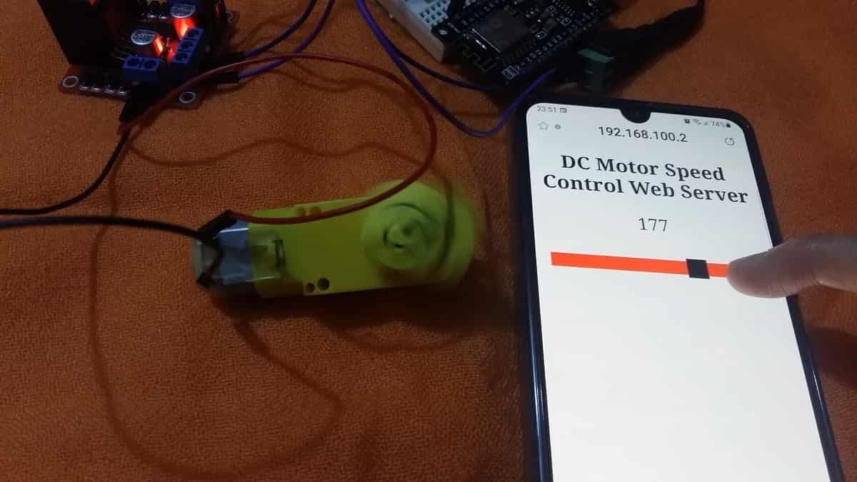
We will create an ESP8266 web server based on a slider that will be used to control the speed of a DC motor. The web server will consist of a title, “DC Motor Speed Control Web Server,” a slider to set the value that will set the PWM value and the slider value.

We will start by uploading our Arduino sketch to our ESP8266 board. In our serial monitor, we will obtain the IP address of our module that will help us access the web server. Copy that IP address in a web browser and press enter. The web server will be displayed.
Now we will move the slider to set the PWM value. This will generate an HTTP request with the slider value to our ESP8266 board. The slider value will also update to a new one as we move the slider. In our program sketch, we will set the slider value range between 0-255 as we will be using 8-bit resolution for optimization. You can set your own range as well. Hence, the slider can take a minimum value of 0 (motor stop) and a maximum of 255 (maximum speed of motor). When the ESP8266 receives the slider value, this value is used to set the PWM signal at the enable pin. Thus the slider will be used to control the speed of the DC motor where the increasing values increase the speed.
Note: The speed control pins labelled ENA and ENB on the module, control the speed of the dc motor via the PWM signal
Required Components
For this project we will require the following components:
- ESP8266 NodeMCU board
- L298N Motor Driver
- One DC Motor
- Connecting wires
- External 3-12 V power supply
ESP8266 DC Motor Speed Control Web Server Schematic Diagram
Assemble the circuit as shown in the connection diagram below.
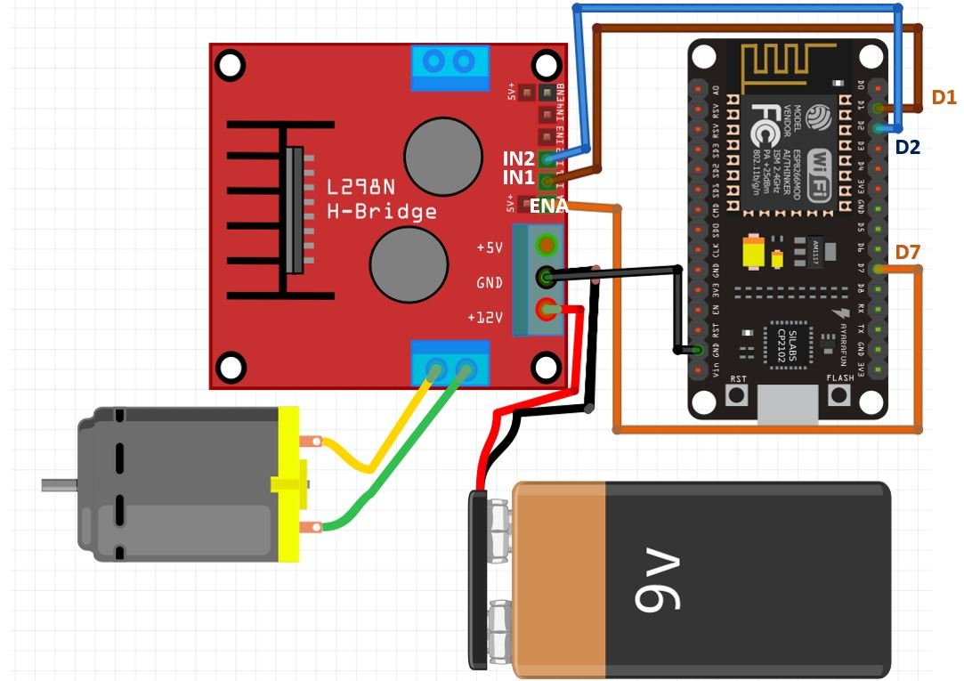
We will be using motor A output pins to control this motor. Thus, ENA will set the speed and IN1 and IN2 will set the spinning direction of the motor.
In ESP8266, PWM is supported through all input output GPIO pins. So choose any GPIO pin (GPIO0-GPIO16) to connect with the enable pin of the L298N motor driver. We have used D7 as the PWM pin. In the above schematic, we can see that D7 is connected with ENA, and IN1 and IN2 are connected with D1 and D2 respectively.
You can choose appropriate GPIO pins when connecting the ESP board and the driver module together.
The dc motor is rated at 6-12V, and requires a large amount of current to start. This is why we will be using an external power source for the dc motor. As we can use any power source ranging from 6-12V, we will incorporate a 9V battery in our case. You can use any other power source.
You can also read this in-depth guide:
Setting up Arduino IDE for ESP8266 PWM Slider Web Server
We will use Arduino IDE to program our ESP8266 development board. Thus, you should have the latest version of Arduino IDE. Additionally, you also need to install the ESP8266 plugin. You can visit the link shown below to have a look.
Installing ESPAsyncWebServer Library and ESPAsync TCP Library
We will need two libraries to build our ESP8266 web server.
- ESPAsyncWebServer
- ESPAsync TCP
The ESPAsyncWebServer library will help us in creating our web server easily. With this library, we will set up an asynchronous HTTP server. ESPAsync TCP library will also be incorporated as it a dependency for the ESPAsyncWebServer library. All of these libraries are not available in the Arduino library manager. Therefore, we will have to download and load them on our ESP8266 board ourselves.
- To install the ESPAsyncWebServer library for free, click here to download. You will download the library as a .zip folder which you will extract and rename as ‘ESPAsyncWebServer.’ Then, transfer this folder to the installation library folder in your Arduino IDE.
- To install the ESPAsync TCP library for free, click here to download. You will download the library as a .zip folder which you will extract and rename as ‘ESPAsyncTCP.’ Then, transfer this folder to the installation library folder in your Arduino IDE.
Likewise, you can also go to Sketch > Include Library > Add .zip Library inside the IDE to add the libraries as well. After installation of the libraries, restart your IDE.
You can read about ESP8266 asynchronous webserver here:
Arduino Sketch : ESP8266 PWM Slider Web Server
Open your Arduino IDE and go to File > New. A new file will open. Copy the code given below in that file and save it.
Remember to replace the network credentials.
#include <ESP8266WiFi.h>
#include <ESPAsyncTCP.h>
#include <ESPAsyncWebServer.h>

const char* ssid = "Your_SSID";
const char* password = "Your_Password";

int ENA_pin = D7;
int IN1 = D1;
int IN2 = D2;
String slider_value = "0";

const char* input_parameter = "value";

AsyncWebServer server(80);

const char index_html[] PROGMEM = R"rawliteral(
<!DOCTYPE HTML><html>
<head>
  <meta name="viewport" content="width=device-width, initial-scale=1">
  <title>DC Motor Speed Control Web Server</title>
  <style>
    html {font-family: Times New Roman; display: inline-block; text-align: center;}
    h2 {font-size: 2.3rem;}
    p {font-size: 2.0rem;}
    body {max-width: 400px; margin:0px auto; padding-bottom: 25px;}
    .slider { -webkit-appearance: none; margin: 14px; width: 360px; height: 25px; background: #FF0000;
      outline: none; -webkit-transition: .2s; transition: opacity .2s;}
    .slider::-webkit-slider-thumb {-webkit-appearance: none; appearance: none; width: 35px; height: 35px; background:#01070a; cursor: pointer;}
    .slider::-moz-range-thumb { width: 35px; height: 35px; background: #01070a; cursor: pointer; }
  </style>
</head>
<body>
  <h2>DC Motor Speed Control Web Server</h2>
  <p><span id="textslider_value">%SLIDERVALUE%</span></p>
  <p><input type="range" onchange="updateSliderPWM(this)" id="pwmSlider" min="0" max="255" value="%SLIDERVALUE%" step="1" class="slider"></p>
<script>
function updateSliderPWM(element) {
  var slider_value = document.getElementById("pwmSlider").value;
  document.getElementById("textslider_value").innerHTML = slider_value;
  console.log(slider_value);
  var xhr = new XMLHttpRequest();
  xhr.open("GET", "/slider?value="+slider_value, true);
  xhr.send();
}
</script>
</body>
</html>
)rawliteral";

String processor(const String& var){
  if (var == "SLIDERVALUE"){
    return slider_value;
  }
  return String();
}

void setup(){
  Serial.begin(115200);
  delay(1000);
  pinMode(ENA_pin, OUTPUT);
  pinMode(IN1, OUTPUT);
  pinMode(IN2, OUTPUT);

  analogWrite(ENA_pin, slider_value.toInt());
  digitalWrite(IN1, LOW);
  digitalWrite(IN2, LOW);

  WiFi.begin(ssid, password);
  while (WiFi.status() != WL_CONNECTED) {
    delay(1000);
    Serial.println("Connecting...");
  }

  Serial.println(WiFi.localIP());

  server.on("/", HTTP_GET, [](AsyncWebServerRequest *request){
    request->send_P(200, "text/html", index_html, processor);
  });

  server.on("/slider", HTTP_GET, [] (AsyncWebServerRequest *request) {
    String message;
    if (request->hasParam(input_parameter)) {
      message = request->getParam(input_parameter)->value();
      slider_value = message;
      analogWrite(ENA_pin, slider_value.toInt());
        digitalWrite(IN1, HIGH);
        digitalWrite(IN2, LOW);
    }
    else {
      message = "No message sent";
    }
    Serial.println(message);
    request->send(200, "text/plain", "OK");
  });

  server.begin();
}

void loop() {

}
How the Code Works?
Including Libraries
Firstly, we will include all the necessary libraries which are required for this project. ESP8266WiFi.h will help in establishing the connection between our ESP8266 module to a wireless network. We will also include the libraries which we installed previously, the ESPAsyncWebServer library, and the ESPAsyncTCP to build the ESP8266 asynchronous web server.
#include <ESP8266WiFi.h>
#include <ESPAsyncTCP.h>
#include <ESPAsyncWebServer.h>
Setting Network Credentials
Next, we will create two global variables, one for the SSID and the other for the password. These will hold our network credentials which will be used to connect to our wireless network. Replace both of them with your credentials to ensure a successful connection.
const char* ssid = "Your_SSID";
const char* password = "Your_Password";
Defining Control Pins
Next, we will define the L298N motor driver’s control pins connection with the ESP8266 board. We have used the same pins as shown in the connection diagram above. Make sure the enable pin is connected with PWM enabled pin of the ESP8266 board. For the input pins, you can use any appropriate GPIO pin of ESP8266.
int ENA_pin = D7;
int IN1 = D1;
int IN2 = D2;
Defining Slider Value
We will also define the slider value in a string value and set it to 0. Thus, initially when the web server will load you will see 0 as the slider value.
String slider_value = "0";Setting Input Parameter
We will pass another global variable of type char. This will be the input parameter which we will use. It is is the ‘value’ of the slider also known as the slider value.
const char* input_parameter = "value";Creating the AsyncWebServer Object
The AsyncWebServer object will be used to set up the ESP8266 web server. We will pass the default HTTP port which is 80, as the input to the constructor. This will be the port where the server will listen to the requests.
AsyncWebServer server(80);Creating the Web page
We will create the index_html variable to store the HTML text. We will start with the title of the web page. The <title> tag will indicate the beginning of the title and the </title> tag will indicate the ending. In between these tags, we will specify “DC Motor Speed Control Web Server” which will be displayed in the browser’s title bar.
<title>DC Motor Speed Control Web Server</title>Next, we will create a meta tag to make sure our web server is available for all browsers e.g., smartphones, laptops, computers etc.
<meta name="viewport" content="width=device-width, initial-scale=1">CSS Styling Web Page
CSS is used to give styles to a web page. To add CSS files in head tags, we will use <style></style> tags to mark the beginning and the end. We will set the display text to font type Times New Roman and align it in the center of the webpage. The font size of the heading and paragraph as indicated by ‘h2’ and ‘p’ will also be set. Additionally, we will also add the styling for the slider that we will display on our web server. The track of the slider will be red in colour with a black thumb.
<style>
    html {font-family: Times New Roman; display: inline-block; text-align: center;}
    h2 {font-size: 2.3rem;}
    p {font-size: 2.0rem;}
    body {max-width: 400px; margin:0px auto; padding-bottom: 25px;}
    .slider { -webkit-appearance: none; margin: 14px; width: 360px; height: 25px; background: #FF0000;
      outline: none; -webkit-transition: .2s; transition: opacity .2s;}
    .slider::-webkit-slider-thumb {-webkit-appearance: none; appearance: none; width: 35px; height: 35px; background:#01070a; cursor: pointer;}
    .slider::-moz-range-thumb { width: 35px; height: 35px; background: #01070a; cursor: pointer; }
  </style>
HTML Web Page Body
The next step will be to define the HTML web page body. This will go inside the <body></body> tags which mark the beginning and the ending of the script. This part will include the heading of the web page and the paragraphs. We will include the heading of our webpage inside the <h2></h2> tags and it will be same as the title.
<h2>DC Motor Speed Control Web Server</h2>Then we will include a paragraph for the slider value. This will be found above the slider. You will be able to view the current slider value. This value will be able to configure the PWM value. It can take values from 0-255.
<p><span id="textslider_value">%SLIDERVALUE%</span></p>We have used the %SLIDERVALUE% placeholder to denote the current value of the slider. This value will be replaced by the value which we stored in a string variable called ‘slider_value’ that we previously defined. We set its value to 0. You can use any other value according to your preference. So, when the webserver will load the %SLIDERVALUE% placeholder will get replaced by the value ‘0’. This will be the initial current slider value which will be first seen by the user. By moving the slider right and left the user will be able to increase/decrease this value.
Creating Slider
<p><input type="range" onchange="updateSliderPWM(this)" id="pwmSlider" min="0" max="255" value="%SLIDERVALUE%" step="1" class="slider"></p>Next, we will have another paragraph in which we will create the slider. As you may notice the slider represents an input type in HTML. Thus, we have specified it inside the tag where the user will be able to enter some type of data. Further, the slider is identified as input field type ‘range’. This represents the range of the data that will be associated with the slider. We will call the updateSliderPWM() function and specify it in the onchange property. This will occur when the user will move the slider. Next in the ‘id’ attribute, we will specify ‘pwmSlider’ as the unique id to our slider.
We will use the following properties to specify the range in our slider:
- min: This corresponds to the minimum value of the data. We are specifying it as 0.
- max: This corresponds to the maximum value of the data. We are specifying it as 255.
- value: This corresponds to the slider value which we have specified as %SLIDERVALUE%. Remember this was the placeholder that gets replaced by the string ‘slider_value’ which we set to ‘0’.
- step: This corresponds to the interval between consecutive numbers. We have set it to 1. Thus values can be incremented/decremented by ±1.
Thus the range of values which is the PWM slider can take are from 0-255.
Updating the Slider Value through updateSliderPWM()
To update the value of the slider we will call the updateSliderPWM() function. This takes in a single argument called ‘element’. Whenever the user will move the slider on the webpage the following function will do its job.
function updateSliderPWM(element) {
  var slider_value = document.getElementById("pwmSlider").value;
  document.getElementById("textslider_value").innerHTML = slider_value;
  console.log(slider_value);
  var xhr = new XMLHttpRequest();
  xhr.open("GET", "/slider?value="+slider_value, true);
  xhr.send();
}
As you can see above, the current slider value is obtained by referring to the ‘id’ of the slider (pwmSlider) which we specified when creating the slider. This value is then updated to the value saved in the slider_value variable.
var sliderValue = document.getElementById("pwmSlider").value;
document.getElementById("textslider_value").innerHTML = sliderValue;
Inside this function we will use the XMLHttpRequest. This will allow us to make an HTTP request in JavaScript.
To make the HTTP GET request to we will follow three steps:
Firstly, we will create an XMLHttpRequest as follows:
var xhr = new XMLHttpRequest();Secondly, we will initialize the request by using the xhr.open() method. Inside it we will pass on three arguments. The first argument specifies the type of HTTP method which is GET in our case. The second argument is the URL to which are ESP8266 will request upon. In our case, it is the /slider?value=slider_value URL. The last argument is true which specifies that the request is asynchronous.
xhr.open("GET", "/slider?value="+slider_value, true);Lastly, we will use xhr.send() to open the connection. Our server (ESP8266) will now be able to receive the HTTP GET request whenever the slider will be moved.
xhr.send();processor() function
Inside the processor() function, the placeholder %SLIDERVALUE% will get replaced with value saved in its particular variable (slider_value). This value saved in the ‘slider_value’ variable is then returned.
String processor(const String& var){
  if (var == "SLIDERVALUE"){
    return slider_value;
  }
  return String();
}
setup()
Inside the setup() function, we will open a serial connection at a baud rate of 115200.
Serial.begin(115200);Next we will configure all the control pins as output pins. This will be done by using the pinMode() function. The pin will be passed as the first parameter and OUTPUT will be passed as the second parameter.
 pinMode(ENA_pin, OUTPUT);
 pinMode(IN1, OUTPUT);
 pinMode(IN2, OUTPUT);
Then by using the digitalWrite() function we will set up the input pins to a LOW state so that initially both the motors are off. Additionally, we will set the ENA pin with the slider value which is currently set as 0.
analogWrite(ENA_pin, slider_value.toInt());
digitalWrite(IN1, LOW);
digitalWrite(IN2, LOW);
The following section of code will connect our ESP8266 board with the local network whose network credentials we already specified above. We will use the WiFi.begin() function. The arguments will be the SSID and the password which we defined earlier in the code. After a successful connection is established, the IP address gets displayed on the web server. We will use this IP address to access our web server.
 WiFi.begin(ssid, password);
  while (WiFi.status() != WL_CONNECTED) {
    delay(1000);
    Serial.println("Connecting...");
  }

  Serial.println(WiFi.localIP());
ESP8266 Handling Requests
In this section, we will discuss how our ESP8266 board will handle the requests on the different URLs.
/root URL
Firstly, we will deal with the /root URL request which the ESP8266 board will receive.
We will use the send_P() method. The handling function will respond to the client by using the send_P() method on the request object. This method will take in four parameters. The first is 200 which is the HTTP status code for ‘ok’. The second is “text/html” which will correspond to the content type of the response. The third input is the text saved on the index_html variable which will be sent. Finally, the last parameter is the processor function in which the placeholder will be replaced by its current value.
server.on("/", HTTP_GET, [](AsyncWebServerRequest *request){
    request->send_P(200, "text/html", index_html, processor);
  });
/slider URL
Moreover, we will also deal with how the ESP8266 board responds to request received on the /slider URL. This will occur whenever the slider will be moved and a new slider value will be generated. This new slider value will get saved in the variable ‘message’. Additionally, the analogWrite() function will be called that will generate a PWM signal accessed from the slider_value.toInt(). The value will also get printed on our serial monitor.
Additionally, we will keep the direction of motor as backwards by using the digitalWrite() function and setting the relevant logic states to the input pins.
  server.on("/slider", HTTP_GET, [] (AsyncWebServerRequest *request) {
    String message;
    if (request->hasParam(input_parameter)) {
      message = request->getParam(input_parameter)->value();
      slider_value = message;
      analogWrite(ENA_pin, slider_value.toInt());
        digitalWrite(IN1, HIGH);
        digitalWrite(IN2, LOW);
    }
    else {
      message = "No message sent";
    }
    Serial.println(message);
    request->send(200, "text/plain", "OK");
  });
To start the server, we will call begin() on our server object.
server.begin();Demonstration
Make sure you choose the correct board and COM port before uploading your code to the board. Go to Tools > Board and select NodeMCU 1.0.

Next, go to Tools > Port and select the appropriate port through which your board is connected.
Click on the upload button to upload the code into the ESP8266 development board.
After you have uploaded your code to the development board, press its RST button.

In your Arduino IDE, open up the serial monitor and you will be able to see the IP address of your ESP8266 module.
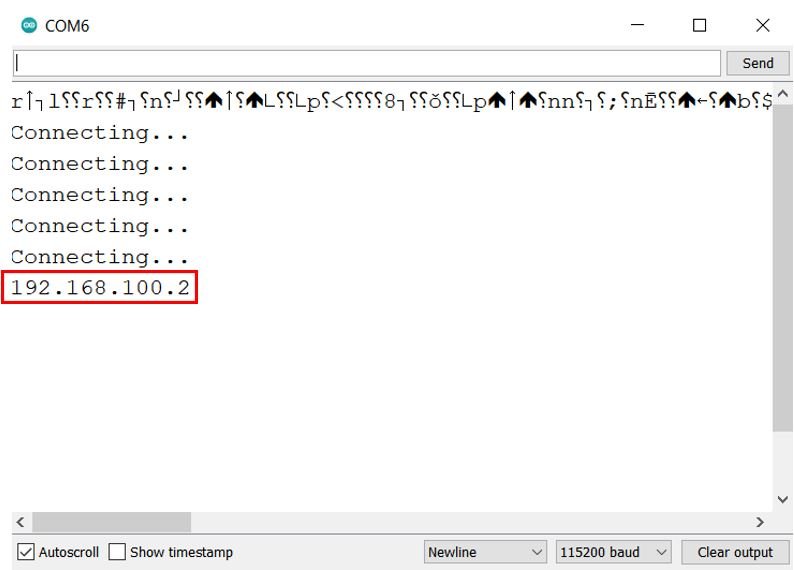
Type that IP address in a web browser and press enter. The web server will open up.
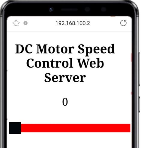
Now move the slider thumb to the right and the slider value will start increasing. This will generate a PWM signal with the corresponding value. Hence, the dc motor will start spinning at that particular speed. Once the value reaches 255, the speed will be maximum. Then start, moving the slider thumb to the left thereby decreasing the slider value. This will cause the DC motor to slow down and eventually stop when the value reaches 0 again.
Have a look at the demonstration video below:
You may also like to read:
- ESP-MESH Getting Started using painlessMesh Library and ESP32/ESP8266
- ESP8266 IoT Motion Detection Web Server with Email Alert
- HC-05 Bluetooth Interfacing with ESP8266 NodeMCU – Control GPIO Pins
- ESP8266 NodeMCU DS18B20 Web Server with Arduino IDE
- ESP32/ESP8266 Web Server with Input Data on HTML Form using Arduino IDE
- BME280 Web Server with ESP8266 NodeMCU (Arduino IDE)
Thank you very much for your project ” ESP8266 NodeMCU Web Server Control DC Motor Speed ” ESP8266 NodeMCU web server project. Iam using also ESP8266 you discuss brefily every point in this project. I try to add two buttons CW and CCW but did not succeed. It will be great if show me how to do this.
Thank you.