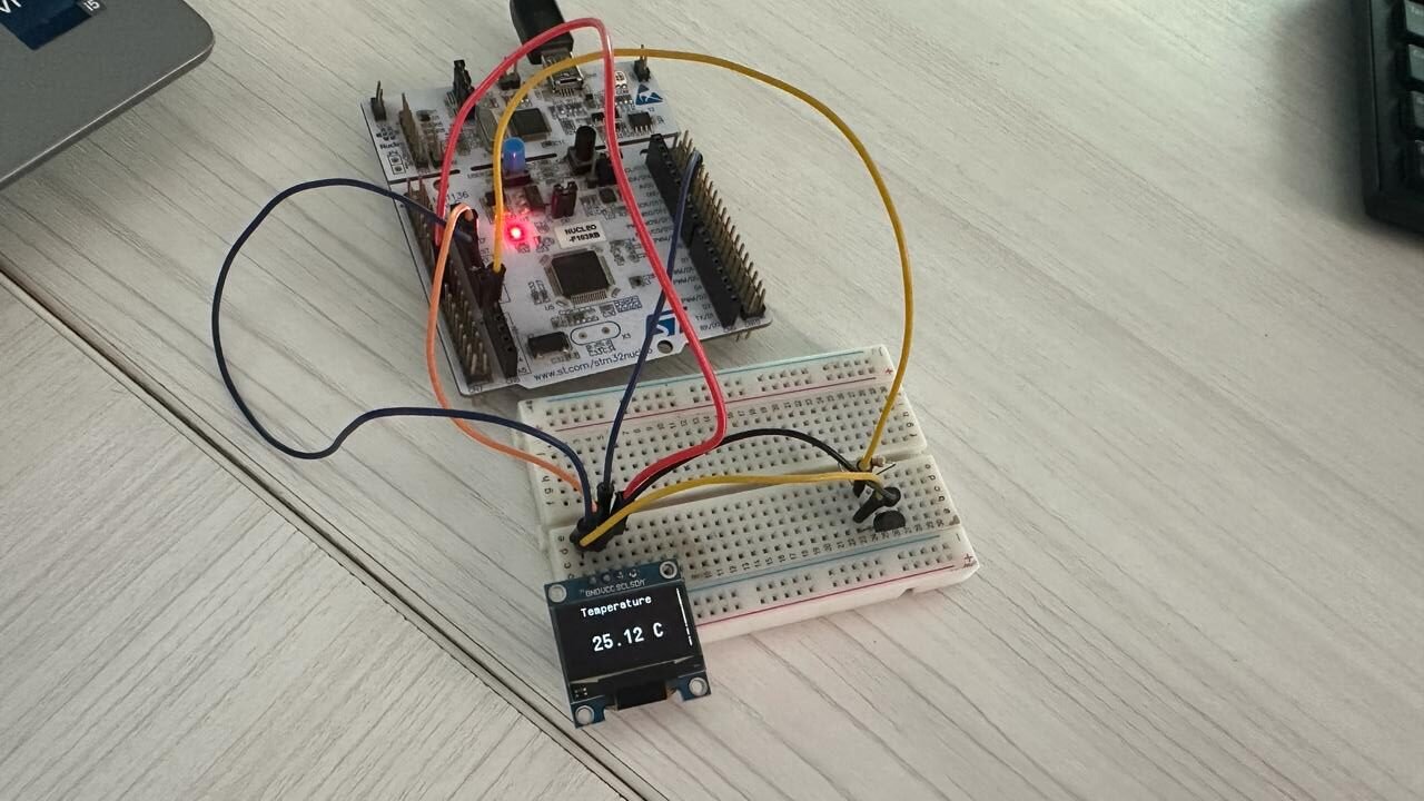
In this tutorial, we will learn how to interface DS18B20 temperature sensor with STM32 Nucleo and program it in STM32CubeIDE using HAL libraries. Firstly, we will briefly introduce you to DS18B20 sensor, then interface it with STM32 and program it for temperature measurement using STMCube IDE. For demonstration, we will connect an SSD1306 OLED with the STM32 Nucleo to display the sensor data on the OLED.
Recommended Components
The following components are used in this project or are helpful for getting started with STM32 Nucleo development.
| Component | How it’s used in this project | Buy on Amazon |
|---|---|---|
| STM32 Nucleo Board | The STM32 Nucleo-64 development board running this project. | Check Price |
| Micro USB / Mini-B USB Cable | Type-A to Mini-B cable to program and power the Nucleo over its onboard ST-Link. | Check Price |
| DS18B20 Temperature Sensor | Measures temperature and sends readings to the Nucleo over a single data wire. | Check Price |
| Resistor Kit (incl. 4.7kΩ) | Provides the 4.7kΩ pull-up resistor for the DS18B20 data line. | Check Price |
| 0.96″ SSD1306 OLED Display | Displays the measured temperature readings. | Check Price |
| Breadboard | Holds the sensor, OLED and resistor for the wiring. | Check Price |
| Jumper Wires | Connect the components to the Nucleo headers. | Check Price |
As an Amazon Associate we earn from qualifying purchases. Prices and availability are accurate as of the date/time indicated and are subject to change.
DS18B20 Introduction
DS18B20 is a temperature sensor that is single-wire programmable in nature. It is widely used to measure the temperature of chemical solutions and substances which are present in a hard environment. One of the advantages of using this sensor is that we only require a single pin of our microcontrollers to transfer data. Thus, it is extremely convenient to use this sensor with a microcontroller as we can measure multiple temperatures by using the least number of pins of our development board.
The table below shows some key characteristics of the ds18b120 sensor.
| Feature | Value |
|---|---|
| Operating Voltage | 3-5V |
| Temperature Range | -55°C to +125°C |
| Accuracy | ±0.5°C |
| Output Resolution | 9-12 bit |
Pinout Diagram
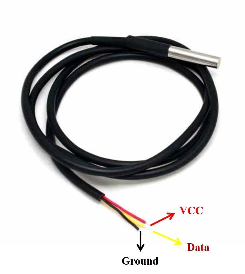
A waterproof version of this sensor is also available in the market. The following figures show the pinout of the DS18B20 sensors.
The following diagram shows the pinout of the normal DS18B20 temperature sensor.
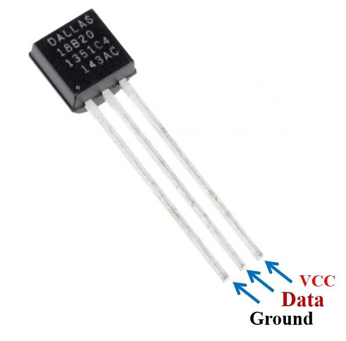
The table below lists the pin configurations:
| Pin | Description |
|---|---|
| VCC | This is the pin that powers up the sensor. It is 3.3V or 5V for STM32 Nucleo boards. |
| Data | This pin gives the temperature reading. |
| Ground | This pin is connected with the ground |
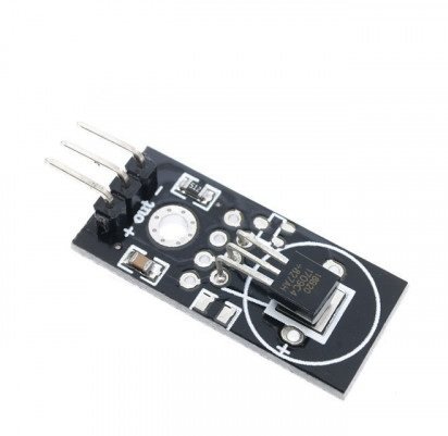
This temperature sensor also comes in a single package module which contains a sensor and a pull-up resistor. If you are using a module, you do not need to connect an external 4.7K ohm resistor. This is because the module already has an onboard pull-up resistor.
Interface DS18B20 sensor with STM32 Nucleo and OLED
We will need the following components for this project.
- STM32 Nucleo board
- DS18B20 Sensor
- 4.7k ohm resistor
- SSD1306 OLED
- Breadboard
- Connecting Wires
The connections between DS18B20 and Nucleo can be seen below.
| DS18B20 Sensor Pin | STM32 Nucleo Pin |
|---|---|
| GND | GND |
| Data | The data out pin will be connected with a GPIO output pin with a 4.7k ohm pull-up resistor. We will use PA1 to connect with the data pin. |
| VCC | 5V |
The connections between the OLED and Nucleo can be seen below.
| STM32 Nucleo | SSD1306 OLED Display |
|---|---|
| 3.3V | VCC |
| PB7 (I2C1_SDA) | SDA |
| PB6 (I2C1_SCL) | SCL |
| GND | GND |
Connect the DS18B20 sensor and OLED with STM32 Nucleo as shown in the schematic diagram below. We are using the same connections as specified in the tables above.

You can read this in-depth guide on OLED with STM32:
STM32 Nucleo DS18B20 with OLED using STMCube IDE
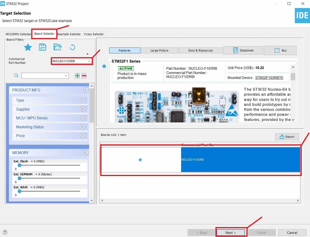
We will use STM32Cube IDE to program our STM32 board. Open the IDE and head over to a new project.
Then for the target selection, specify the STM32 Nucleo board number. After that click on any column as shown in the picture below. Then click the ‘Next’ button.
Specify the name of your project then click ‘Finish’ to complete the setup of your project.
Go to System Core > RCC then select ‘Crystal/Ceramic Resonator’ in from the High Speed Clock feature.
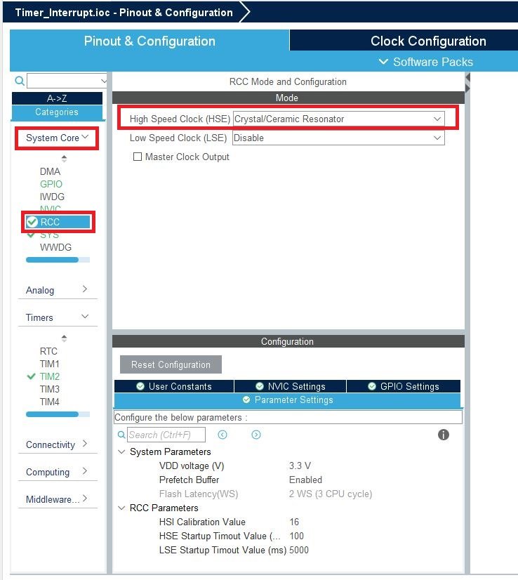
Now we have enabled the RCC external clock source.
Now head over to Timers > TIM1 and select the Clock Source as ‘Internal Clock.’ Then click the Parameter Settings and set the Prescaler as 63 and set the trigger event selection as Reset.

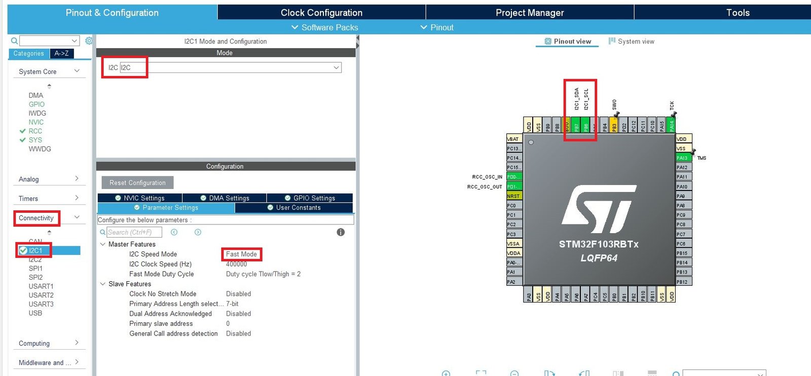
Head over to Connectivity > I2C1. Select the I2C mode as ‘I2C.’ Then go to ‘Parameter Settings’ and set the I2C speed mode as ‘Fast Mode.’ This is necessary for the SSD1306 OLED.
Setup PA1 as GPIO_Output pin and label it as DS18B20_Pin.

Clock Configuration
Next, go to the Clock Configuration found at the top. This will open the following window. Here we will select the clock frequency.
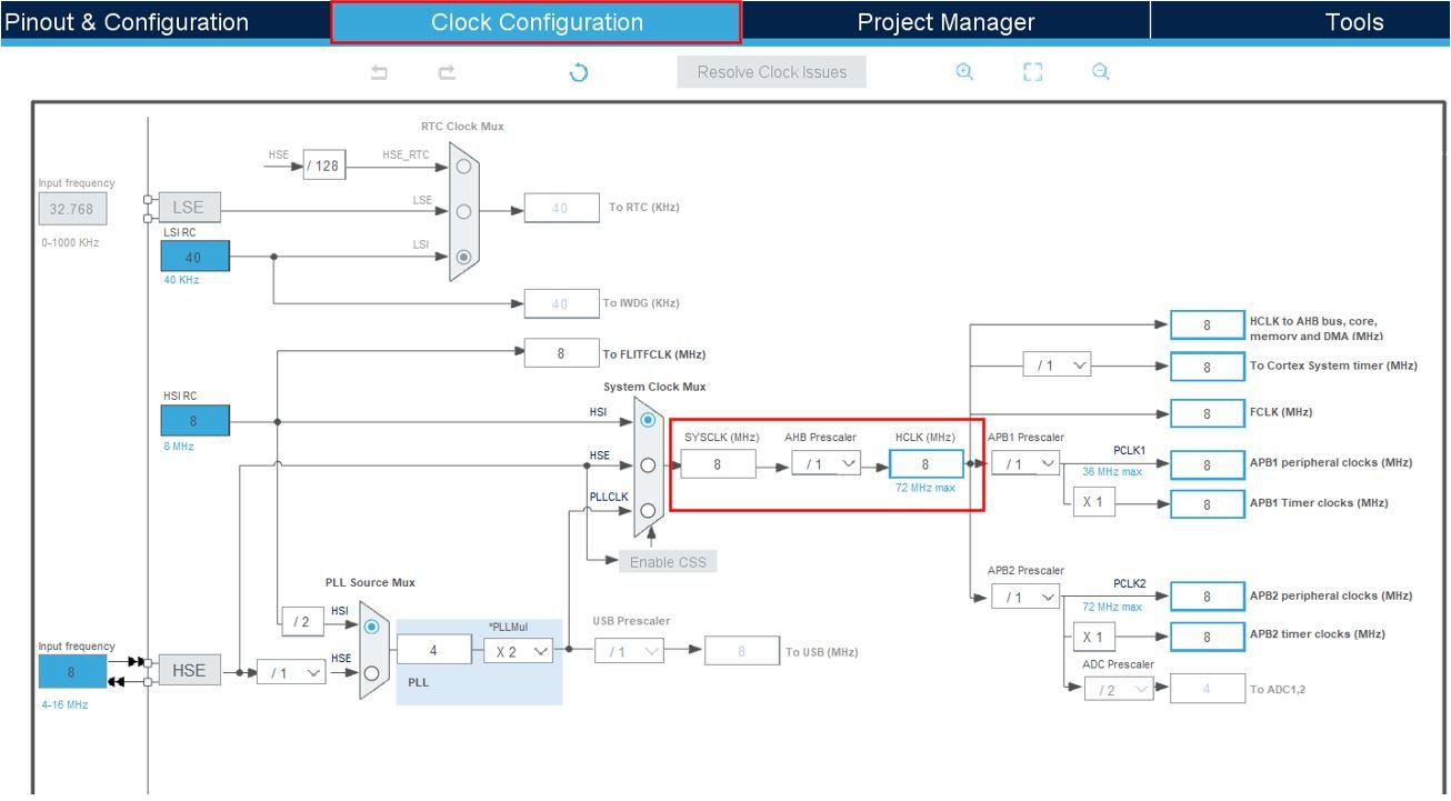
Set the system clock as 48 MHz. These are the configurations we have set:
Now we will save our file. Press Ctrl + S. The following window will appear. Click ‘Yes.’ This will generate a template code for you.

Another window will appear that will ask if you want to open the perspective. Click ‘Yes.’

STM32 DS18B20 Library
To acquire DS18B20 temperature readings with STM32 Nucleo using STMCube IDE, we will require ds18b20 and onewire libraries. Let us show you how to include them in your project in order to access the APIs provided by each of them.
ds18b20.h
Go to Core > Inc and create a new file called ‘ds18b20.h‘. Copy the following code and save it to this file.
/*
 * ds18b20.h
 *
 *	The MIT License.
 *  Created on: 20.09.2018
 *      Author: Mateusz Salamon
 *      www.msalamon.pl
 *      mateusz@msalamon.pl
 *
 */
#ifndef	_DS18B20_H
#define	_DS18B20_H

#include "onewire.h"
#include "main.h"
//
//	CONFIGURATION
//
extern TIM_HandleTypeDef htim1;
//	Remember to configure a timer on CubeMX 1us per tick
//	example 72 MHz cpu - Prescaler=(72-1), Counter period=65000
#define _DS18B20_MAX_SENSORS		    4
#define	_DS18B20_GPIO					DS18B20_Pin_GPIO_Port
#define	_DS18B20_PIN					DS18B20_Pin

#define	_DS18B20_TIMER					htim1

//#define _DS18B20_USE_CRC

//
//	Sensor structure
//
typedef struct
{
	uint8_t 	Address[8];
	float 		Temperature;
	uint8_t		ValidDataFlag;
} Ds18b20Sensor_t;

//
//	DEFINES
//
#define DS18B20_FAMILY_CODE				0x28

#define DS18B20_CMD_ALARMSEARCH			0xEC
#define DS18B20_CMD_CONVERTTEMP			0x44

#define DS18B20_STEP_12BIT		0.0625
#define DS18B20_STEP_11BIT		0.125
#define DS18B20_STEP_10BIT		0.25
#define DS18B20_STEP_9BIT		0.5

#define DS18B20_RESOLUTION_R1	6 // Resolution bit R1
#define DS18B20_RESOLUTION_R0	5 // Resolution bit R0

#ifdef _DS18B20_USE_CRC
#define DS18B20_DATA_LEN	9
#else
#define DS18B20_DATA_LEN	5
#endif

typedef enum {
	DS18B20_Resolution_9bits = 9,
	DS18B20_Resolution_10bits = 10,
	DS18B20_Resolution_11bits = 11,
	DS18B20_Resolution_12bits = 12
} DS18B20_Resolution_t;

//
//	FUNCTIONS
//

// 	Init
void		DS18B20_Init(DS18B20_Resolution_t resolution);
//	Settings
uint8_t 	DS18B20_GetResolution(uint8_t number); // Get the sensor resolution
uint8_t 	DS18B20_SetResolution(uint8_t number, DS18B20_Resolution_t resolution);	// Set the sensor resolution
// Control
uint8_t 	DS18B20_Start(uint8_t number); // Start conversion of one sensor
void 		DS18B20_StartAll(void);	// Start conversion for all sensors
uint8_t		DS18B20_Read(uint8_t number, float* destination); // Read one sensor
void 		DS18B20_ReadAll(void);	// Read all connected sensors
uint8_t 	DS18B20_Is(uint8_t* ROM); // Check if ROM address is DS18B20 family
uint8_t 	DS18B20_AllDone(void);	// Check if all sensor's conversion is done
//	ROMs
void		DS18B20_GetROM(uint8_t number, uint8_t* ROM); // Get sensor's ROM from 'number' position
void		DS18B20_WriteROM(uint8_t number, uint8_t* ROM); // Write a ROM to 'number' position in sensors table
// Return functions
uint8_t 	DS18B20_Quantity(void);	// Returns quantity of connected sensors
uint8_t		DS18B20_GetTemperature(uint8_t number, float* destination); // Returns 0 if read data is invalid
#endif
onewire.h
Go to Core > Inc and create a new file called ‘onewire.h‘. Copy the following code and save it to this file.
/*
 * onewire.h
 *
 *	The MIT License.
 *  Created on: 20.09.2018
 *      Author: Mateusz Salamon
 *      www.msalamon.pl
 *      mateusz@msalamon.pl
 *
 */
#ifndef ONEWIRE_H
#define ONEWIRE_H

#ifdef __cplusplus
extern C {
#endif
#include "stm32f1xx_hal.h"
//
//	1-Wire bus structure
//
typedef struct {
	GPIO_TypeDef* GPIOx;           // Bus GPIO Port
	uint16_t GPIO_Pin;             // Bus GPIO Pin
	uint8_t LastDiscrepancy;       // For searching purpose
	uint8_t LastFamilyDiscrepancy; // For searching purpose
	uint8_t LastDeviceFlag;        // For searching purpose
	uint8_t ROM_NO[8];             // 8-byte ROM addres last found device
} OneWire_t;

//
//	COMMANDS
//
#define ONEWIRE_CMD_RSCRATCHPAD			0xBE
#define ONEWIRE_CMD_WSCRATCHPAD			0x4E
#define ONEWIRE_CMD_CPYSCRATCHPAD		0x48
#define ONEWIRE_CMD_RECEEPROM			0xB8
#define ONEWIRE_CMD_RPWRSUPPLY			0xB4
#define ONEWIRE_CMD_SEARCHROM			0xF0
#define ONEWIRE_CMD_READROM				0x33
#define ONEWIRE_CMD_MATCHROM			0x55
#define ONEWIRE_CMD_SKIPROM				0xCC

//
//	FUNCTIONS
//

//
// Initialisation
//
void OneWire_Init(OneWire_t* OneWireStruct, GPIO_TypeDef* GPIOx, uint16_t GPIO_Pin);

//
// Reset bus
//
uint8_t OneWire_Reset(OneWire_t* OneWireStruct);

//
// Searching
//
void OneWire_ResetSearch(OneWire_t* OneWireStruct);
uint8_t OneWire_First(OneWire_t* OneWireStruct);
uint8_t OneWire_Next(OneWire_t* OneWireStruct);
uint8_t OneWire_Search(OneWire_t* OneWireStruct, uint8_t command);

//
// Writing/Reading
//
void OneWire_WriteBit(OneWire_t* OneWireStruct, uint8_t bit);
uint8_t OneWire_ReadBit(OneWire_t* OneWireStruct);
void OneWire_WriteByte(OneWire_t* OneWireStruct, uint8_t byte);
uint8_t OneWire_ReadByte(OneWire_t* OneWireStruct);

//
// ROM operations
//
void OneWire_GetFullROM(OneWire_t* OneWireStruct, uint8_t *firstIndex);
void OneWire_Select(OneWire_t* OneWireStruct, uint8_t* addr);
void OneWire_SelectWithPointer(OneWire_t* OneWireStruct, uint8_t* ROM);

//
//	CRC calculating
//
uint8_t OneWire_CRC8(uint8_t* addr, uint8_t len);
#ifdef __cplusplus
}
#endif
#endif
ds18b20.c
Go to Core > Inc and create a new file called ‘ds18b20.c‘. Copy the following code and save it to this file.
/*
 * ds18b20.c
 *
 *	The MIT License.
 *  Created on: 20.09.2018
 *      Author: Mateusz Salamon
 *      www.msalamon.pl
 *      mateusz@msalamon.pl
 *
 */
#include "ds18b20.h"

//
//	VARIABLES
//
Ds18b20Sensor_t	ds18b20[_DS18B20_MAX_SENSORS];

OneWire_t OneWire;
uint8_t	OneWireDevices;
uint8_t TempSensorCount=0;

//
//	FUNCTIONS
//

//
//	Start conversion of @number sensor
//
uint8_t DS18B20_Start(uint8_t number)
{
	if( number >= TempSensorCount) // If read sensor is not availible
		return 0;

	if (!DS18B20_Is((uint8_t*)&ds18b20[number].Address)) // Check if sensor is DS18B20 family
		return 0;

	OneWire_Reset(&OneWire); // Reset the bus
	OneWire_SelectWithPointer(&OneWire, (uint8_t*)ds18b20[number].Address); // Select the sensor by ROM
	OneWire_WriteByte(&OneWire, DS18B20_CMD_CONVERTTEMP); // Convert command

	return 1;
}

//
//	Start conversion on all sensors
//
void DS18B20_StartAll()
{
	OneWire_Reset(&OneWire); // Reset the bus
	OneWire_WriteByte(&OneWire, ONEWIRE_CMD_SKIPROM); // Skip ROM command
	OneWire_WriteByte(&OneWire, DS18B20_CMD_CONVERTTEMP); // Start conversion on all sensors
}

//
//	Read one sensor
//
uint8_t DS18B20_Read(uint8_t number, float *destination)
{
	if( number >= TempSensorCount) // If read sensor is not availible
		return 0;

	uint16_t temperature;
	uint8_t resolution;
	float result;
	uint8_t i = 0;
	uint8_t data[DS18B20_DATA_LEN];
#ifdef _DS18B20_USE_CRC
	uint8_t crc;

#endif


	if (!DS18B20_Is((uint8_t*)&ds18b20[number].Address)) // Check if sensor is DS18B20 family
		return 0;

	if (!OneWire_ReadBit(&OneWire)) // Check if the bus is released
		return 0; // Busy bus - conversion is not finished

	OneWire_Reset(&OneWire); // Reset the bus
	OneWire_SelectWithPointer(&OneWire, (uint8_t*)&ds18b20[number].Address); // Select the sensor by ROM
	OneWire_WriteByte(&OneWire, ONEWIRE_CMD_RSCRATCHPAD); // Read scratchpad command

	for (i = 0; i < DS18B20_DATA_LEN; i++) // Read scratchpad
		data[i] = OneWire_ReadByte(&OneWire);

#ifdef _DS18B20_USE_CRC
	crc = OneWire_CRC8(data, 8); // CRC calculation

	if (crc != data[8])
		return 0; // CRC invalid
#endif
	temperature = data[0] | (data[1] << 8); // Temperature is 16-bit length

	OneWire_Reset(&OneWire); // Reset the bus

	resolution = ((data[4] & 0x60) >> 5) + 9; // Sensor's resolution from scratchpad's byte 4

	switch (resolution) // Chceck the correct value dur to resolution
	{
		case DS18B20_Resolution_9bits:
			result = temperature*(float)DS18B20_STEP_9BIT;
		break;
		case DS18B20_Resolution_10bits:
			result = temperature*(float)DS18B20_STEP_10BIT;
		 break;
		case DS18B20_Resolution_11bits:
			result = temperature*(float)DS18B20_STEP_11BIT;
		break;
		case DS18B20_Resolution_12bits:
			result = temperature*(float)DS18B20_STEP_12BIT;
		 break;
		default:
			result = 0xFF;
	}

	*destination = result;

	return 1; //temperature valid
}

uint8_t DS18B20_GetResolution(uint8_t number)
{
	if( number >= TempSensorCount)
		return 0;

	uint8_t conf;

	if (!DS18B20_Is((uint8_t*)&ds18b20[number].Address))
		return 0;

	OneWire_Reset(&OneWire); // Reset the bus
	OneWire_SelectWithPointer(&OneWire, (uint8_t*)&ds18b20[number].Address); // Select the sensor by ROM
	OneWire_WriteByte(&OneWire, ONEWIRE_CMD_RSCRATCHPAD); // Read scratchpad command

	OneWire_ReadByte(&OneWire);
	OneWire_ReadByte(&OneWire);
	OneWire_ReadByte(&OneWire);
	OneWire_ReadByte(&OneWire);

	conf = OneWire_ReadByte(&OneWire); // Register 5 is the configuration register with resolution
	conf &= 0x60; // Mask two resolution bits
	conf >>= 5; // Shift to left
	conf += 9; // Get the result in number of resolution bits

	return conf;
}

uint8_t DS18B20_SetResolution(uint8_t number, DS18B20_Resolution_t resolution)
{
	if( number >= TempSensorCount)
		return 0;

	uint8_t th, tl, conf;
	if (!DS18B20_Is((uint8_t*)&ds18b20[number].Address))
		return 0;

	OneWire_Reset(&OneWire); // Reset the bus
	OneWire_SelectWithPointer(&OneWire, (uint8_t*)&ds18b20[number].Address); // Select the sensor by ROM
	OneWire_WriteByte(&OneWire, ONEWIRE_CMD_RSCRATCHPAD); // Read scratchpad command

	OneWire_ReadByte(&OneWire);
	OneWire_ReadByte(&OneWire);

	th = OneWire_ReadByte(&OneWire); 	// Writing to scratchpad begins from the temperature alarms bytes
	tl = OneWire_ReadByte(&OneWire); 	// 	so i have to store them.
	conf = OneWire_ReadByte(&OneWire);	// Config byte

	if (resolution == DS18B20_Resolution_9bits) // Bits setting
	{
		conf &= ~(1 << DS18B20_RESOLUTION_R1);
		conf &= ~(1 << DS18B20_RESOLUTION_R0);
	}
	else if (resolution == DS18B20_Resolution_10bits)
	{
		conf &= ~(1 << DS18B20_RESOLUTION_R1);
		conf |= 1 << DS18B20_RESOLUTION_R0;
	}
	else if (resolution == DS18B20_Resolution_11bits)
	{
		conf |= 1 << DS18B20_RESOLUTION_R1;
		conf &= ~(1 << DS18B20_RESOLUTION_R0);
	}
	else if (resolution == DS18B20_Resolution_12bits)
	{
		conf |= 1 << DS18B20_RESOLUTION_R1;
		conf |= 1 << DS18B20_RESOLUTION_R0;
	}

	OneWire_Reset(&OneWire); // Reset the bus
	OneWire_SelectWithPointer(&OneWire, (uint8_t*)&ds18b20[number].Address); // Select the sensor by ROM
	OneWire_WriteByte(&OneWire, ONEWIRE_CMD_WSCRATCHPAD); // Write scratchpad command

	OneWire_WriteByte(&OneWire, th); // Write 3 bytes to scratchpad
	OneWire_WriteByte(&OneWire, tl);
	OneWire_WriteByte(&OneWire, conf);

	OneWire_Reset(&OneWire); // Reset the bus
	OneWire_SelectWithPointer(&OneWire, (uint8_t*)&ds18b20[number].Address); // Select the sensor by ROM
	OneWire_WriteByte(&OneWire, ONEWIRE_CMD_CPYSCRATCHPAD); // Copy scratchpad to EEPROM

	return 1;
}

uint8_t DS18B20_Is(uint8_t* ROM)
{
	if (*ROM == DS18B20_FAMILY_CODE) // Check family code
		return 1;
	return 0;
}

uint8_t DS18B20_AllDone(void)
{
	return OneWire_ReadBit(&OneWire); // Bus is down - busy
}

void DS18B20_ReadAll(void)
{
	uint8_t i;

	if (DS18B20_AllDone())
	{
		for(i = 0; i < TempSensorCount; i++) // All detected sensors loop
		{
			ds18b20[i].ValidDataFlag = 0;

			if (DS18B20_Is((uint8_t*)&ds18b20[i].Address))
			{
				ds18b20[i].ValidDataFlag = DS18B20_Read(i, &ds18b20[i].Temperature); // Read single sensor
			}
		}
	}
}

void DS18B20_GetROM(uint8_t number, uint8_t* ROM)
{
	if( number >= TempSensorCount)
		number = TempSensorCount;

	uint8_t i;

	for(i = 0; i < 8; i++)
		ROM[i] = ds18b20[number].Address[i];
}

void DS18B20_WriteROM(uint8_t number, uint8_t* ROM)
{
	if( number >= TempSensorCount)
		return;

	uint8_t i;

	for(i = 0; i < 8; i++)
		ds18b20[number].Address[i] = ROM[i]; // Write ROM into sensor's structure
}

uint8_t DS18B20_Quantity(void)
{
	return TempSensorCount;
}

uint8_t DS18B20_GetTemperature(uint8_t number, float* destination)
{
	if(!ds18b20[number].ValidDataFlag)
		return 0;

	*destination = ds18b20[number].Temperature;
	return 1;

}

void DS18B20_Init(DS18B20_Resolution_t resolution)
{
	uint8_t next = 0, i = 0, j;
	OneWire_Init(&OneWire, DS18B20_Pin_GPIO_Port, DS18B20_Pin_Pin); // Init OneWire bus

	next = OneWire_First(&OneWire); // Search first OneWire device
	while(next)
	{
		TempSensorCount++;
		OneWire_GetFullROM(&OneWire, (uint8_t*)&ds18b20[i++].Address); // Get the ROM of next sensor
		next = OneWire_Next(&OneWire);
		if(TempSensorCount >= _DS18B20_MAX_SENSORS) // More sensors than set maximum is not allowed
			break;
	}

	for(j = 0; j < i; j++)
	{
		DS18B20_SetResolution(j, resolution); // Set the initial resolution to sensor

		DS18B20_StartAll(); // Start conversion on all sensors
	}
}
onewire.c
Go to Core > Inc and create a new file called ‘onewire.c‘ Copy the following code and save it to this file.
/*
 * onewire.c
 *
 *	The MIT License.
 *  Created on: 20.09.2018
 *      Author: Mateusz Salamon
 *      www.msalamon.pl
 *      mateusz@msalamon.pl
 *
 */
#include "onewire.h"
#include "ds18b20.h"

//
//	Delay function for constant 1-Wire timings
//
void OneWire_Delay(uint16_t us)
{
	_DS18B20_TIMER.Instance->CNT = 0;
	while(_DS18B20_TIMER.Instance->CNT <= us);
}

//
//	Bus direction control
//
void OneWire_BusInputDirection(OneWire_t *onewire)
{
	GPIO_InitTypeDef	GPIO_InitStruct;
	GPIO_InitStruct.Mode = GPIO_MODE_INPUT; // Set as input
	GPIO_InitStruct.Pull = GPIO_NOPULL; // No pullup - the pullup resistor is external
	GPIO_InitStruct.Speed = GPIO_SPEED_FREQ_MEDIUM; // Medium GPIO frequency
	GPIO_InitStruct.Pin = onewire->GPIO_Pin; // Pin for 1-Wire bus
	HAL_GPIO_Init(onewire->GPIOx, &GPIO_InitStruct); // Reinitialize
}

void OneWire_BusOutputDirection(OneWire_t *onewire)
{
	GPIO_InitTypeDef	GPIO_InitStruct;
	GPIO_InitStruct.Mode = GPIO_MODE_OUTPUT_OD; // Set as open-drain output
	GPIO_InitStruct.Pull = GPIO_NOPULL; // No pullup - the pullup resistor is external
	GPIO_InitStruct.Speed = GPIO_SPEED_FREQ_MEDIUM; // Medium GPIO frequency
	GPIO_InitStruct.Pin = onewire->GPIO_Pin; // Pin for 1-Wire bus
	HAL_GPIO_Init(onewire->GPIOx, &GPIO_InitStruct); // Reinitialize
}

//
//	Bus pin output state control
//
void OneWire_OutputLow(OneWire_t *onewire)
{
	onewire->GPIOx->BSRR = onewire->GPIO_Pin<<16; // Reset the 1-Wire pin
}

void OneWire_OutputHigh(OneWire_t *onewire)
{
	onewire->GPIOx->BSRR = onewire->GPIO_Pin; // Set the 1-Wire pin
}

//
//	1-Wire bus reset signal
//
//	Returns:
//	0 - Reset ok
//	1 - Error
//
uint8_t OneWire_Reset(OneWire_t* onewire)
{
	uint8_t i;

	OneWire_OutputLow(onewire);  // Write bus output low
	OneWire_BusOutputDirection(onewire);
	OneWire_Delay(480); // Wait 480 us for reset

	OneWire_BusInputDirection(onewire); // Release the bus by switching to input
	OneWire_Delay(70);

	i = HAL_GPIO_ReadPin(onewire->GPIOx, onewire->GPIO_Pin); // Check if bus is low
															 // if it's high - no device is presence on the bus
	OneWire_Delay(410);

	return i;
}

//
//	Writing/Reading operations
//
void OneWire_WriteBit(OneWire_t* onewire, uint8_t bit)
{
	if (bit) // Send '1',
	{
		OneWire_OutputLow(onewire);	// Set the bus low
		OneWire_BusOutputDirection(onewire);
		OneWire_Delay(6);

		OneWire_BusInputDirection(onewire); // Release bus - bit high by pullup
		OneWire_Delay(64);
	}
	else // Send '0'
	{
		OneWire_OutputLow(onewire); // Set the bus low
		OneWire_BusOutputDirection(onewire);
		OneWire_Delay(60);

		OneWire_BusInputDirection(onewire); // Release bus - bit high by pullup
		OneWire_Delay(10);
	}
}

uint8_t OneWire_ReadBit(OneWire_t* onewire)
{
	uint8_t bit = 0; // Default read bit state is low

	OneWire_OutputLow(onewire); // Set low to initiate reading
	OneWire_BusOutputDirection(onewire);
	OneWire_Delay(2);

	OneWire_BusInputDirection(onewire); // Release bus for Slave response
	OneWire_Delay(10);

	if (HAL_GPIO_ReadPin(onewire->GPIOx, onewire->GPIO_Pin)) // Read the bus state
		bit = 1;

	OneWire_Delay(50); // Wait for end of read cycle

	return bit;
}

void OneWire_WriteByte(OneWire_t* onewire, uint8_t byte)
{
	uint8_t i = 8;

	do
	{
		OneWire_WriteBit(onewire, byte & 1); // LSB first
		byte >>= 1;
	} while(--i);
}

uint8_t OneWire_ReadByte(OneWire_t* onewire)
{
	uint8_t i = 8, byte = 0;

	do{
		byte >>= 1;
		byte |= (OneWire_ReadBit(onewire) << 7); // LSB first
	} while(--i);

	return byte;
}

//
// 1-Wire search operations
//
void OneWire_ResetSearch(OneWire_t* onewire)
{
	// Clear the search results
	onewire->LastDiscrepancy = 0;
	onewire->LastDeviceFlag = 0;
	onewire->LastFamilyDiscrepancy = 0;
}

uint8_t OneWire_Search(OneWire_t* onewire, uint8_t command)
{
	uint8_t id_bit_number;
	uint8_t last_zero, rom_byte_number, search_result;
	uint8_t id_bit, cmp_id_bit;
	uint8_t rom_byte_mask, search_direction;

	id_bit_number = 1;
	last_zero = 0;
	rom_byte_number = 0;
	rom_byte_mask = 1;
	search_result = 0;

	if (!onewire->LastDeviceFlag) // If last device flag is not set
	{
		if (OneWire_Reset(onewire)) // Reset bus
		{
			// If error while reset - reset search results
			onewire->LastDiscrepancy = 0;
			onewire->LastDeviceFlag = 0;
			onewire->LastFamilyDiscrepancy = 0;
			return 0;
		}

		OneWire_WriteByte(onewire, command); // Send searching command

		// Searching loop, Maxim APPLICATION NOTE 187
		do
		{
			id_bit = OneWire_ReadBit(onewire); // Read a bit 1
			cmp_id_bit = OneWire_ReadBit(onewire); // Read the complement of bit 1

			if ((id_bit == 1) && (cmp_id_bit == 1)) // 11 - data error
			{
				break;
			}
			else
			{
				if (id_bit != cmp_id_bit)
				{
					search_direction = id_bit;  // Bit write value for search
				}
				else // 00 - 2 devices
				{
					// Table 3. Search Path Direction
					if (id_bit_number < onewire->LastDiscrepancy)
					{
						search_direction = ((onewire->ROM_NO[rom_byte_number] & rom_byte_mask) > 0);
					}
					else
					{
						// If bit is equal to last - pick 1
						// If not - then pick 0
						search_direction = (id_bit_number == onewire->LastDiscrepancy);
					}

					if (search_direction == 0) // If 0 was picked, write it to LastZero
					{
						last_zero = id_bit_number;

						if (last_zero < 9) // Check for last discrepancy in family
						{
							onewire->LastFamilyDiscrepancy = last_zero;
						}
					}
				}

				if (search_direction == 1)
				{
					onewire->ROM_NO[rom_byte_number] |= rom_byte_mask; // Set the bit in the ROM byte rom_byte_number
				}
				else
				{
					onewire->ROM_NO[rom_byte_number] &= ~rom_byte_mask; // Clear the bit in the ROM byte rom_byte_number
				}

				OneWire_WriteBit(onewire, search_direction); // Search direction write bit

				id_bit_number++; // Next bit search - increase the id
				rom_byte_mask <<= 1; // Shoft the mask for next bit

				if (rom_byte_mask == 0) // If the mask is 0, it says the whole byte is read
				{
					rom_byte_number++; // Next byte number
					rom_byte_mask = 1; // Reset the mask - first bit
				}
			}
		} while(rom_byte_number < 8);  // Read 8 bytes

		if (!(id_bit_number < 65)) // If all read bits number is below 65 (8 bytes)
		{
			onewire->LastDiscrepancy = last_zero;

			if (onewire->LastDiscrepancy == 0) // If last discrepancy is 0 - last device found
			{
				onewire->LastDeviceFlag = 1; // Set the flag
			}

			search_result = 1; // Searching successful
		}
	}

	// If no device is found - reset search data and return 0
	if (!search_result || !onewire->ROM_NO[0])
	{
		onewire->LastDiscrepancy = 0;
		onewire->LastDeviceFlag = 0;
		onewire->LastFamilyDiscrepancy = 0;
		search_result = 0;
	}

	return search_result;
}

//
//	Return first device on 1-Wire bus
//
uint8_t OneWire_First(OneWire_t* onewire)
{
	OneWire_ResetSearch(onewire);

	return OneWire_Search(onewire, ONEWIRE_CMD_SEARCHROM);
}

//
//	Return next device on 1-Wire bus
//
uint8_t OneWire_Next(OneWire_t* onewire)
{
   /* Leave the search state alone */
   return OneWire_Search(onewire, ONEWIRE_CMD_SEARCHROM);
}

//
//	Select a device on bus by address
//
void OneWire_Select(OneWire_t* onewire, uint8_t* addr)
{
	uint8_t i;
	OneWire_WriteByte(onewire, ONEWIRE_CMD_MATCHROM); // Match ROM command

	for (i = 0; i < 8; i++)
	{
		OneWire_WriteByte(onewire, *(addr + i));
	}
}

//
//	Select a device on bus by pointer to ROM address
//
void OneWire_SelectWithPointer(OneWire_t* onewire, uint8_t *ROM)
{
	uint8_t i;
	OneWire_WriteByte(onewire, ONEWIRE_CMD_MATCHROM); // Match ROM command

	for (i = 0; i < 8; i++)
	{
		OneWire_WriteByte(onewire, *(ROM + i));
	}
}

//
//	Get the ROM of found device
//
void OneWire_GetFullROM(OneWire_t* onewire, uint8_t *firstIndex)
{
	uint8_t i;
	for (i = 0; i < 8; i++) {
		*(firstIndex + i) = onewire->ROM_NO[i];
	}
}

//
//	Calculate CRC
//
uint8_t OneWire_CRC8(uint8_t *addr, uint8_t len) {
	uint8_t crc = 0, inbyte, i, mix;

	while (len--)
	{
		inbyte = *addr++;
		for (i = 8; i; i--)
		{
			mix = (crc ^ inbyte) & 0x01;
			crc >>= 1;
			if (mix)
			{
				crc ^= 0x8C;
			}
			inbyte >>= 1;
		}
	}

	return crc;
}

//
//	1-Wire initialization
//
void OneWire_Init(OneWire_t* onewire, GPIO_TypeDef* GPIOx, uint16_t GPIO_Pin)
{
	HAL_TIM_Base_Start(&_DS18B20_TIMER); // Start the delay timer

	onewire->GPIOx = GPIOx; // Save 1-wire bus pin
	onewire->GPIO_Pin = GPIO_Pin;

	// 1-Wire bit bang initialization
	OneWire_BusOutputDirection(onewire);
	OneWire_OutputHigh(onewire);
	HAL_Delay(100);
	OneWire_OutputLow(onewire);
	HAL_Delay(100);
	OneWire_OutputHigh(onewire);
	HAL_Delay(200);
}
STM32 OLED Library
As we are working with an SSD1306 OLED with our STM32 Nucleo, we will require the ssd1306.h and fonts.h libraries. These libraries will be used to access different functions that will enable us to display texts and numbers on the OLED in various ways.
ssd1306.h
Go to Core > Inc and create a new file called ‘ssd1306.h‘ Copy the following code from this link and save it to this file.
In ssd1306.h file, remove #include “i2c.h” (line 49) and add extern I2C_HandleTypeDef hi2c1;
fonts.h
Go to Core > Inc and create a new file called ‘fonts.h‘ Copy the following code from this link and save it to this file.
ssd1306.c
Similarly, head over to Core > Src and create a new file called ‘ssd1306.c‘ Copy the following code from this link and save it to this file.
fonts.c
Head over to Core > Src and create a new file called ‘fonts.c‘ Copy the following code from this link and save it to this file.
STM32 Nucleo DS18B20 Sensor with OLED Code
Now let us look at our main.c file that was generated. Inside the main.c file, make sure the following code is part of your script by including the lines of code given below. We will use HAL library functions and DS18B20 libraries to access the sensor data and display them on the OLED using the fonts.h and ssd1306.h APIs.
#include "main.h"
#include "onewire.h"
#include "ds18b20.h"
#include "string.h"
#include <stdio.h>
#include "fonts.h"
#include "ssd1306.h"

I2C_HandleTypeDef hi2c1;

TIM_HandleTypeDef htim1;

void SystemClock_Config(void);
static void MX_I2C1_Init(void);

float temperature;
char string[64];

int main(void)
{
  HAL_Init();
  SystemClock_Config();
  MX_GPIO_Init();
  MX_TIM1_Init();
  MX_I2C1_Init();

  SSD1306_Init();

  DS18B20_Init(DS18B20_Resolution_12bits);

  while (1)
  {
	  DS18B20_ReadAll();
          DS18B20_StartAll();
		uint8_t ROM_tmp[8];
		uint8_t i;

	for(i = 0; i < DS18B20_Quantity(); i++)
		{
			if(DS18B20_GetTemperature(i, &temperature))
			{
				DS18B20_GetROM(i, ROM_tmp);
				memset(string, 0, sizeof(string));
				sprintf(string, "%.2f C", temperature);
				SSD1306_GotoXY (20, 0);
				SSD1306_Puts ("Temperature", &Font_7x10, 1);
				SSD1306_GotoXY (25, 30);
				SSD1306_Puts (string, &Font_11x18, 1);
				SSD1306_UpdateScreen();
			}
		}
		HAL_Delay(1000);
  }
}
How does the Code Works?
We start off by including the necessary libraries for this project which include the DS18B20 libraries for the sensor functionality and fonts.h and ssd1306.h libraries for the OLED functionality.
#include "main.h"
#include "onewire.h"
#include "ds18b20.h"
#include "string.h"
#include <stdio.h>
#include "fonts.h"
#include "ssd1306.h"
main()
Inside the main function, first all the peripherals are initialized, system clock is configured and all the configured peripherals are initialized.
  HAL_Init();
  SystemClock_Config();
  MX_GPIO_Init();
  MX_TIM1_Init();
  MX_I2C1_Init();
Next, we initialize the OLED. We use the SSD1306_Init() function for initialization.
SSD1306_Init();Initialize the DS18B20 sensor with 12 bits resolution by calling DS18B20_Init() and specifiying the sensor resolution as a parameter inside this function.
DS18B20_Init(DS18B20_Resolution_12bits);
Read and Display Sensor Data
Inside the infinite while loop, we start accessing the temperature readings from the DS18B20 sensor and display them on the OLED screen.
  while (1)
  {
	  DS18B20_ReadAll();
      DS18B20_StartAll();
		uint8_t ROM_tmp[8];
		uint8_t i;

	for(i = 0; i < DS18B20_Quantity(); i++)
		{
			if(DS18B20_GetTemperature(i, &temperature))
			{
				DS18B20_GetROM(i, ROM_tmp);
				memset(string, 0, sizeof(string));
				sprintf(string, "%.2f C", temperature);
				SSD1306_GotoXY (20, 0);
				SSD1306_Puts ("Temperature", &Font_7x10, 1);
				SSD1306_GotoXY (25, 30);
				SSD1306_Puts (string, &Font_11x18, 1);
				SSD1306_UpdateScreen();
			}
		}
		HAL_Delay(1000);
  }
To start reading the DS18B20 sensor, we first call the function DS18B20_ReadAll(). This reads the temperatures of all the connected sensors in a loop. Then we call DS18B20_Start(). The DS18B20_Start() function resets the onewire bus, skips the ROM command and starts the conversion on all the sensors.
DS18B20_ReadAll();
DS18B20_StartAll();
After that we run a for loop to obtain the temperature readings using DS18B20_GetTemperature() and display them on the OLED. In our case, the loop runs once as we are using a single DS18B20 sensor.
If the DS18B20_GetTemperature() Then we convert the float temperature variable to string consisting of reading and its unit and display them on the OLED.
To display the sensor data on the OLED, first, we will set the x and the y axis position from where the text should start. SSD1306_gotoXY() function is used to set the write pointers. We have passed (20,0) as the parameter to display the text ‘Temperature’. We use SSD1306_Puts() function to display the temperature readings along with its unit on the screen at starting x-axis and y-axis at (25,30). This function takes in three parameters which is the string to be displayed, the font name and the color of the text. Additionally, call SSD1306_UpdateScreen() to display the text on the screen. The readings will update on the screen after every second.
	for(i = 0; i < DS18B20_Quantity(); i++)
		{
			if(DS18B20_GetTemperature(i, &temperature))
			{
				DS18B20_GetROM(i, ROM_tmp);
				memset(string, 0, sizeof(string));
				sprintf(string, "%.2f C", temperature);
				SSD1306_GotoXY (20, 0);
				SSD1306_Puts ("Temperature", &Font_7x10, 1);
				SSD1306_GotoXY (25, 30);
				SSD1306_Puts (string, &Font_11x18, 1);
				SSD1306_UpdateScreen();
			}
		}
		HAL_Delay(1000);
  }
main.c file
This is how a complete main.c file will be after modification.
/* USER CODE BEGIN Header */
/**
  ******************************************************************************
  * @file           : main.c
  * @brief          : Main program body
  ******************************************************************************
  * @attention
  *
  * Copyright (c) 2024 STMicroelectronics.
  * All rights reserved.
  *
  * This software is licensed under terms that can be found in the LICENSE file
  * in the root directory of this software component.
  * If no LICENSE file comes with this software, it is provided AS-IS.
  *
  ******************************************************************************
  */
/* USER CODE END Header */
/* Includes ------------------------------------------------------------------*/
#include "main.h"

/* Private includes ----------------------------------------------------------*/
/* USER CODE BEGIN Includes */
extern I2C_HandleTypeDef hi2c1;
TIM_HandleTypeDef htim1;
#include "fonts.h"
#include "ssd1306.h"
#include <stdio.h>
#include "onewire.h"
#include "ds18b20.h"
/* USER CODE END Includes */

/* Private typedef -----------------------------------------------------------*/
/* USER CODE BEGIN PTD */


/* USER CODE END PTD */

/* Private define ------------------------------------------------------------*/
/* USER CODE BEGIN PD */

/* USER CODE END PD */

/* Private macro -------------------------------------------------------------*/
/* USER CODE BEGIN PM */

/* USER CODE END PM */

/* Private variables ---------------------------------------------------------*/
I2C_HandleTypeDef hi2c1;

TIM_HandleTypeDef htim1;

/* USER CODE BEGIN PV */
float temperature;
char string[64];

/* USER CODE END PV */

/* Private function prototypes -----------------------------------------------*/
void SystemClock_Config(void);
static void MX_GPIO_Init(void);
static void MX_I2C1_Init(void);
static void MX_TIM1_Init(void);
/* USER CODE BEGIN PFP */

/* USER CODE END PFP */

/* Private user code ---------------------------------------------------------*/
/* USER CODE BEGIN 0 */

/* USER CODE END 0 */

/**
  * @brief  The application entry point.
  * @retval int
  */
int main(void)
{
  /* USER CODE BEGIN 1 */

  /* USER CODE END 1 */

  /* MCU Configuration--------------------------------------------------------*/

  /* Reset of all peripherals, Initializes the Flash interface and the Systick. */
  HAL_Init();

  /* USER CODE BEGIN Init */

  /* USER CODE END Init */

  /* Configure the system clock */
  SystemClock_Config();

  /* USER CODE BEGIN SysInit */

  /* USER CODE END SysInit */

  /* Initialize all configured peripherals */
  MX_GPIO_Init();
  MX_I2C1_Init();
  MX_TIM1_Init();
  /* USER CODE BEGIN 2 */
  HAL_TIM_Base_Start(&htim1);
  DS18B20_Init(DS18B20_Resolution_12bits);
  uint8_t res = SSD1306_Init();

  /* USER CODE END 2 */

  /* Infinite loop */
  /* USER CODE BEGIN WHILE */
  while (1)
  {
	  DS18B20_ReadAll();

	        DS18B20_StartAll();

	  		uint8_t ROM_tmp[8];
	  		uint8_t i;

	  	for(i = 0; i < DS18B20_Quantity(); i++)
	  		{
	  			if(DS18B20_GetTemperature(i, &temperature))
	  			{
	  				DS18B20_GetROM(i, ROM_tmp);
	  				memset(string, 0, sizeof(string));
	  				sprintf(string, "%.2f C", temperature);
	  				SSD1306_GotoXY (20, 0);
	  				SSD1306_Puts ("Temperature", &Font_7x10, 1);
	  				SSD1306_GotoXY (25, 30);
	  				SSD1306_Puts (string, &Font_11x18, 1);
	  				SSD1306_UpdateScreen();
	  			}
	  		}
	  		HAL_Delay(1000);


    /* USER CODE END WHILE */

    /* USER CODE BEGIN 3 */
  }
  /* USER CODE END 3 */
}

/**
  * @brief System Clock Configuration
  * @retval None
  */
void SystemClock_Config(void)
{
  RCC_OscInitTypeDef RCC_OscInitStruct = {0};
  RCC_ClkInitTypeDef RCC_ClkInitStruct = {0};

  /** Initializes the RCC Oscillators according to the specified parameters
  * in the RCC_OscInitTypeDef structure.
  */
  RCC_OscInitStruct.OscillatorType = RCC_OSCILLATORTYPE_HSE;
  RCC_OscInitStruct.HSEState = RCC_HSE_ON;
  RCC_OscInitStruct.HSEPredivValue = RCC_HSE_PREDIV_DIV1;
  RCC_OscInitStruct.HSIState = RCC_HSI_ON;
  RCC_OscInitStruct.PLL.PLLState = RCC_PLL_ON;
  RCC_OscInitStruct.PLL.PLLSource = RCC_PLLSOURCE_HSE;
  RCC_OscInitStruct.PLL.PLLMUL = RCC_PLL_MUL9;
  if (HAL_RCC_OscConfig(&RCC_OscInitStruct) != HAL_OK)
  {
    Error_Handler();
  }

  /** Initializes the CPU, AHB and APB buses clocks
  */
  RCC_ClkInitStruct.ClockType = RCC_CLOCKTYPE_HCLK|RCC_CLOCKTYPE_SYSCLK
                              |RCC_CLOCKTYPE_PCLK1|RCC_CLOCKTYPE_PCLK2;
  RCC_ClkInitStruct.SYSCLKSource = RCC_SYSCLKSOURCE_PLLCLK;
  RCC_ClkInitStruct.AHBCLKDivider = RCC_SYSCLK_DIV1;
  RCC_ClkInitStruct.APB1CLKDivider = RCC_HCLK_DIV2;
  RCC_ClkInitStruct.APB2CLKDivider = RCC_HCLK_DIV1;

  if (HAL_RCC_ClockConfig(&RCC_ClkInitStruct, FLASH_LATENCY_2) != HAL_OK)
  {
    Error_Handler();
  }
}

/**
  * @brief I2C1 Initialization Function
  * @param None
  * @retval None
  */
static void MX_I2C1_Init(void)
{

  /* USER CODE BEGIN I2C1_Init 0 */

  /* USER CODE END I2C1_Init 0 */

  /* USER CODE BEGIN I2C1_Init 1 */

  /* USER CODE END I2C1_Init 1 */
  hi2c1.Instance = I2C1;
  hi2c1.Init.ClockSpeed = 400000;
  hi2c1.Init.DutyCycle = I2C_DUTYCYCLE_2;
  hi2c1.Init.OwnAddress1 = 0;
  hi2c1.Init.AddressingMode = I2C_ADDRESSINGMODE_7BIT;
  hi2c1.Init.DualAddressMode = I2C_DUALADDRESS_DISABLE;
  hi2c1.Init.OwnAddress2 = 0;
  hi2c1.Init.GeneralCallMode = I2C_GENERALCALL_DISABLE;
  hi2c1.Init.NoStretchMode = I2C_NOSTRETCH_DISABLE;
  if (HAL_I2C_Init(&hi2c1) != HAL_OK)
  {
    Error_Handler();
  }
  /* USER CODE BEGIN I2C1_Init 2 */

  /* USER CODE END I2C1_Init 2 */

}

/**
  * @brief TIM1 Initialization Function
  * @param None
  * @retval None
  */
static void MX_TIM1_Init(void)
{

  /* USER CODE BEGIN TIM1_Init 0 */

  /* USER CODE END TIM1_Init 0 */

  TIM_ClockConfigTypeDef sClockSourceConfig = {0};
  TIM_MasterConfigTypeDef sMasterConfig = {0};

  /* USER CODE BEGIN TIM1_Init 1 */

  /* USER CODE END TIM1_Init 1 */
  htim1.Instance = TIM1;
  htim1.Init.Prescaler = 63;
  htim1.Init.CounterMode = TIM_COUNTERMODE_UP;
  htim1.Init.Period = 65535;
  htim1.Init.ClockDivision = TIM_CLOCKDIVISION_DIV1;
  htim1.Init.RepetitionCounter = 0;
  htim1.Init.AutoReloadPreload = TIM_AUTORELOAD_PRELOAD_DISABLE;
  if (HAL_TIM_Base_Init(&htim1) != HAL_OK)
  {
    Error_Handler();
  }
  sClockSourceConfig.ClockSource = TIM_CLOCKSOURCE_INTERNAL;
  if (HAL_TIM_ConfigClockSource(&htim1, &sClockSourceConfig) != HAL_OK)
  {
    Error_Handler();
  }
  sMasterConfig.MasterOutputTrigger = TIM_TRGO_RESET;
  sMasterConfig.MasterSlaveMode = TIM_MASTERSLAVEMODE_DISABLE;
  if (HAL_TIMEx_MasterConfigSynchronization(&htim1, &sMasterConfig) != HAL_OK)
  {
    Error_Handler();
  }
  /* USER CODE BEGIN TIM1_Init 2 */

  /* USER CODE END TIM1_Init 2 */

}

/**
  * @brief GPIO Initialization Function
  * @param None
  * @retval None
  */
static void MX_GPIO_Init(void)
{
  GPIO_InitTypeDef GPIO_InitStruct = {0};
/* USER CODE BEGIN MX_GPIO_Init_1 */
/* USER CODE END MX_GPIO_Init_1 */

  /* GPIO Ports Clock Enable */
  __HAL_RCC_GPIOD_CLK_ENABLE();
  __HAL_RCC_GPIOA_CLK_ENABLE();
  __HAL_RCC_GPIOB_CLK_ENABLE();

  /*Configure GPIO pin Output Level */
  HAL_GPIO_WritePin(DS18B20_Pin_GPIO_Port, DS18B20_Pin_Pin, GPIO_PIN_RESET);

  /*Configure GPIO pin : DS18B20_Pin_Pin */
  GPIO_InitStruct.Pin = DS18B20_Pin_Pin;
  GPIO_InitStruct.Mode = GPIO_MODE_OUTPUT_PP;
  GPIO_InitStruct.Pull = GPIO_NOPULL;
  GPIO_InitStruct.Speed = GPIO_SPEED_FREQ_LOW;
  HAL_GPIO_Init(DS18B20_Pin_GPIO_Port, &GPIO_InitStruct);

/* USER CODE BEGIN MX_GPIO_Init_2 */
/* USER CODE END MX_GPIO_Init_2 */
}

/* USER CODE BEGIN 4 */

/* USER CODE END 4 */

/**
  * @brief  This function is executed in case of error occurrence.
  * @retval None
  */
void Error_Handler(void)
{
  /* USER CODE BEGIN Error_Handler_Debug */
  /* User can add his own implementation to report the HAL error return state */
  __disable_irq();
  while (1)
  {
  }
  /* USER CODE END Error_Handler_Debug */
}

#ifdef  USE_FULL_ASSERT
/**
  * @brief  Reports the name of the source file and the source line number
  *         where the assert_param error has occurred.
  * @param  file: pointer to the source file name
  * @param  line: assert_param error line source number
  * @retval None
  */
void assert_failed(uint8_t *file, uint32_t line)
{
  /* USER CODE BEGIN 6 */
  /* User can add his own implementation to report the file name and line number,
     ex: printf("Wrong parameters value: file %s on line %d\r\n", file, line) */
  /* USER CODE END 6 */
}
#endif /* USE_FULL_ASSERT */
Save the main.c file after modifying it. Now we are ready to build our project.
Building the Project
To build our project press Ctrl + B or go to Project > Build All.
Your project will start building. After a few moments, your project will be successfully built if there are no errors.
Demonstration
Next press the RUN button in the IDE. The ‘Edit configuration’ window will open up. Click ‘OK’.
After a few moments, the code will be successfully sent to the STM32 board.
Otherwise, press the RESET button on your STM32
Once the code is uploaded to the board, the OLED will start displaying the temperature readings on the screen, which will update to new values after every second.

Watch the video below:
Conclusion
In conclusion, this tutorial offers a practical approach to interfacing the DS18B20 temperature sensor with an STM32 Nucleo board using STM32CubeIDE and HAL libraries. By following the outlined steps, users can successfully measure temperature and display the readings on an SSD1306 OLED. This project serves as a solid foundation for developing more advanced temperature monitoring applications and integrating additional sensors or communication protocols for expanded functionality.
You may also like to read: