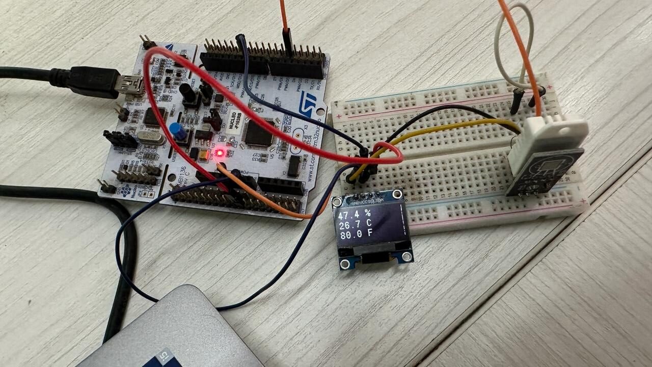
In this tutorial, we will learn how to interface DHT22 temperature and humidity sensor with STM32 Nucleo and program it in STM32CubeIDE using HAL libraries. At first, we will briefly introduce you to DHT22 sensor, then interface it with our STM32 and program it for temperature and humidity measurement using STMCube IDE. For demonstration, we will connect an SSD1306 OLED with the STM32 Nucleo to view the sensor data on the OLED.
Recommended Components
The following components are used in this project or are helpful for getting started with STM32 Nucleo development.
| Component | How it’s used in this project | Buy on Amazon |
|---|---|---|
| STM32 Nucleo Board | The STM32 Nucleo-64 development board running this project. | Check Price |
| Micro USB / Mini-B USB Cable | Type-A to Mini-B cable to program and power the Nucleo over its onboard ST-Link. | Check Price |
| DHT22 Sensor | Measures temperature and humidity and sends readings to the Nucleo. | Check Price |
| 0.96″ SSD1306 OLED Display | Displays the temperature and humidity readings. | Check Price |
| Breadboard | Holds the sensor and OLED for the wiring. | Check Price |
| Jumper Wires | Connect the components to the Nucleo headers. | Check Price |
As an Amazon Associate we earn from qualifying purchases. Prices and availability are accurate as of the date/time indicated and are subject to change.
DHT22 Introduction
The DHT22 is an inexpensive sensor which measures relative humidity and temperature. It provides a calibrated digital output with a 1-wire protocol. It measures temperature and humidity with higher accuracy and supports a wider range as compared to DHT11.
DHT sensors are pre-calibrated. We can directly connect them with our STM32 board to obtain sensor output readings. They are internally composed of a humidity sensing sensor and a thermistor. These two components measure humidity and temperature respectively.
DHT22 Pinout
The following figure shows the pinout diagram of DHT sensors. DHT sensor consists of four pins. But on DHT modules only three pins are exposed to the pinout of the module and the 10k ohm pull-up resistor is internally connected to pin 2.
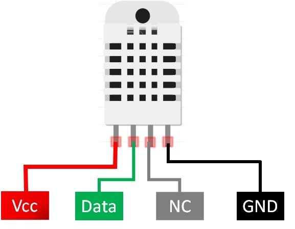
The following lists the pinout of the DHT sensor and their brief description. Pin number starts from left to right when you hold the sensor from the front end. It also shows how these pins will be connected with the STM32 Nucleo board.
| DHT22 Pins | STM32 Nucleo |
|---|---|
| 1 (VCC) | This is the power supply pin (3.3V-5V). Connect it with 3.3V or 5V pin. |
| 2 (Data) | Connect it with any digital output pin. |
| 3 (NC) | Not used |
| 4 (GND) | Connect it with GND pin |
- VCC is the power supply pin. Apply voltage in a range of 3.3 V to 5.0 V to this pin.
- Data Out is the digital output pin. It sends out the value of measured temperature and humidity in the form of serial data
- N/C is not connected
- GND: Connect the GND pin
Interface DHT22 sensor with STM32 Nucleo and OLED
We will need the following components for this project.
- STM32 Nucleo board
- DHT22 sensor
- 10k ohm resistor (not required if using the DHT22 sensor module)
- SSD1306 OLED
- Breadboard
- Connecting Wires
The connections between the DHT22 and Nucleo can be seen below.
| DHT22 Sensor Pin | STM32 Nucleo Pin |
|---|---|
| 1 (VCC) | 5V |
| 2 (Data) | The data out pin will be connected with any GPIO output pin with a 10k ohm pull-up resistor. We will use PB14 to connect with the data pin. |
| 3 (NC) | This pin is not used |
| 4 (GND) | GND |
The connections between the OLED and Nucleo can be seen below.
| STM32 Nucleo | SSD1306 OLED Display |
|---|---|
| 5V | VCC |
| PB7 | SDA |
| PB6 | SCL |
| GND | GND |
Connect the DHT22 sensor and OLED with STM32 Nucleo as shown in the schematic diagram below. We are using the same connections as specified in the tables above.

STM32 Nucleo DHT22 with STMCube IDE
We will use STM32Cube IDE to program our STM32 board. Open the IDE and head over to a new project.
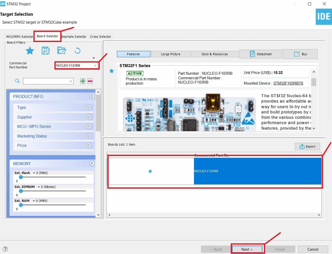
Then for the target selection, specify the STM32 Nucleo board number. After that click on any column as shown in the picture below. Then click the ‘Next’ button.
Specify the name of your project then click ‘Finish’ to complete the setup of your project.
First of all go to System Core > RCC then select ‘Crystal/Ceramic Resonator’ in from the High Speed Clock feature.

Now we have enabled the RCC external clock source.
Now head over to Timers > TIM1 and select the Clock Source as ‘Internal Clock.’ Then click the Parameter Settings and set the Prescaler as 71.

Setup PB14 as GPIO_Output. This pin will be connected with the Pin2 data pin of the DHT22 sensor.

Now head over to Connectivity > I2C1. Select the I2C mode as ‘I2C.’ Then go to ‘Parameter Settings’ and set the I2C speed mode as ‘Fast Mode.’ This is necessary for the SSD1306 OLED.

Clock Configuration
Next, go to the Clock Configuration found at the top. This will open the following window. Here we will select the clock frequency.
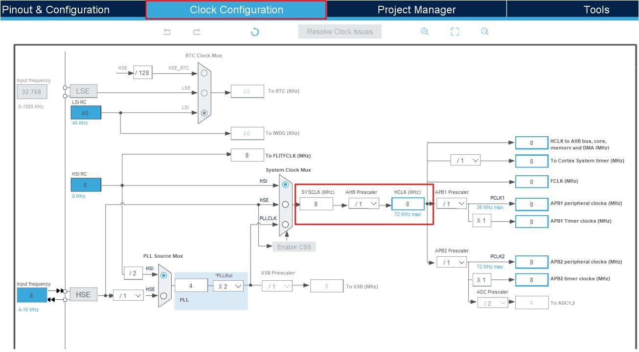
You can specify your system clock. We will set it as 72 MHz. These are the configurations we have set:

Now we will save our file. Press Ctrl + S. The following window will appear. Click ‘Yes.’ This will generate a template code for you.

Another window will appear that will ask if you want to open the perspective. Click ‘Yes.’

STM32 OLED Library
As we are working with an SSD1306 OLED with our STM32 Nucleo, we will require the ssd1306.h and fonts.h libraries. These libraries will be used to access different functions that will enable us to display texts and numbers on the OLED in various ways.
ssd1306.h
Go to Core > Inc and create a new file called ‘ssd1306.h‘ Copy the following code from this link and save it to this file.
In ssd1306.h file, remove #include “i2c.h” (line 49) and add extern I2C_HandleTypeDef hi2c1;
fonts.h
Go to Core > Inc and create a new file called ‘fonts.h‘ Copy the following code from this link and save it to this file.
ssd1306.c
Similarly, head over to Core > Src and create a new file called ‘ssd1306.c‘ Copy the following code from this link and save it to this file.
fonts.c
Head over to Core > Src and
STM32 Nucleo DHT22 Sensor with OLED Code
Now let us look at our main.c file that was generated. Inside the main.c file, make sure the following code is part of your script by including the lines of code given below. We will use HAL library functions to access the DHT22 sensor data and display them on the OLED using the fonts.h and ssd1306.h APIs.
#include "main.h"

#include "fonts.h"
#include "ssd1306.h"
#include "stdio.h"

I2C_HandleTypeDef hi2c1;

TIM_HandleTypeDef htim1;

void SystemClock_Config(void);
static void MX_GPIO_Init(void);
static void MX_I2C1_Init(void);
static void MX_TIM1_Init(void);

#define DHT22_PORT GPIOB
#define DHT22_PIN GPIO_PIN_14

uint8_t hum1, hum2, tempC1, tempC2, SUM, CHECK;
uint32_t pMillis, cMillis;
float temp_Celsius = 0;
float temp_Fahrenheit = 0;
float Humidity = 0;
uint8_t hum_integral, hum_decimal, tempC_integral, tempC_decimal, tempF_integral, tempF_decimal;
char string[15];

void microDelay (uint16_t delay)
{
  __HAL_TIM_SET_COUNTER(&htim1, 0);
  while (__HAL_TIM_GET_COUNTER(&htim1) < delay);
}

uint8_t DHT22_Start (void)
{
  uint8_t Response = 0;
  GPIO_InitTypeDef GPIO_InitStructPrivate = {0};
  GPIO_InitStructPrivate.Pin = DHT22_PIN;
  GPIO_InitStructPrivate.Mode = GPIO_MODE_OUTPUT_PP;
  GPIO_InitStructPrivate.Speed = GPIO_SPEED_FREQ_LOW;
  GPIO_InitStructPrivate.Pull = GPIO_NOPULL;
  HAL_GPIO_Init(DHT22_PORT, &GPIO_InitStructPrivate);
  HAL_GPIO_WritePin (DHT22_PORT, DHT22_PIN, 0);
  microDelay (1300);
  HAL_GPIO_WritePin (DHT22_PORT, DHT22_PIN, 1);
  microDelay (30);
  GPIO_InitStructPrivate.Mode = GPIO_MODE_INPUT;
  GPIO_InitStructPrivate.Pull = GPIO_PULLUP;
  HAL_GPIO_Init(DHT22_PORT, &GPIO_InitStructPrivate);
  microDelay (40);
  if (!(HAL_GPIO_ReadPin (DHT22_PORT, DHT22_PIN)))
  {
    microDelay (80);
    if ((HAL_GPIO_ReadPin (DHT22_PORT, DHT22_PIN))) Response = 1;
  }
  pMillis = HAL_GetTick();
  cMillis = HAL_GetTick();
  while ((HAL_GPIO_ReadPin (DHT22_PORT, DHT22_PIN)) && pMillis + 2 > cMillis)
  {
    cMillis = HAL_GetTick();
  }
  return Response;
}

uint8_t DHT22_Read (void)
{
  uint8_t x,y;
  for (x=0;x<8;x++)
  {
    pMillis = HAL_GetTick();
    cMillis = HAL_GetTick();
    while (!(HAL_GPIO_ReadPin (DHT22_PORT, DHT22_PIN)) && pMillis + 2 > cMillis)
    {
      cMillis = HAL_GetTick();
    }
    microDelay (40);
    if (!(HAL_GPIO_ReadPin (DHT22_PORT, DHT22_PIN)))   // if the pin is low
      y&= ~(1<<(7-x));
    else
      y|= (1<<(7-x));
    pMillis = HAL_GetTick();
    cMillis = HAL_GetTick();
    while ((HAL_GPIO_ReadPin (DHT22_PORT, DHT22_PIN)) && pMillis + 2 > cMillis)
    {  // wait for the pin to go low
      cMillis = HAL_GetTick();
    }
  }
  return y;
}

int main(void)
{
  HAL_Init();
  SystemClock_Config();

  MX_GPIO_Init();
  MX_I2C1_Init();
  MX_TIM1_Init();

  HAL_TIM_Base_Start(&htim1);
  SSD1306_Init();

  while (1)
  {
	  if(DHT22_Start())
	     {
	       hum1 = DHT22_Read();
	       hum2 = DHT22_Read();
	       tempC1 = DHT22_Read();
	       tempC2 = DHT22_Read();
	       SUM = DHT22_Read();
	       CHECK = hum1 + hum2 + tempC1 + tempC2;
	       if (CHECK == SUM)
	       {
	         if (tempC1>127)
	         {
	           temp_Celsius = (float)tempC2/10*(-1);
	         }
	         else
	         {
	           temp_Celsius = (float)((tempC1<<8)|tempC2)/10;
	         }

	         temp_Fahrenheit = temp_Celsius * 9/5 + 32;

	         Humidity = (float) ((hum1<<8)|hum2)/10;

	         SSD1306_GotoXY (0, 0);
	         hum_integral = Humidity;
	         hum_decimal = Humidity*10-hum_integral*10;
	         sprintf(string,"%d.%d %%  ", hum_integral, hum_decimal);
	         SSD1306_Puts (string, &Font_11x18, 1);

	         SSD1306_GotoXY (0, 20);
	         if (temp_Celsius < 0)
	         {
	           tempC_integral = temp_Celsius *(-1);
	           tempC_decimal = temp_Celsius*(-10)-tempC_integral*10;
	           sprintf(string,"-%d.%d C   ", tempC_integral, tempC_decimal);
	         }
	         else
	         {
	           tempC_integral = temp_Celsius;
	           tempC_decimal = temp_Celsius*10-tempC_integral*10;
	           sprintf(string,"%d.%d C   ", tempC_integral, tempC_decimal);
	         }
	         SSD1306_Puts (string, &Font_11x18, 1);

	         SSD1306_GotoXY (0, 40);
	         if(temp_Fahrenheit < 0)
	         {
	           tempF_integral = temp_Fahrenheit*(-1);
	           tempF_decimal = temp_Fahrenheit*(-10)-tempF_integral*10;
	           sprintf(string,"-%d.%d F   ", tempF_integral, tempF_decimal);
	         }
	         else
	         {
	           tempF_integral = temp_Fahrenheit;
	           tempF_decimal = temp_Fahrenheit*10-tempF_integral*10;
	           sprintf(string,"%d.%d F   ", tempF_integral, tempF_decimal);
	         }
	         SSD1306_Puts (string, &Font_11x18, 1);
	         SSD1306_UpdateScreen();
	       }
	     }
	     HAL_Delay(1000);
  }
}
How Code Works?
We start off by including fonts.h and ssd1306.h libraries for the OLED functionality.
#include "fonts.h"
#include "ssd1306.h"
#include "stdio.h"
Next, we define the GPIO pin that will be used to connect with the data pin of the DHT22 sensor. We have configured GPIO pin 14. Moreover, the selected port is GPIOB. We setup PB14 as GPIO_Output in the configuration.
#define DHT22_PORT GPIOB
#define DHT22_PIN GPIO_PIN_14
Next, we have the microDelay() function, where we set the timer counter register value on runtime as ‘0.’ It continues to run while the timer counter register value which is the single parameter of this function, remains less than the ‘delay’.
void microDelay (uint16_t delay)
{
  __HAL_TIM_SET_COUNTER(&htim1, 0);
  while (__HAL_TIM_GET_COUNTER(&htim1) < delay);
}
DHT22_Start()
Then we have the DHT22_Start() function that initializes the GPIO connected with the data pin for DHT22 data measurements and returns the ‘Response.’
uint8_t DHT22_Start (void)
{
  uint8_t Response = 0;
  GPIO_InitTypeDef GPIO_InitStructPrivate = {0};
  GPIO_InitStructPrivate.Pin = DHT22_PIN;
  GPIO_InitStructPrivate.Mode = GPIO_MODE_OUTPUT_PP;
  GPIO_InitStructPrivate.Speed = GPIO_SPEED_FREQ_LOW;
  GPIO_InitStructPrivate.Pull = GPIO_NOPULL;

  HAL_GPIO_Init(DHT22_PORT, &GPIO_InitStructPrivate); // set the pin as output

  HAL_GPIO_WritePin (DHT22_PORT, DHT22_PIN, 0);   // pull the pin low
  microDelay (1300);   // wait for 1300us
  HAL_GPIO_WritePin (DHT22_PORT, DHT22_PIN, 1);   // pull the pin high
  microDelay (30);   // wait for 30us
  GPIO_InitStructPrivate.Mode = GPIO_MODE_INPUT;
  GPIO_InitStructPrivate.Pull = GPIO_PULLUP;
  HAL_GPIO_Init(DHT22_PORT, &GPIO_InitStructPrivate); // set the pin as input
  microDelay (40);
  if (!(HAL_GPIO_ReadPin (DHT22_PORT, DHT22_PIN)))
  {
    microDelay (80);
    if ((HAL_GPIO_ReadPin (DHT22_PORT, DHT22_PIN))) Response = 1;
  }
  pMillis = HAL_GetTick();
  cMillis = HAL_GetTick();
  while ((HAL_GPIO_ReadPin (DHT22_PORT, DHT22_PIN)) && pMillis + 2 > cMillis)
  {
    cMillis = HAL_GetTick();
  }
  return Response;
}
Inside this function, we will first define the GPIO initialization structure. This includes the pin, mode, speed and enabling pull-up resistors. We are configuring ‘DHT22_PIN’ GPIO pin in GPIO_MODE_OUTPUT_PP operating mode. The speed of the selected pin is set as GPIO_SPEED_FREQ_LOW and no pull-up activation is specified on the selected pin.
GPIO_InitTypeDef GPIO_InitStructPrivate = {0};
  GPIO_InitStructPrivate.Pin = DHT22_PIN;
  GPIO_InitStructPrivate.Mode = GPIO_MODE_OUTPUT_PP;
  GPIO_InitStructPrivate.Speed = GPIO_SPEED_FREQ_LOW;
  GPIO_InitStructPrivate.Pull = GPIO_NOPULL;
Using HAL_GPIO_Init() function, the GPIO peripheral is initialized according to the specified parameters in the GPIO_Init. This function takes in two parameters: the GPIO port and the pointer to the GPIO_InitTypeDef structure that holds the configuration parameters for the specified GPIO peripheral.
HAL_GPIO_Init(DHT22_PORT, &GPIO_InitStructPrivate);After setting the DHT22_PIN as an output, we will set the state of the pin as LOW using HAL_GPIO_WritePin() function. This function takes in three parameters which include the selected GPIO peripheral, GPIO port bit and the pin state respectively. We first pull the pin to a low state, then wait for 1300us using the microDelay() function and then pull the pin to a high state and wait for 30us.
HAL_GPIO_WritePin (DHT22_PORT, DHT22_PIN, 0);
  microDelay (1300);
  HAL_GPIO_WritePin (DHT22_PORT, DHT22_PIN, 1);
  microDelay (30);
Next, we configure the DHT22_PIN as an input and wait for 40us.
GPIO_InitStructPrivate.Mode = GPIO_MODE_INPUT;
  GPIO_InitStructPrivate.Pull = GPIO_PULLUP;
  HAL_GPIO_Init(DHT22_PORT, &GPIO_InitStructPrivate);
  microDelay (40);
Then we will use an if statement to check if the state of the pin is low. If the state is low, then we wait for another 80 us and if the state of the pin is now high then set the value of the ‘Response’ variable as 1. Next, we obtain the a tick value in milliseconds and save it in the ‘pMillis’ and ‘cMillis’ variables to monitor the previous and current tick value.
  if (!(HAL_GPIO_ReadPin (DHT22_PORT, DHT22_PIN)))
  {
    microDelay (80);
    if ((HAL_GPIO_ReadPin (DHT22_PORT, DHT22_PIN))) Response = 1;
  }
  pMillis = HAL_GetTick();
  cMillis = HAL_GetTick();
  while ((HAL_GPIO_ReadPin (DHT22_PORT, DHT22_PIN)) && pMillis + 2 > cMillis)
  {
    cMillis = HAL_GetTick();
  }
  return Response;
DHT_Read()
Inside the DHT_Read() function, we read from the DHT22 sensor. Inside this function, we run a for loop for 8 iterations and obtain the previous and current tick value in milliseconds. We then wait for the DHT22_PIN to go to a high state and keep on accessing the current tick value. Then we shift the bits according to the pin state and then wait for the pin to go to a low state meanwhile obtaining the current tick value in milliseconds.
uint8_t DHT22_Read (void)
{
  uint8_t x,y;
  for (x=0;x<8;x++)
  {
    pMillis = HAL_GetTick();
    cMillis = HAL_GetTick();
    while (!(HAL_GPIO_ReadPin (DHT22_PORT, DHT22_PIN)) && pMillis + 2 > cMillis)
    {
      cMillis = HAL_GetTick();
    }
    microDelay (40);
    if (!(HAL_GPIO_ReadPin (DHT22_PORT, DHT22_PIN)))   //pin is low
      y&= ~(1<<(7-x));
    else
      y|= (1<<(7-x));
    pMillis = HAL_GetTick();
    cMillis = HAL_GetTick();
    while ((HAL_GPIO_ReadPin (DHT22_PORT, DHT22_PIN)) && pMillis + 2 > cMillis)
    {
      cMillis = HAL_GetTick();
    }
  }
  return y;
}
main()
Inside the main function, first all the peripherals are initialized, system clock is configured and all the configured peripherals are initialized.
  HAL_Init();
  SystemClock_Config();

  MX_GPIO_Init();
  MX_I2C1_Init();
  MX_TIM1_Init();
After that we call HAL_TIM_Base_Start() to start the TIM base generation. This function takes in a single parameter which is the TIM_HandleTypeDef structure that holds the configuration parameters for TIM module.
HAL_TIM_Base_Start(&htim1);Next, we initialize the OLED. We use the SSD1306_Init() function for initialization.
SSD1306_Init();Read from Sensor
Inside the infinite while loop, if the DHT22_Start() function returns 1, then we first call the DHT22_Read function five times. The first time the DHT22 sensor is read, it acquires the first 8 bits of humidity and saves it in the variable ‘hum1.’ The second time the DHT22 sensor is read, it acquires the second 8 bits of humidity and saves it in the variable ‘hum2.’ Similarly, the third time the DHT22 sensor is read, it acquires the first 8 bits of temperature in Celsius and saves it in the variable ‘tempC1.’ The fourth time the DHT22 sensor is read, it acquires the second 8 bits of temperature in Celsius and saves it in the variable ‘tempC2.’ The fifth time the DHT22 sensor is read, it acquires all the combined readings as a sum and saves it in the variable ‘SUM.’
 hum1 = DHT22_Read();
 hum2 = DHT22_Read();
 tempC1 = DHT22_Read();
 tempC2 = DHT22_Read();
 SUM = DHT22_Read();
The ‘CHECK’ variable adds all the humidity and temperature in Celsius readings.
CHECK = hum1 + hum2 + tempC1 + tempC2;Obtain DHT22 Sensor Data
Next, we check if we are getting accurate readings which happens when the value held in the variable ‘SUM’ is equal to ‘CHECK’ then we move ahead and obtain the temperature reading in Celsius and save it in the variable ‘temp_Celsius.’ Both positive and negative temperature readings are catered through an if-else condition.
if (CHECK == SUM)
	       {
	         if (tempC1>127) // If TC1=10000000, negative temperature
	         {
	           temp_Celsius = (float)tempC2/10*(-1);
	         }
	         else
	         {
	           temp_Celsius = (float)((tempC1<<8)|tempC2)/10;
	         }
The temperature reading in Fahrenheit is calculated by multiplying the temperature reading in Celsius by 9/5 and adding 32 to it.
temp_Fahrenheit = temp_Celsius * 9/5 + 32;Similarly, the humidity reading is obtained in the following line of code and saved in the variable ‘Humidity.’
Humidity = (float) ((hum1<<8)|hum2)/10;Display on OLED
Next we will display the sensor data on the OLED after every second. First, we will set the x and the y axis position from where the text should start. SSD1306_gotoXY() function is used to set the write pointers. We have passed (0,0) as the parameter hence the text starts from the upper left corner. We find the relative humidity integral and decimal readings and use SSD1306_Puts() function to display it on the screen. This function takes in three parameters which is the string to be displayed, the font name and the color of the text.
   SSD1306_GotoXY (0, 0);
   hum_integral = Humidity;
   hum_decimal = Humidity*10-hum_integral*10;
  sprintf(string,"%d.%d %%  ", hum_integral, hum_decimal);
  SSD1306_Puts (string, &Font_11x18, 1);
Next, to display the temperature reading in Celsius, we set the starting x-axis and y-axis at (0,20). Then we find the temperature Celsius integral and decimal values and save them in their respective variables ‘tempC_integral’ and ‘tempC_decimal’. Both negative and positive temperature readings are taken into account through an if-else statement. Then using the function, SSD1306_Puts() we will display the temperature reading in Celsius on the screen.
	         SSD1306_GotoXY (0, 20);
	         if (temp_Celsius < 0)
	         {
	           tempC_integral = temp_Celsius *(-1);
	           tempC_decimal = temp_Celsius*(-10)-tempC_integral*10;
	           sprintf(string,"-%d.%d C   ", tempC_integral, tempC_decimal);
	         }
	         else
	         {
	           tempC_integral = temp_Celsius;  // Celsius integral
	           tempC_decimal = temp_Celsius*10-tempC_integral*10;
	           sprintf(string,"%d.%d C   ", tempC_integral, tempC_decimal);
	         }
	         SSD1306_Puts (string, &Font_11x18, 1);
Similarly, to display the temperature reading in Fahrenheit, we set the starting x-axis and y-axis at (0,40). Then we find the temperature Fahrenheit integral and decimal values and save them in their respective variables ‘tempF_integral’ and ‘tempF_decimal’. Both negative and positive temperature readings are taken into account through an if-else statement. Then using the function, SSD1306_Puts() we will display the temperature reading in Fahrenheit on the screen. Additionally, call SSD1306_UpdateScreen() to display the readings on the screen.
SSD1306_GotoXY (0, 40);
	         if(temp_Fahrenheit < 0)
	         {
	           tempF_integral = temp_Fahrenheit*(-1);
	           tempF_decimal = temp_Fahrenheit*(-10)-tempF_integral*10;
	           sprintf(string,"-%d.%d F   ", tempF_integral, tempF_decimal);
	         }
	         else
	         {
	           tempF_integral = temp_Fahrenheit;
	           tempF_decimal = temp_Fahrenheit*10-tempF_integral*10;
	           sprintf(string,"%d.%d F   ", tempF_integral, tempF_decimal);
	         }
	         SSD1306_Puts (string, &Font_11x18, 1);
	         SSD1306_UpdateScreen();
main.c file
This is how a complete main.c file will be after modification.
/* USER CODE BEGIN Header */
/**
  ******************************************************************************
  * @file           : main.c
  * @brief          : Main program body
  ******************************************************************************
  * @attention
  *
  * Copyright (c) 2024 STMicroelectronics.
  * All rights reserved.
  *
  * This software is licensed under terms that can be found in the LICENSE file
  * in the root directory of this software component.
  * If no LICENSE file comes with this software, it is provided AS-IS.
  *
  ******************************************************************************
  */
/* USER CODE END Header */
/* Includes ------------------------------------------------------------------*/
#include "main.h"

/* Private includes ----------------------------------------------------------*/
/* USER CODE BEGIN Includes */
extern I2C_HandleTypeDef hi2c1;

#include "fonts.h"
#include "ssd1306.h"
#include <stdio.h>

/* USER CODE END Includes */

/* Private typedef -----------------------------------------------------------*/
/* USER CODE BEGIN PTD */


/* USER CODE END PTD */

/* Private define ------------------------------------------------------------*/
/* USER CODE BEGIN PD */

/* USER CODE END PD */

/* Private macro -------------------------------------------------------------*/
/* USER CODE BEGIN PM */

/* USER CODE END PM */

/* Private variables ---------------------------------------------------------*/
I2C_HandleTypeDef hi2c1;

TIM_HandleTypeDef htim1;

/* USER CODE BEGIN PV */
float temperature;
char string[64];

/* USER CODE END PV */

/* Private function prototypes -----------------------------------------------*/
void SystemClock_Config(void);
static void MX_GPIO_Init(void);
static void MX_I2C1_Init(void);
static void MX_TIM1_Init(void);
/* USER CODE BEGIN PFP */

/* USER CODE END PFP */

/* Private user code ---------------------------------------------------------*/
/* USER CODE BEGIN 0 */

/* USER CODE END 0 */

/**
  * @brief  The application entry point.
  * @retval int
  */
int main(void)
{
  /* USER CODE BEGIN 1 */

  /* USER CODE END 1 */

  /* MCU Configuration--------------------------------------------------------*/

  /* Reset of all peripherals, Initializes the Flash interface and the Systick. */
  HAL_Init();

  /* USER CODE BEGIN Init */

  /* USER CODE END Init */

  /* Configure the system clock */
  SystemClock_Config();

  /* USER CODE BEGIN SysInit */

  /* USER CODE END SysInit */

  /* Initialize all configured peripherals */
  MX_GPIO_Init();
  MX_I2C1_Init();
  MX_TIM1_Init();
  /* USER CODE BEGIN 2 */
  HAL_TIM_Base_Start(&htim1);

#define DHT22_PORT GPIOB
#define DHT22_PIN GPIO_PIN_14

uint8_t hum1, hum2, tempC1, tempC2, SUM, CHECK;
uint32_t pMillis, cMillis;
float temp_Celsius = 0;
float temp_Fahrenheit = 0;
float Humidity = 0;
uint8_t hum_integral, hum_decimal, tempC_integral, tempC_decimal, tempF_integral, tempF_decimal;
char string[15];

void microDelay (uint16_t delay)
{
  __HAL_TIM_SET_COUNTER(&htim1, 0);
  while (__HAL_TIM_GET_COUNTER(&htim1) < delay);
}

uint8_t DHT22_Start (void)
{
  uint8_t Response = 0;
  GPIO_InitTypeDef GPIO_InitStructPrivate = {0};
  GPIO_InitStructPrivate.Pin = DHT22_PIN;
  GPIO_InitStructPrivate.Mode = GPIO_MODE_OUTPUT_PP;
  GPIO_InitStructPrivate.Speed = GPIO_SPEED_FREQ_LOW;
  GPIO_InitStructPrivate.Pull = GPIO_NOPULL;
  HAL_GPIO_Init(DHT22_PORT, &GPIO_InitStructPrivate);
  HAL_GPIO_WritePin (DHT22_PORT, DHT22_PIN, 0);
  microDelay (1300);
  HAL_GPIO_WritePin (DHT22_PORT, DHT22_PIN, 1);
  microDelay (30);
  GPIO_InitStructPrivate.Mode = GPIO_MODE_INPUT;
  GPIO_InitStructPrivate.Pull = GPIO_PULLUP;
  HAL_GPIO_Init(DHT22_PORT, &GPIO_InitStructPrivate);
  microDelay (40);
  if (!(HAL_GPIO_ReadPin (DHT22_PORT, DHT22_PIN)))
  {
    microDelay (80);
    if ((HAL_GPIO_ReadPin (DHT22_PORT, DHT22_PIN))) Response = 1;
  }
  pMillis = HAL_GetTick();
  cMillis = HAL_GetTick();
  while ((HAL_GPIO_ReadPin (DHT22_PORT, DHT22_PIN)) && pMillis + 2 > cMillis)
  {
    cMillis = HAL_GetTick();
  }
  return Response;
}

uint8_t DHT22_Read (void)
{
  uint8_t x,y;
  for (x=0;x<8;x++)
  {
    pMillis = HAL_GetTick();
    cMillis = HAL_GetTick();
    while (!(HAL_GPIO_ReadPin (DHT22_PORT, DHT22_PIN)) && pMillis + 2 > cMillis)
    {
      cMillis = HAL_GetTick();
    }
    microDelay (40);
    if (!(HAL_GPIO_ReadPin (DHT22_PORT, DHT22_PIN)))   // if the pin is low
      y&= ~(1<<(7-x));
    else
      y|= (1<<(7-x));
    pMillis = HAL_GetTick();
    cMillis = HAL_GetTick();
    while ((HAL_GPIO_ReadPin (DHT22_PORT, DHT22_PIN)) && pMillis + 2 > cMillis)
    {  // wait for the pin to go low
      cMillis = HAL_GetTick();
    }
  }
  return y;
}
  uint8_t res = SSD1306_Init();

  /* USER CODE END 2 */

  /* Infinite loop */
  /* USER CODE BEGIN WHILE */
  while (1)
  {
	  if(DHT22_Start())
	  	     {
	  	       hum1 = DHT22_Read();
	  	       hum2 = DHT22_Read();
	  	       tempC1 = DHT22_Read();
	  	       tempC2 = DHT22_Read();
	  	       SUM = DHT22_Read();
	  	       CHECK = hum1 + hum2 + tempC1 + tempC2;
	  	       if (CHECK == SUM)
	  	       {
	  	         if (tempC1>127)
	  	         {
	  	           temp_Celsius = (float)tempC2/10*(-1);
	  	         }
	  	         else
	  	         {
	  	           temp_Celsius = (float)((tempC1<<8)|tempC2)/10;
	  	         }

	  	         temp_Fahrenheit = temp_Celsius * 9/5 + 32;

	  	         Humidity = (float) ((hum1<<8)|hum2)/10;

	  	         SSD1306_GotoXY (0, 0);
	  	         hum_integral = Humidity;
	  	         hum_decimal = Humidity*10-hum_integral*10;
	  	         sprintf(string,"%d.%d %%  ", hum_integral, hum_decimal);
	  	         SSD1306_Puts (string, &Font_11x18, 1);

	  	         SSD1306_GotoXY (0, 20);
	  	         if (temp_Celsius < 0)
	  	         {
	  	           tempC_integral = temp_Celsius *(-1);
	  	           tempC_decimal = temp_Celsius*(-10)-tempC_integral*10;
	  	           sprintf(string,"-%d.%d C   ", tempC_integral, tempC_decimal);
	  	         }
	  	         else
	  	         {
	  	           tempC_integral = temp_Celsius;
	  	           tempC_decimal = temp_Celsius*10-tempC_integral*10;
	  	           sprintf(string,"%d.%d C   ", tempC_integral, tempC_decimal);
	  	         }
	  	         SSD1306_Puts (string, &Font_11x18, 1);

	  	         SSD1306_GotoXY (0, 40);
	  	         if(temp_Fahrenheit < 0)
	  	         {
	  	           tempF_integral = temp_Fahrenheit*(-1);
	  	           tempF_decimal = temp_Fahrenheit*(-10)-tempF_integral*10;
	  	           sprintf(string,"-%d.%d F   ", tempF_integral, tempF_decimal);
	  	         }
	  	         else
	  	         {
	  	           tempF_integral = temp_Fahrenheit;
	  	           tempF_decimal = temp_Fahrenheit*10-tempF_integral*10;
	  	           sprintf(string,"%d.%d F   ", tempF_integral, tempF_decimal);
	  	         }
	  	         SSD1306_Puts (string, &Font_11x18, 1);
	  	         SSD1306_UpdateScreen();
	  	       }
	  	     }
	  	     HAL_Delay(1000);

    /* USER CODE END WHILE */

    /* USER CODE BEGIN 3 */
  }
  /* USER CODE END 3 */
}

/**
  * @brief System Clock Configuration
  * @retval None
  */
void SystemClock_Config(void)
{
  RCC_OscInitTypeDef RCC_OscInitStruct = {0};
  RCC_ClkInitTypeDef RCC_ClkInitStruct = {0};

  /** Initializes the RCC Oscillators according to the specified parameters
  * in the RCC_OscInitTypeDef structure.
  */
  RCC_OscInitStruct.OscillatorType = RCC_OSCILLATORTYPE_HSE;
  RCC_OscInitStruct.HSEState = RCC_HSE_ON;
  RCC_OscInitStruct.HSEPredivValue = RCC_HSE_PREDIV_DIV1;
  RCC_OscInitStruct.HSIState = RCC_HSI_ON;
  RCC_OscInitStruct.PLL.PLLState = RCC_PLL_ON;
  RCC_OscInitStruct.PLL.PLLSource = RCC_PLLSOURCE_HSE;
  RCC_OscInitStruct.PLL.PLLMUL = RCC_PLL_MUL9;
  if (HAL_RCC_OscConfig(&RCC_OscInitStruct) != HAL_OK)
  {
    Error_Handler();
  }

  /** Initializes the CPU, AHB and APB buses clocks
  */
  RCC_ClkInitStruct.ClockType = RCC_CLOCKTYPE_HCLK|RCC_CLOCKTYPE_SYSCLK
                              |RCC_CLOCKTYPE_PCLK1|RCC_CLOCKTYPE_PCLK2;
  RCC_ClkInitStruct.SYSCLKSource = RCC_SYSCLKSOURCE_PLLCLK;
  RCC_ClkInitStruct.AHBCLKDivider = RCC_SYSCLK_DIV1;
  RCC_ClkInitStruct.APB1CLKDivider = RCC_HCLK_DIV2;
  RCC_ClkInitStruct.APB2CLKDivider = RCC_HCLK_DIV1;

  if (HAL_RCC_ClockConfig(&RCC_ClkInitStruct, FLASH_LATENCY_2) != HAL_OK)
  {
    Error_Handler();
  }
}

/**
  * @brief I2C1 Initialization Function
  * @param None
  * @retval None
  */
static void MX_I2C1_Init(void)
{

  /* USER CODE BEGIN I2C1_Init 0 */

  /* USER CODE END I2C1_Init 0 */

  /* USER CODE BEGIN I2C1_Init 1 */

  /* USER CODE END I2C1_Init 1 */
  hi2c1.Instance = I2C1;
  hi2c1.Init.ClockSpeed = 400000;
  hi2c1.Init.DutyCycle = I2C_DUTYCYCLE_2;
  hi2c1.Init.OwnAddress1 = 0;
  hi2c1.Init.AddressingMode = I2C_ADDRESSINGMODE_7BIT;
  hi2c1.Init.DualAddressMode = I2C_DUALADDRESS_DISABLE;
  hi2c1.Init.OwnAddress2 = 0;
  hi2c1.Init.GeneralCallMode = I2C_GENERALCALL_DISABLE;
  hi2c1.Init.NoStretchMode = I2C_NOSTRETCH_DISABLE;
  if (HAL_I2C_Init(&hi2c1) != HAL_OK)
  {
    Error_Handler();
  }
  /* USER CODE BEGIN I2C1_Init 2 */

  /* USER CODE END I2C1_Init 2 */

}

/**
  * @brief TIM1 Initialization Function
  * @param None
  * @retval None
  */
static void MX_TIM1_Init(void)
{

  /* USER CODE BEGIN TIM1_Init 0 */

  /* USER CODE END TIM1_Init 0 */

  TIM_ClockConfigTypeDef sClockSourceConfig = {0};
  TIM_MasterConfigTypeDef sMasterConfig = {0};

  /* USER CODE BEGIN TIM1_Init 1 */

  /* USER CODE END TIM1_Init 1 */
  htim1.Instance = TIM1;
  htim1.Init.Prescaler = 71;
  htim1.Init.CounterMode = TIM_COUNTERMODE_UP;
  htim1.Init.Period = 65534;
  htim1.Init.ClockDivision = TIM_CLOCKDIVISION_DIV1;
  htim1.Init.RepetitionCounter = 0;
  htim1.Init.AutoReloadPreload = TIM_AUTORELOAD_PRELOAD_DISABLE;
  if (HAL_TIM_Base_Init(&htim1) != HAL_OK)
  {
    Error_Handler();
  }
  sClockSourceConfig.ClockSource = TIM_CLOCKSOURCE_INTERNAL;
  if (HAL_TIM_ConfigClockSource(&htim1, &sClockSourceConfig) != HAL_OK)
  {
    Error_Handler();
  }
  sMasterConfig.MasterOutputTrigger = TIM_TRGO_RESET;
  sMasterConfig.MasterSlaveMode = TIM_MASTERSLAVEMODE_DISABLE;
  if (HAL_TIMEx_MasterConfigSynchronization(&htim1, &sMasterConfig) != HAL_OK)
  {
    Error_Handler();
  }
  /* USER CODE BEGIN TIM1_Init 2 */

  /* USER CODE END TIM1_Init 2 */

}

/**
  * @brief GPIO Initialization Function
  * @param None
  * @retval None
  */
static void MX_GPIO_Init(void)
{
  GPIO_InitTypeDef GPIO_InitStruct = {0};
/* USER CODE BEGIN MX_GPIO_Init_1 */
/* USER CODE END MX_GPIO_Init_1 */

  /* GPIO Ports Clock Enable */
  __HAL_RCC_GPIOD_CLK_ENABLE();
  __HAL_RCC_GPIOB_CLK_ENABLE();
  __HAL_RCC_GPIOA_CLK_ENABLE();

  /*Configure GPIO pin Output Level */
  HAL_GPIO_WritePin(GPIOB, GPIO_PIN_14, GPIO_PIN_RESET);

  /*Configure GPIO pin : PB14 */
  GPIO_InitStruct.Pin = GPIO_PIN_14;
  GPIO_InitStruct.Mode = GPIO_MODE_OUTPUT_PP;
  GPIO_InitStruct.Pull = GPIO_NOPULL;
  GPIO_InitStruct.Speed = GPIO_SPEED_FREQ_LOW;
  HAL_GPIO_Init(GPIOB, &GPIO_InitStruct);

/* USER CODE BEGIN MX_GPIO_Init_2 */
/* USER CODE END MX_GPIO_Init_2 */
}

/* USER CODE BEGIN 4 */

/* USER CODE END 4 */

/**
  * @brief  This function is executed in case of error occurrence.
  * @retval None
  */
void Error_Handler(void)
{
  /* USER CODE BEGIN Error_Handler_Debug */
  /* User can add his own implementation to report the HAL error return state */
  __disable_irq();
  while (1)
  {
  }
  /* USER CODE END Error_Handler_Debug */
}

#ifdef  USE_FULL_ASSERT
/**
  * @brief  Reports the name of the source file and the source line number
  *         where the assert_param error has occurred.
  * @param  file: pointer to the source file name
  * @param  line: assert_param error line source number
  * @retval None
  */
void assert_failed(uint8_t *file, uint32_t line)
{
  /* USER CODE BEGIN 6 */
  /* User can add his own implementation to report the file name and line number,
     ex: printf("Wrong parameters value: file %s on line %d\r\n", file, line) */
  /* USER CODE END 6 */
}
#endif /* USE_FULL_ASSERT */
Save the main.c file after modifying it. Now we are ready to build our project.
Building the Project
To build our project press Ctrl + B or go to Project > Build All.
Your project will start building. After a few moments, your project will be successfully built if there are no errors.
Demonstration
Next press the RUN button in the IDE. The ‘Edit configuration’ window will open up. Click ‘OK’.
After a few moments, the code will be successfully sent to the STM32 board.
Otherwise, press the RESET button on your STM32
Once the code is uploaded to the board, the OLED will start displaying the humidity and temperature readings on the screen, that will update to new values after every second.

Demo:
Summary:
In conclusion, this tutorial provides a comprehensive guide to interfacing the DHT22 sensor with an STM32 Nucleo board using STM32CubeIDE and HAL libraries. By following the steps outlined, you can successfully measure temperature and humidity and display the data on an SSD1306 OLED. This project serves as a foundation for integrating environmental monitoring into STM32-based applications, allowing for further customization and expansion based on specific project requirements.
You may also like to read:
- BME280 Sensor with STM32 Nucleo using STM32CubeIDE
- I2C LCD with STM32 Nucleo using STM32CubeIDE
- HC-SR04 Ultrasonic Sensor with STM32 Nucleo using STM32CubeIDE
- SSD1306 OLED with STM32 Nucleo using STM32CubeIDE
- HC-05 Bluetooth Module with STM32 Nucleo using STM32CubeIDE
- STM32 Nucleo Timer in Counter Mode with STM32CubeIDE and HAL Libraries