In this tutorial, we will learn how to interface BME280 sensor with STM32Nucleo and program it in STM32CubeIDE using HAL libraries. At first, we will briefly introduce you to BME280 sensor, then interface it with our STM32 and program it for temperature, pressure, and humidity measurement using STMCube IDE. For demonstration, we will connect an SSD1306 OLED with the STM32 Nucleo to view the sensor data on the OLED.
We have similar guides for BME280 with other microcontrollers:
- BME280 with Raspberry Pi Pico using MicroPython
- BME280 with Arduino: Display Readings on OLED ( Arduino IDE)
- BME280 with ESP8266 NodeMCU – Display Values on OLED ( Arduino IDE)
- BME280 with ESP32 – Display Values on OLED ( Arduino IDE)
Recommended Components
The following components are used in this project or are helpful for getting started with STM32 Nucleo development.
| Component | How it’s used in this project | Buy on Amazon |
|---|---|---|
| STM32 Nucleo Board (NUCLEO-F103RB) | The STM32 Nucleo-64 development board running this project. | Check Price |
| Micro USB / Mini-B USB Cable | Type-A to Mini-B cable to program and power the Nucleo over its onboard ST-Link. | Check Price |
| BME280 Sensor | Measures temperature, pressure and humidity over I2C. | Check Price |
| 0.96″ SSD1306 OLED Display | Displays the BME280 readings over the same I2C bus. | Check Price |
| Breadboard | Solderless breadboard for building the circuit. | Check Price |
| Jumper Wires | For wiring the sensor and OLED to the Nucleo. | Check Price |
As an Amazon Associate we earn from qualifying purchases. Prices and availability are accurate as of the date/time indicated and are subject to change.
BME280 sensor Introduction
The BME280 sensor is used to measure readings regarding ambient temperature, barometric pressure, and relative humidity. It is mostly used in web and mobile applications where low power consumption is key. This sensor uses I2C or SPI to communicate data with the microcontrollers. Although there are several different versions of BME280 available in the market, the one we will be studying uses the I2C communication protocol.
I2C means Inter-Integrated Circuit and works on the principle of the synchronous, multi-master multi-slave system. With BME280, the STM32 Nucleo acts as a master, and the BME280 sensor acts as a slave because it is an external device, that acts as a slave. The Nucleo communicates with the BME280 sensor through the I2C protocol to get temperature, barometric pressure, relative humidity, and altitude.
The figure below shows the BME280 sensor and its pinout.

- VCC: connected with 3.3V
- SCL: used to generate the clock signal
- SDA: used in sending and receiving data
Interface BME280 sensor with STM32 Nucleo and OLED
We will need the following components for this project.
- STM32 Nucleo board
- BME280 sensor
- SSD1306 OLED
- Breadboard
- Connecting Wires
The connection of BME280 with the Nucleo is very simple. We have to connect the VCC terminal with 3.3V, ground with the ground (common ground), SCL of the sensor with SCL of the module, and SDA of the sensor with the SDA pin of the board.
The OLED display has 4 terminals which we will connect with the STM Nucleo. As the OLED display requires an operating voltage in the range of 3.3-5V hence we will connect the VCC terminal with 3.3V which will be in common with the board and the sensor. SCL of the display will be connected with the SCL pin of the module and the SDA of the display will be connected with the SDA of the module. The ground of all three devices will be held common.
As both the OLED and BME280 sensor uses I2C communication protocol to communicate with the STM32 Nucleo, hence we will use I2C1_SCL and I2C1_SDA pins to connect with each of the SCL and SDA pins of the sensor and OLED.
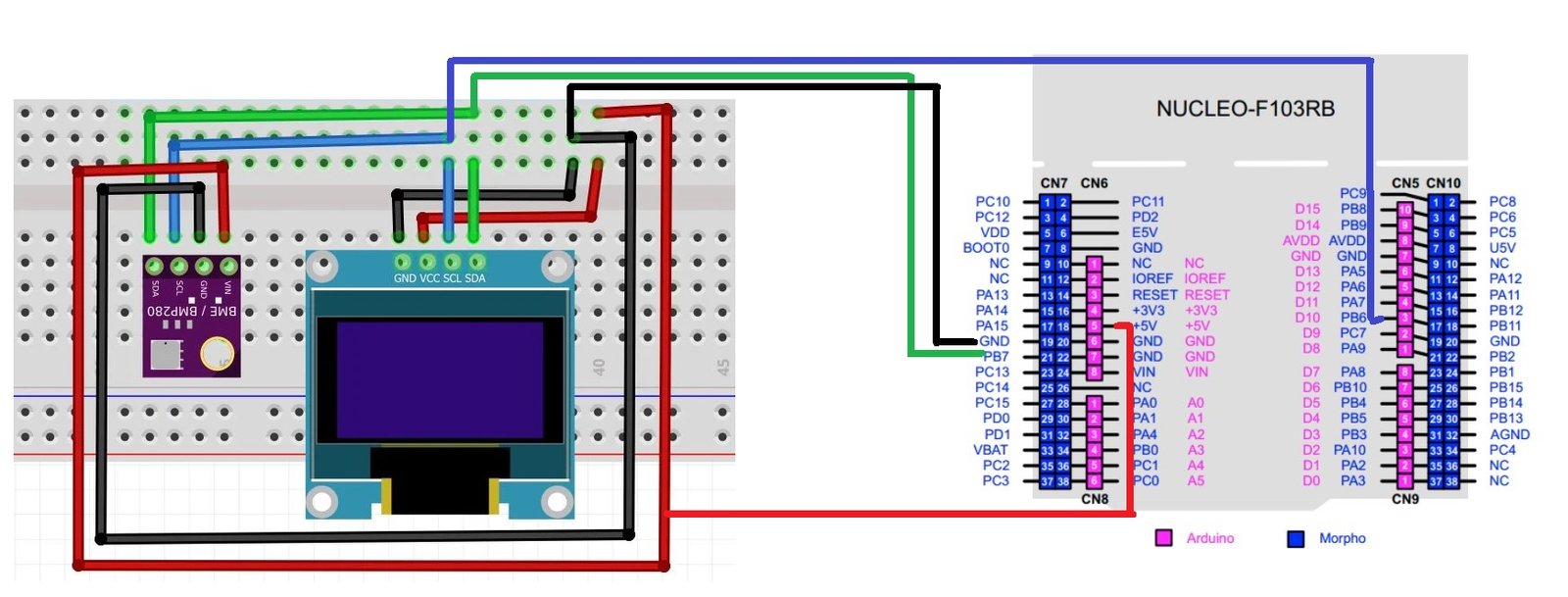
The connections between the three devices which we are using can be seen below.
The connections between the OLED and Nucleo can be seen below.
| STM32 Nucleo | BME280 | SSD1306 OLED Display |
|---|---|---|
| 5V | VIN | VCC |
| PB7 (I2C1_SDA) | SDA | SDA |
| PB6 (I2C_SCL) | SCL | SCL |
| GND | GND | GND |
Connect the BME280 sensor and OLED with STM32 Nucleo as shown in the schematic diagram below. We are using the same connections as specified in the tables above.
STM32 Nucleo BME280 Code with OLED
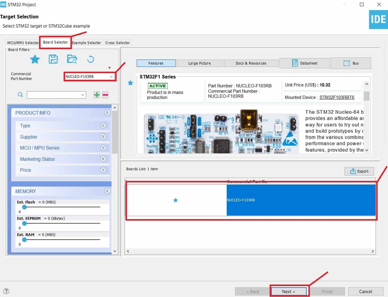
We will use STM32Cube IDE to program our STM32 board. Open the IDE and head over to a new project.
Then for the target selection, specify the STM32 Nucleo board number. After that click on any column as shown in the picture below. Then click the ‘Next’ button.
Specify the name of your project then click ‘Finish’ to complete the setup of your project.
Go to System Core > RCC then select ‘Crystal/Ceramic Resonator’ in from the High Speed Clock feature.
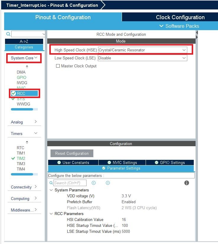
Now we have enabled the RCC external clock source.
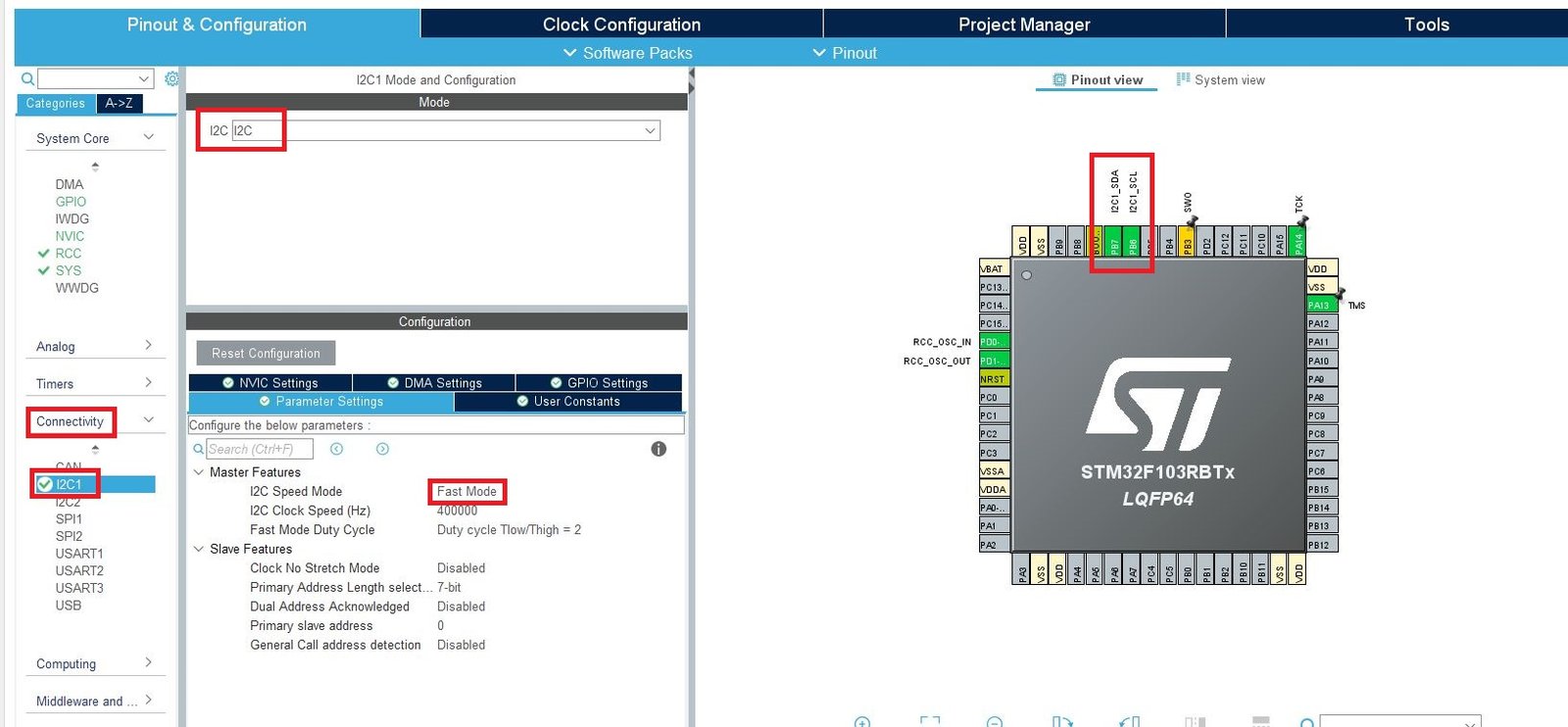
Head over to Connectivity > I2C1. Select the I2C mode as ‘I2C.’ Then go to ‘Parameter Settings’ and set the I2C speed mode as ‘Fast Mode.’ This is necessary for the SSD1306 OLED.
Now we will save our file. Press Ctrl + S. The following window will appear. Click ‘Yes.’ This will generate a template code for you.

Another window will appear that will ask if you want to open the perspective. Click ‘Yes.’

STM32 BME280 Library
To acquire BME280 temperature, pressure, and humidity readings with STM32 Nucleo using STMCube IDE, we will require some BME280 libraries. Let us show you how to include them in your project in order to access the APIs provided by bme280.h
Create a new folder called BME280 inside the Src folder. Copy and save the following files inside the BME280 folder.
STM32 OLED Library
As we are working with an SSD1306 OLED with our STM32 Nucleo, we will require the ssd1306.h and fonts.h libraries. These libraries will be used to access different functions that will enable us to display texts and numbers on the OLED in various ways.
ssd1306.h
Go to Core > Inc and create a new file called ‘ssd1306.h‘ Copy the following code from this link and save it to this file.
In ssd1306.h file, remove #include “i2c.h” (line 49) and add extern I2C_HandleTypeDef hi2c1;
fonts.h
Go to Core > Inc and create a new file called ‘fonts.h‘ Copy the following code from this link and save it to this file.
ssd1306.c
Similarly, head over to Core > Src and create a new file called ‘ssd1306.c‘ Copy the following code from this link and save it to this file.
fonts.c
Head over to Core > Src and create a new file called ‘fonts.c‘ Copy the following code from this link and save it to this file.
STM32 Nucleo BME280 Sensor Code STM32CubeIDE
Now let us look at our main.c file that was generated. Inside the main.c file, make sure the following code is part of your script by including the lines of code given below. We will use bme280.h library functions to access the BME280 sensor data and display them on the OLED using the fonts.h and ssd1306.h APIs.
#include <stdio.h>
#include <string.h>
#include "./BME280/bme280.h"
#include "fonts.h"
#include "ssd1306.h"
I2C_HandleTypeDef hi2c1;
void SystemClock_Config(void);
static void MX_GPIO_Init(void);
static void MX_I2C1_Init(void);
float temperature;
float humidity;
float pressure;

struct bme280_dev dev;
struct bme280_data comp_data;
int8_t rslt;

char hum_string[50];
char temp_string[50];
char press_string[50];
int8_t user_i2c_read(uint8_t id, uint8_t reg_addr, uint8_t *data, uint16_t len)
{
if(HAL_I2C_Master_Transmit(&hi2c1, (id << 1), ®_addr, 1, 10) != HAL_OK) return -1;
if(HAL_I2C_Master_Receive(&hi2c1, (id << 1) | 0x01, data, len, 10) != HAL_OK) return -1;
return 0;
}
void user_delay_ms(uint32_t period)
{
  HAL_Delay(period);
}
int8_t user_i2c_write(uint8_t id, uint8_t reg_addr, uint8_t *data, uint16_t len)
{
  int8_t *buf;
  buf = malloc(len +1);
  buf[0] = reg_addr;
  memcpy(buf +1, data, len);

  if(HAL_I2C_Master_Transmit(&hi2c1, (id << 1), (uint8_t*)buf, len + 1, HAL_MAX_DELAY) != HAL_OK) return -1;

  free(buf);
  return 0;
}
int main(void)
{
HAL_Init();
  SystemClock_Config();
  MX_GPIO_Init();
  MX_I2C1_Init();
/* BME280 init */
dev.dev_id = BME280_I2C_ADDR_PRIM;
  dev.intf = BME280_I2C_INTF;
  dev.read = user_i2c_read;
  dev.write = user_i2c_write;
  dev.delay_ms = user_delay_ms;

  rslt = bme280_init(&dev);
/* BME280 settings */
  dev.settings.osr_h = BME280_OVERSAMPLING_1X;
  dev.settings.osr_p = BME280_OVERSAMPLING_16X;
  dev.settings.osr_t = BME280_OVERSAMPLING_2X;
  dev.settings.filter = BME280_FILTER_COEFF_16;
  rslt = bme280_set_sensor_settings(BME280_OSR_PRESS_SEL | BME280_OSR_TEMP_SEL | BME280_OSR_HUM_SEL | BME280_FILTER_SEL, &dev);
/* Initialize OLED*/
SSD1306_Init();
while (1)
{
/* Forced mode setting, switched to SLEEP mode after measurement */
  rslt = bme280_set_sensor_mode(BME280_FORCED_MODE, &dev);
   dev.delay_ms(40);
/*Get Data */
rslt = bme280_get_sensor_data(BME280_ALL, &comp_data, &dev);
 if(rslt == BME280_OK)
    {
      temperature = comp_data.temperature / 100.0;
      humidity = comp_data.humidity / 1024.0;
      pressure = comp_data.pressure / 10000.0;

      /*Display Data */
      memset(hum_string, 0, sizeof(hum_string));
      memset(temp_string, 0, sizeof(temp_string));
      memset(press_string, 0, sizeof(press_string));

      sprintf(hum_string, "Humidity %03.1f %% ", humidity);
      sprintf(temp_string, "Temperature %03.1f C ", temperature);
      sprintf(press_string, "Pressure %03.1f hPa ", pressure);

      SSD1306_GotoXY (0, 0);
      SSD1306_Puts (hum_string, &Font_7x10, 1);
      SSD1306_GotoXY (0, 20);
      SSD1306_Puts (temp_string, &Font_7x10, 1);
      SSD1306_GotoXY (0, 40);
      SSD1306_Puts (press_string, &Font_7x10, 1);
      SSD1306_UpdateScreen();
    }
HAL_Delay(1000);
}
}How does the Code Work?
We start off by including the necessary libraries for this project which include the bme280.h for the sensor and fonts.h and ssd1306.h for the OLED functionality.
#include <stdio.h>
#include <string.h>
#include "./BME280/bme280.h"
#include "fonts.h"
#include "ssd1306.h"Create some variables that we will use later on in the sketch to store the BME280 sensor data.
float temperature;
float humidity;
float pressure;
struct bme280_dev dev;
struct bme280_data comp_data;
int8_t rslt;
char hum_string[50];
char temp_string[50];
char press_string[50];The user_i2c_read() function calls the data transmission and reception I2C HAL APIs in blocking mode for read purpose. This function returns 0 if I2C read data transmission and reception for master occurs successfully. Otherwise, if either of them fails, -1 is returned instead.
int8_t user_i2c_read(uint8_t id, uint8_t reg_addr, uint8_t *data, uint16_t len)
{
if(HAL_I2C_Master_Transmit(&hi2c1, (id << 1), ®_addr, 1, 10) != HAL_OK) return -1;
if(HAL_I2C_Master_Receive(&hi2c1, (id << 1) | 0x01, data, len, 10) != HAL_OK) return -1;
return 0;
}The user_delay_ms() function takes in a single parameter which is ‘period’ inside it. This function will be called to cause a delay according to the period set.
void user_delay_ms(uint32_t period)
{
HAL_Delay(period);
}The user_i2c_write() function calls the data transmission I2C HAL APIs in blocking mode for write purpose. This function returns 0 if I2C write data transmission for master occurs successfully. Otherwise, -1 is returned instead.
int8_t user_i2c_write(uint8_t id, uint8_t reg_addr, uint8_t *data, uint16_t len)
{
int8_t *buf;
buf = malloc(len +1);
buf[0] = reg_addr;
memcpy(buf +1, data, len);
if(HAL_I2C_Master_Transmit(&hi2c1, (id << 1), (uint8_t*)buf, len + 1, HAL_MAX_DELAY) != HAL_OK) return -1;
free(buf);
return 0;
}main()
Inside the main function, first all the peripherals are initialized, system clock is configured and all the configured peripherals are initialized.
HAL_Init();
SystemClock_Config();
MX_GPIO_Init();
MX_I2C1_Init();Initialize BME280 Sensor
Specify the BME280 device structure parameters for initialization including device id, interface, read function pointer, write function pointer and delay function pointer. Initialize the BME280 sensor by calling bme280_init() which reads the chip-id and calibrates data from the sensor. This function takes in a single parameter which is the pointer to the bme280 device structure.
dev.dev_id = BME280_I2C_ADDR_PRIM;
dev.intf = BME280_I2C_INTF;
dev.read = user_i2c_read;
dev.write = user_i2c_write;
dev.delay_ms = user_delay_ms;
rslt = bme280_init(&dev);Next, we set the settings of the BME280 sensor which includes the humidity, pressure and temperature oversampling values. The function bme280_set_sensor_settings() is responsible for setting the oversampling, filter, and standby duration. It takes in two parameters which are the desired settings and the pointer to the bme280 device structure.
dev.settings.osr_h = BME280_OVERSAMPLING_1X;
dev.settings.osr_p = BME280_OVERSAMPLING_16X;
dev.settings.osr_t = BME280_OVERSAMPLING_2X;
dev.settings.filter = BME280_FILTER_COEFF_16;
rslt = bme280_set_sensor_settings(BME280_OSR_PRESS_SEL | BME280_OSR_TEMP_SEL | BME280_OSR_HUM_SEL | BME280_FILTER_SEL, &dev);Moreover, we initialize the OLED by calling SSD1306_Init() function for initialization.
SSD1306_Init();Obtain Sensor Data
Inside the infinite while loop, we first set the BME280 sensor in forced mode setting and then switch it to sleep mode after the measurement. The mode of the sensor is configured through the function bme280_set_sensor_mode().
rslt = bme280_set_sensor_mode(BME280_FORCED_MODE, &dev);
dev.delay_ms(40);After a short delay, we will start accessing the sensor data from the sensor. The bme280_get_sensor_data() will read the temperature, pressure and humidity readings from the BME280 sensor, compensate them and store them in the bme280_data structure.
rslt = bme280_get_sensor_data(BME280_ALL, &comp_data, &dev);Display Sensor Data
If the function returns a successful response, then we will start displaying the sensor readings on the OLED screen. The readings will update to new values after every second.
if(rslt == BME280_OK)
{
   temperature = comp_data.temperature / 100.0;
      humidity = comp_data.humidity / 1024.0;
      pressure = comp_data.pressure / 10000.0;
/*Display Data */
      memset(hum_string, 0, sizeof(hum_string));
      memset(temp_string, 0, sizeof(temp_string));
      memset(press_string, 0, sizeof(press_string));

      sprintf(hum_string, "Humidity %03.1f %% ", humidity);
      sprintf(temp_string, "Temperature %03.1f C ", temperature);
      sprintf(press_string, "Pressure %03.1f hPa ", pressure);

      SSD1306_GotoXY (0, 0);
      SSD1306_Puts (hum_string, &Font_7x10, 1);
      SSD1306_GotoXY (0, 20);
      SSD1306_Puts (temp_string, &Font_7x10, 1);
      SSD1306_GotoXY (0, 40);
      SSD1306_Puts (press_string, &Font_7x10, 1);
      SSD1306_UpdateScreen();
}
First of all, we will obtain individual compensated temperature readings in degree Celsius, compensated humidity readings in percentage and compensated pressure readings in hPa from the bme_280 structure.
temperature = comp_data.temperature / 100.0;
humidity = comp_data.humidity / 1024.0;
pressure = comp_data.pressure / 10000.0;Then we convert the float variables to strings consisting of readings and units and display them on the OLED.
To display the sensor data on the OLED, first, we will set the x and the y axis position from where the text should start. SSD1306_gotoXY() function is used to set the write pointers. We have passed (0,0) as the parameter hence the text starts from the upper left corner. We use SSD1306_Puts() function to display the humidity readings along with its unit on the screen. This function takes in three parameters which is the string to be displayed, the font name and the color of the text. Similarly, to display temperature and pressure readings, we first set the starting x-axis and y-axis at (0,20) and (0,40) respectively and then call SSD1306_Puts() to display the strings. Additionally, call SSD1306_UpdateScreen() to display the text on the screen.
memset(hum_string, 0, sizeof(hum_string));
memset(temp_string, 0, sizeof(temp_string));
memset(press_string, 0, sizeof(press_string));
sprintf(hum_string, "Humidity %03.1f %% ", humidity);
sprintf(temp_string, "Temperature %03.1f C ", temperature);
sprintf(press_string, "Pressure %03.1f hPa ", pressure);
SSD1306_GotoXY (0, 0);
SSD1306_Puts (hum_string, &Font_7x10, 1);
SSD1306_GotoXY (0, 20);
SSD1306_Puts (temp_string, &Font_7x10, 1);
SSD1306_GotoXY (0, 40);
SSD1306_Puts (press_string, &Font_7x10, 1);
SSD1306_UpdateScreen();main.c file
This is how a complete main.c file will be after modification.
/* USER CODE BEGIN Header */
/**
******************************************************************************
* @file : main.c
* @brief : Main program body
******************************************************************************
* @attention
*
* Copyright (c) 2024 STMicroelectronics.
* All rights reserved.
*
* This software is licensed under terms that can be found in the LICENSE file
* in the root directory of this software component.
* If no LICENSE file comes with this software, it is provided AS-IS.
*
******************************************************************************
*/
/* USER CODE END Header */
/* Includes ------------------------------------------------------------------*/
#include "main.h"
/* Private includes ----------------------------------------------------------*/
/* USER CODE BEGIN Includes */
extern I2C_HandleTypeDef hi2c1;
#include "fonts.h"
#include "ssd1306.h"
#include <stdio.h>
#include "./BME280/bme280.h"
#include <string.h>
/* USER CODE END Includes */
/* Private typedef -----------------------------------------------------------*/
/* USER CODE BEGIN PTD */
/* USER CODE END PTD */
/* Private define ------------------------------------------------------------*/
/* USER CODE BEGIN PD */
/* USER CODE END PD */
/* Private macro -------------------------------------------------------------*/
/* USER CODE BEGIN PM */
/* USER CODE END PM */
/* Private variables ---------------------------------------------------------*/
I2C_HandleTypeDef hi2c1;
TIM_HandleTypeDef htim1;
/* USER CODE BEGIN PV */
float temperature;
float humidity;
float pressure;
struct bme280_dev dev;
struct bme280_data comp_data;
int8_t rslt;
char hum_string[50];
char temp_string[50];
char press_string[50];
int8_t user_i2c_read(uint8_t id, uint8_t reg_addr, uint8_t *data, uint16_t len)
{
if(HAL_I2C_Master_Transmit(&hi2c1, (id << 1), ®_addr, 1, 10) != HAL_OK) return -1;
if(HAL_I2C_Master_Receive(&hi2c1, (id << 1) | 0x01, data, len, 10) != HAL_OK) return -1;
return 0;
}
void user_delay_ms(uint32_t period)
{
HAL_Delay(period);
}
int8_t user_i2c_write(uint8_t id, uint8_t reg_addr, uint8_t *data, uint16_t len)
{
int8_t *buf;
buf = malloc(len +1);
buf[0] = reg_addr;
memcpy(buf +1, data, len);
if(HAL_I2C_Master_Transmit(&hi2c1, (id << 1), (uint8_t*)buf, len + 1, HAL_MAX_DELAY) != HAL_OK) return -1;
free(buf);
return 0;
}
/* USER CODE END PV */
/* Private function prototypes -----------------------------------------------*/
void SystemClock_Config(void);
static void MX_GPIO_Init(void);
static void MX_I2C1_Init(void);
static void MX_TIM1_Init(void);
/* USER CODE BEGIN PFP */
/* USER CODE END PFP */
/* Private user code ---------------------------------------------------------*/
/* USER CODE BEGIN 0 */
/* USER CODE END 0 */
/**
* @brief The application entry point.
* @retval int
*/
int main(void)
{
/* USER CODE BEGIN 1 */
/* USER CODE END 1 */
/* MCU Configuration--------------------------------------------------------*/
/* Reset of all peripherals, Initializes the Flash interface and the Systick. */
HAL_Init();
/* USER CODE BEGIN Init */
/* USER CODE END Init */
/* Configure the system clock */
SystemClock_Config();
/* USER CODE BEGIN SysInit */
/* USER CODE END SysInit */
/* Initialize all configured peripherals */
MX_GPIO_Init();
MX_I2C1_Init();
MX_TIM1_Init();
/* USER CODE BEGIN 2 */
HAL_TIM_Base_Start(&htim1);
/* BME280 init */
dev.dev_id = BME280_I2C_ADDR_PRIM;
dev.intf = BME280_I2C_INTF;
dev.read = user_i2c_read;
dev.write = user_i2c_write;
dev.delay_ms = user_delay_ms;
rslt = bme280_init(&dev);
/* BME280 settings */
dev.settings.osr_h = BME280_OVERSAMPLING_1X;
dev.settings.osr_p = BME280_OVERSAMPLING_16X;
dev.settings.osr_t = BME280_OVERSAMPLING_2X;
dev.settings.filter = BME280_FILTER_COEFF_16;
rslt = bme280_set_sensor_settings(BME280_OSR_PRESS_SEL | BME280_OSR_TEMP_SEL | BME280_OSR_HUM_SEL | BME280_FILTER_SEL, &dev);
/* Initialize OLED*/
SSD1306_Init();
/* USER CODE END 2 */
/* Infinite loop */
/* USER CODE BEGIN WHILE */
while (1)
{
/* Forced mode setting, switched to SLEEP mode after measurement */
rslt = bme280_set_sensor_mode(BME280_FORCED_MODE, &dev);
dev.delay_ms(40);
/*Get Data */
rslt = bme280_get_sensor_data(BME280_ALL, &comp_data, &dev);
if(rslt == BME280_OK)
{
temperature = comp_data.temperature / 100.0;
humidity = comp_data.humidity / 1024.0;
pressure = comp_data.pressure / 10000.0;
/*Display Data */
memset(hum_string, 0, sizeof(hum_string));
memset(temp_string, 0, sizeof(temp_string));
memset(press_string, 0, sizeof(press_string));
sprintf(hum_string, "Humidity %03.1f %% ", humidity);
sprintf(temp_string, "Temperature %03.1f C ", temperature);
sprintf(press_string, "Pressure %03.1f hPa ", pressure);
SSD1306_GotoXY (0, 0);
SSD1306_Puts (hum_string, &Font_7x10, 1);
SSD1306_GotoXY (0, 20);
SSD1306_Puts (temp_string, &Font_7x10, 1);
SSD1306_GotoXY (0, 40);
SSD1306_Puts (press_string, &Font_7x10, 1);
SSD1306_UpdateScreen();
}
HAL_Delay(1000);
/* USER CODE END WHILE */
/* USER CODE BEGIN 3 */
}
/* USER CODE END 3 */
}
/**
* @brief System Clock Configuration
* @retval None
*/
void SystemClock_Config(void)
{
RCC_OscInitTypeDef RCC_OscInitStruct = {0};
RCC_ClkInitTypeDef RCC_ClkInitStruct = {0};
/** Initializes the RCC Oscillators according to the specified parameters
* in the RCC_OscInitTypeDef structure.
*/
RCC_OscInitStruct.OscillatorType = RCC_OSCILLATORTYPE_HSE;
RCC_OscInitStruct.HSEState = RCC_HSE_ON;
RCC_OscInitStruct.HSEPredivValue = RCC_HSE_PREDIV_DIV1;
RCC_OscInitStruct.HSIState = RCC_HSI_ON;
RCC_OscInitStruct.PLL.PLLState = RCC_PLL_ON;
RCC_OscInitStruct.PLL.PLLSource = RCC_PLLSOURCE_HSE;
RCC_OscInitStruct.PLL.PLLMUL = RCC_PLL_MUL9;
if (HAL_RCC_OscConfig(&RCC_OscInitStruct) != HAL_OK)
{
Error_Handler();
}
/** Initializes the CPU, AHB and APB buses clocks
*/
RCC_ClkInitStruct.ClockType = RCC_CLOCKTYPE_HCLK|RCC_CLOCKTYPE_SYSCLK
|RCC_CLOCKTYPE_PCLK1|RCC_CLOCKTYPE_PCLK2;
RCC_ClkInitStruct.SYSCLKSource = RCC_SYSCLKSOURCE_PLLCLK;
RCC_ClkInitStruct.AHBCLKDivider = RCC_SYSCLK_DIV1;
RCC_ClkInitStruct.APB1CLKDivider = RCC_HCLK_DIV2;
RCC_ClkInitStruct.APB2CLKDivider = RCC_HCLK_DIV1;
if (HAL_RCC_ClockConfig(&RCC_ClkInitStruct, FLASH_LATENCY_2) != HAL_OK)
{
Error_Handler();
}
}
/**
* @brief I2C1 Initialization Function
* @param None
* @retval None
*/
static void MX_I2C1_Init(void)
{
/* USER CODE BEGIN I2C1_Init 0 */
/* USER CODE END I2C1_Init 0 */
/* USER CODE BEGIN I2C1_Init 1 */
/* USER CODE END I2C1_Init 1 */
hi2c1.Instance = I2C1;
hi2c1.Init.ClockSpeed = 400000;
hi2c1.Init.DutyCycle = I2C_DUTYCYCLE_2;
hi2c1.Init.OwnAddress1 = 0;
hi2c1.Init.AddressingMode = I2C_ADDRESSINGMODE_7BIT;
hi2c1.Init.DualAddressMode = I2C_DUALADDRESS_DISABLE;
hi2c1.Init.OwnAddress2 = 0;
hi2c1.Init.GeneralCallMode = I2C_GENERALCALL_DISABLE;
hi2c1.Init.NoStretchMode = I2C_NOSTRETCH_DISABLE;
if (HAL_I2C_Init(&hi2c1) != HAL_OK)
{
Error_Handler();
}
/* USER CODE BEGIN I2C1_Init 2 */
/* USER CODE END I2C1_Init 2 */
}
/**
* @brief TIM1 Initialization Function
* @param None
* @retval None
*/
static void MX_TIM1_Init(void)
{
/* USER CODE BEGIN TIM1_Init 0 */
/* USER CODE END TIM1_Init 0 */
TIM_ClockConfigTypeDef sClockSourceConfig = {0};
TIM_MasterConfigTypeDef sMasterConfig = {0};
/* USER CODE BEGIN TIM1_Init 1 */
/* USER CODE END TIM1_Init 1 */
htim1.Instance = TIM1;
htim1.Init.Prescaler = 71;
htim1.Init.CounterMode = TIM_COUNTERMODE_UP;
htim1.Init.Period = 65534;
htim1.Init.ClockDivision = TIM_CLOCKDIVISION_DIV1;
htim1.Init.RepetitionCounter = 0;
htim1.Init.AutoReloadPreload = TIM_AUTORELOAD_PRELOAD_DISABLE;
if (HAL_TIM_Base_Init(&htim1) != HAL_OK)
{
Error_Handler();
}
sClockSourceConfig.ClockSource = TIM_CLOCKSOURCE_INTERNAL;
if (HAL_TIM_ConfigClockSource(&htim1, &sClockSourceConfig) != HAL_OK)
{
Error_Handler();
}
sMasterConfig.MasterOutputTrigger = TIM_TRGO_RESET;
sMasterConfig.MasterSlaveMode = TIM_MASTERSLAVEMODE_DISABLE;
if (HAL_TIMEx_MasterConfigSynchronization(&htim1, &sMasterConfig) != HAL_OK)
{
Error_Handler();
}
/* USER CODE BEGIN TIM1_Init 2 */
/* USER CODE END TIM1_Init 2 */
}
/**
* @brief GPIO Initialization Function
* @param None
* @retval None
*/
static void MX_GPIO_Init(void)
{
/* USER CODE BEGIN MX_GPIO_Init_1 */
/* USER CODE END MX_GPIO_Init_1 */
/* GPIO Ports Clock Enable */
__HAL_RCC_GPIOD_CLK_ENABLE();
__HAL_RCC_GPIOA_CLK_ENABLE();
__HAL_RCC_GPIOB_CLK_ENABLE();
/* USER CODE BEGIN MX_GPIO_Init_2 */
/* USER CODE END MX_GPIO_Init_2 */
}
/* USER CODE BEGIN 4 */
/* USER CODE END 4 */
/**
* @brief This function is executed in case of error occurrence.
* @retval None
*/
void Error_Handler(void)
{
/* USER CODE BEGIN Error_Handler_Debug */
/* User can add his own implementation to report the HAL error return state */
__disable_irq();
while (1)
{
}
/* USER CODE END Error_Handler_Debug */
}
#ifdef USE_FULL_ASSERT
/**
* @brief Reports the name of the source file and the source line number
* where the assert_param error has occurred.
* @param file: pointer to the source file name
* @param line: assert_param error line source number
* @retval None
*/
void assert_failed(uint8_t *file, uint32_t line)
{
/* USER CODE BEGIN 6 */
/* User can add his own implementation to report the file name and line number,
ex: printf("Wrong parameters value: file %s on line %d\r\n", file, line) */
/* USER CODE END 6 */
}
#endif /* USE_FULL_ASSERT */
Save the main.c file after modifying it. Now we are ready to build our project.
Building the Project
To build our project press Ctrl + B or go to Project > Build All.
Your project will start building. After a few moments, your project will be successfully built if there are no errors.
Demonstration
Next press the RUN button in the IDE. The ‘Edit configuration’ window will open up. Click ‘OK’.
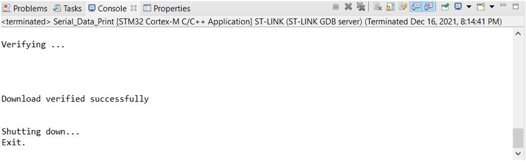
After a few moments, the code will be successfully sent to the STM32 board.
Otherwise, press the RESET button on your STM32
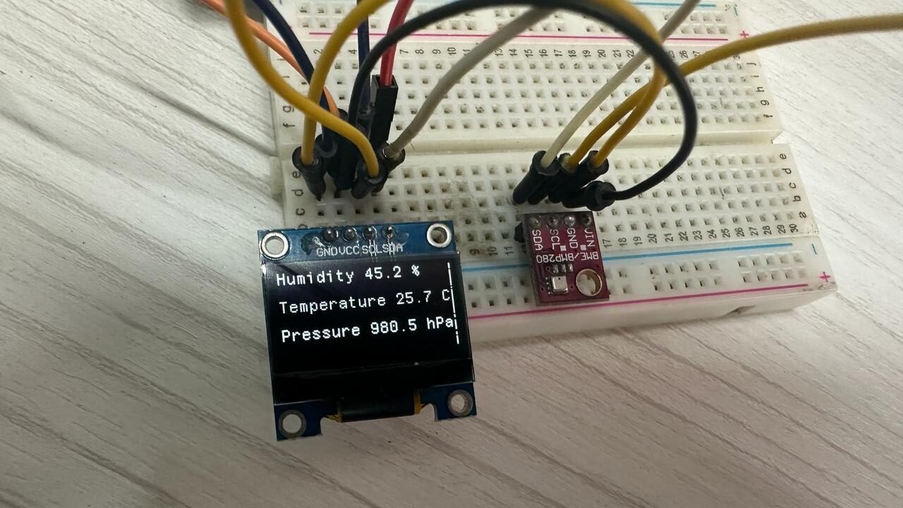
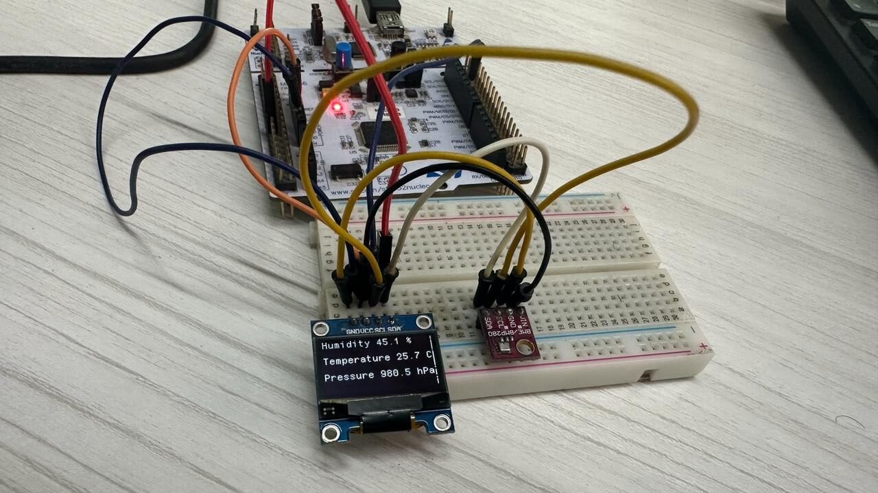
Once the code is uploaded to the board, the OLED will start displaying the humidity, temperature, and pressure readings on the screen, which will update to new values after every second.
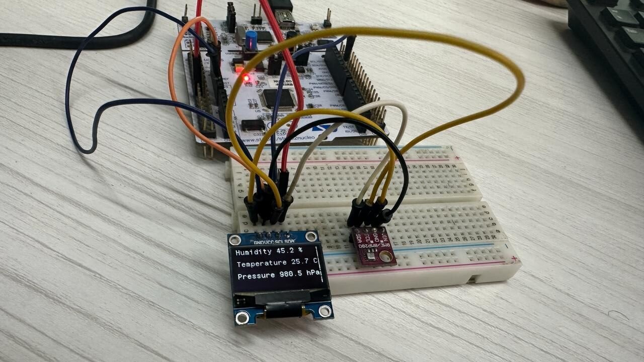
Demo:
You may also like to read:
- I2C LCD with STM32 Nucleo using STM32CubeIDE
- HC-SR04 Ultrasonic Sensor with STM32 Nucleo using STM32CubeIDE
- SSD1306 OLED with STM32 Nucleo using STM32CubeIDE
- HC-05 Bluetooth Module with STM32 Nucleo using STM32CubeIDE
- STM32 Nucleo Timer in Counter Mode with STM32CubeIDE and HAL Libraries
Other projects with BME280:
- BME280 Web Server with ESP32 (Arduino IDE)
- Telegram ESP32/ESP8266: Display BME280 sensor readings using Arduino IDE
- ESP32 Send Sensor Readings to ThingSpeak using Arduino IDE (BME280)
- ESP32 ESP8266 MicroPython MQTT Publish BME280 Readings to Node-RED
- ESP32 MQTT Publish Subscribe BME280 Readings with Arduino IDE
- ESP32 Send BME280 Sensor Readings to InfluxDB
I put a fuel sensor in my transport diesel tank. Would like to read the fuel level on my iPhone (Bluetooth). The sensor output is in ohm’s. Can you help?