In this user guide, we will learn to interface the BME280 with ESP8266 NodeMCU which is used to pressure, humidity, and temperature using Arduino IDE. Firstly, we will learn about BME280 and how to connect with ESP8266 NodeMCU. Secondly, we will see how to install the BME280 library in Arduino IDE. Next, we will work on a simple Arduino example to demonstrate its working and lastly, we will measure Temperature, Humidity, and Pressure and display them on a serial monitor and SSD1306 OLED.
We have a similar guide with MicroPython:
MicroPython: BME280 with ESP32 and ESP8266
We will cover the following topics in this article:
- Interface BME280 with ESP8266 NodeMCU
- Display Sensor readings on Arduino serial monitor
- Print Sensor readings on SSD1306 OLED
We also have a similar guide with ESP32 using Arduino IDE:
BME280 with ESP32 – Display Values on OLED ( Arduino IDE)
BME280 Introduction
The BME280 sensor is used to measure readings regarding ambient temperature, barometric pressure, and relative humidity. It is mostly used in web and mobile applications where low power consumption is key. This sensor uses I2C or SPI to communicate data with the micro-controllers. Although there are several different versions of BME280 available in the market, the one we will be studying uses the I2C communication protocol and SPI.
I2C means Inter-Integrated Circuit and works on the principle of the synchronous, multi-master multi-slave system. With BME280 and the ESP boards, the ESP8266 NodeMCU acts as a master, and the BME280 sensor as a slave because it is an external device, acts as a slave. The ESP development boards communicate with the BME280 sensor through the I2C protocol to get temperature, barometric pressure, and relative humidity.
Pinout Diagram
The figure below shows the BME280 sensor and its pinout.
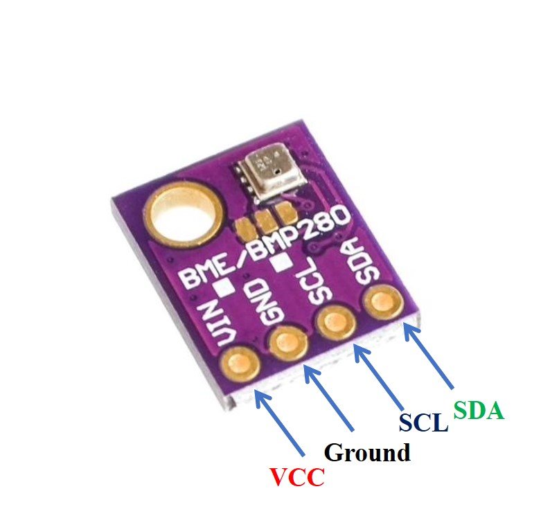
- VCC: connected with 3.3V
- SCL: used to generate the clock signal
- SDA: used in sending and receiving data
ESP8266 NodeMCU Schematic with BME280
The connection of BME280 with the ESP boards is very easy. We should connect the VCC terminal of BME280 with 3.3V of ESP8266 NodeMCU, ground with the ground (common ground), SCL of the sensor with SCL of ESP8266 NodeMCU, and SDA of the sensor with the SDA pin of the ESP module.
The I2C pin in ESP8266 NodeMCU for SDA is GPIO4 and for SCL is GPIO4. The connections between the two devices can be seen below.
| ESP8266 NodeMCU | BME280 |
|---|---|
| VCC=3.3V | Vin |
| GPIO4 (D2) | SDA |
| GPIO5 (D1) | SCL |
| GROUND | GROUND |
ESP8266 NodeMCU I2C Pins
The I2C pins stated above are set in default. If we want to change the GPIO pins we have to set them in code. The diagrams below show the I2C pins of ESP8266 NodeMCU marked with red color rectangles.

For more information on ESP8266 NodeMCU pins, refer to the following article:
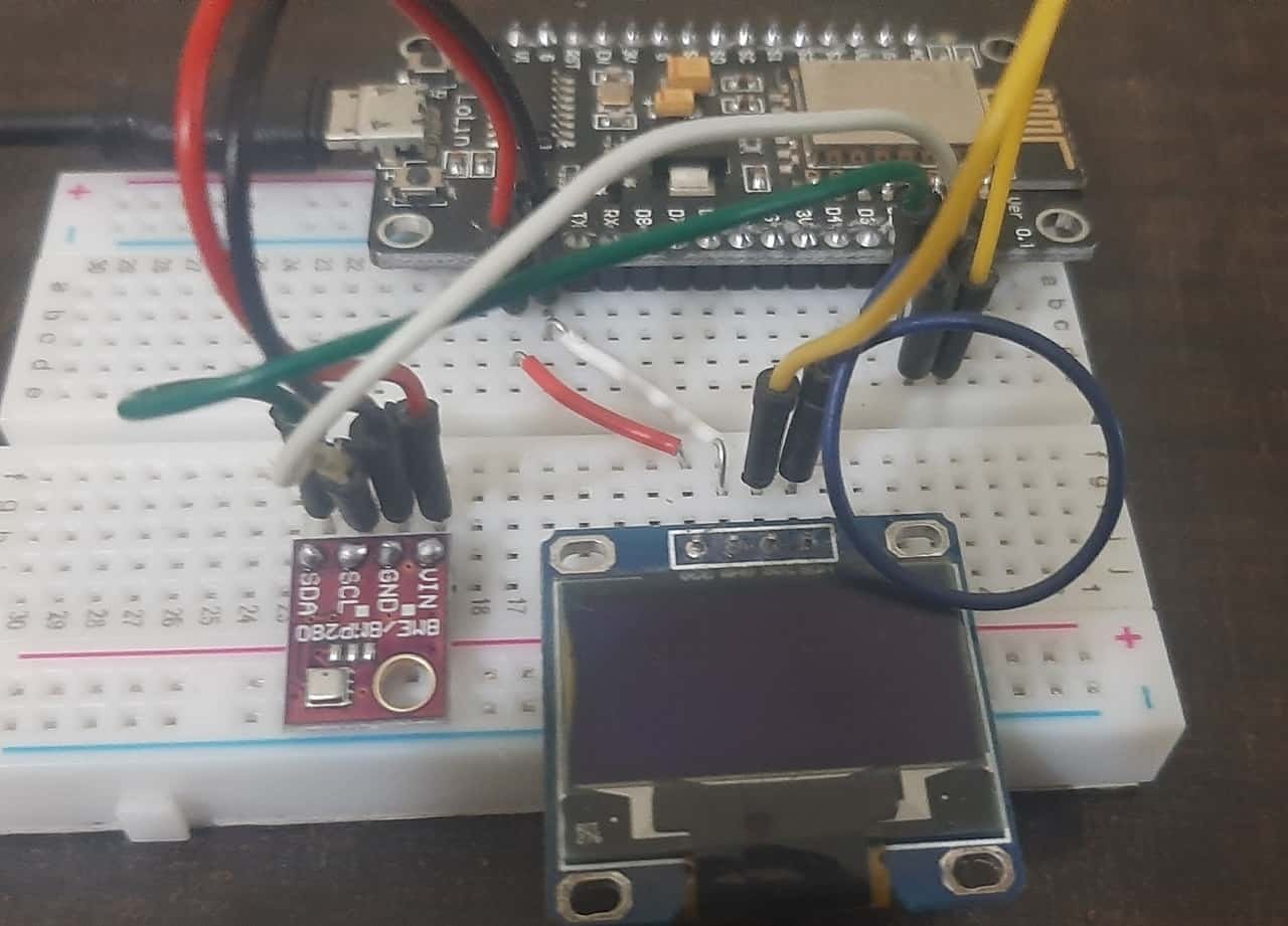
Interfacing BME280 sensor with ESP8266 NodeMCU
The connection of BME280 with the ESP8266 NodeMCU boards is very easy. We have to connect the VCC terminal with 3.3V, ground with the ground (common ground), SCL of the sensor with SCL of the module, and SDA of the sensor with the SDA pin of the ESP module. The I2C pin in ESP8266 NodeMCU for SDA is GPIO4 and for SCL is GPIO5.
Required Components
We will need the following components to connect our ESP8266 NodeMCU board with the BME280 sensor.
- ESP8266 NodeMCU board
- BME280 Sensor
- Connecting Wires
- Breadboard
Follow the schematic diagram below for the ESP8266 NodeMCU module and connect them accordingly.
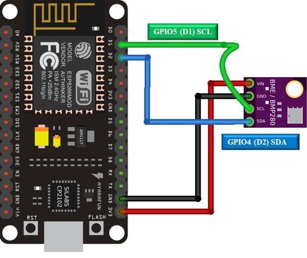
In some BME280 sensors as seen in the above connection diagram, the SCK terminal means the SCL pin and is connected with its respective GPIO pin on the ESP8266 NodeMCU. Likewise, the SDI terminal means the SDA pin and is connected with its respective GPIO pin on the board. Vin is connected with a 3.3V pin on the module and both the ESP board and the BME280 sensor are commonly grounded.
Installing BME280 Arduino Library
We will use Arduino IDE to program our ESP8266 NodeMCUdevelopment board. Thus, you should have the latest version of Arduino IDE. Additionally, you also need to install the ESP8266 NodeMCUplugin. If your IDE does not have the plugins installed you can visit the link below:
Installing ESP8266 library in Arduino IDE and upload code.
As we are connecting the BME280 sensor with ESP8266 NodeMCU so we will have to install BME280 libraries to our module. We will require two libraries for this project:
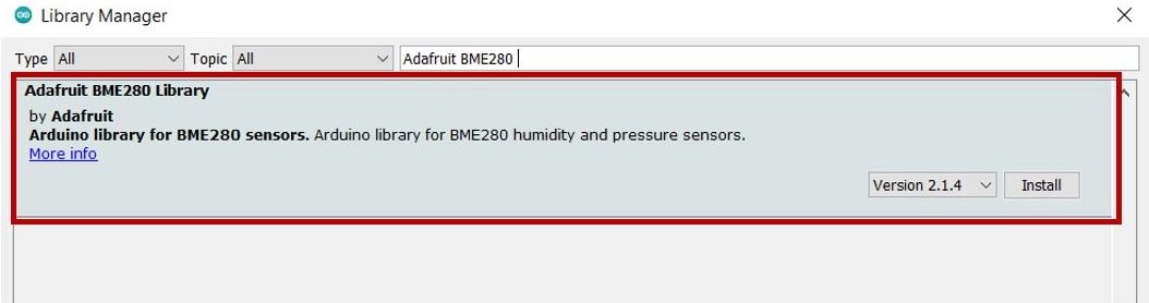
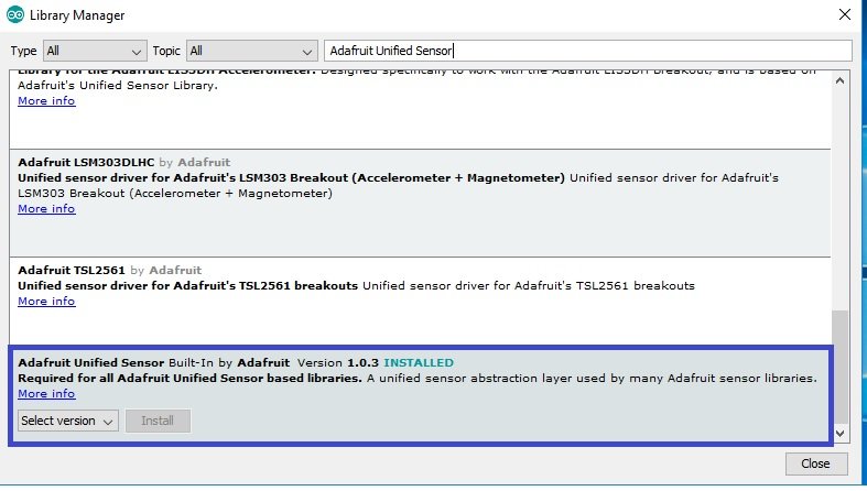
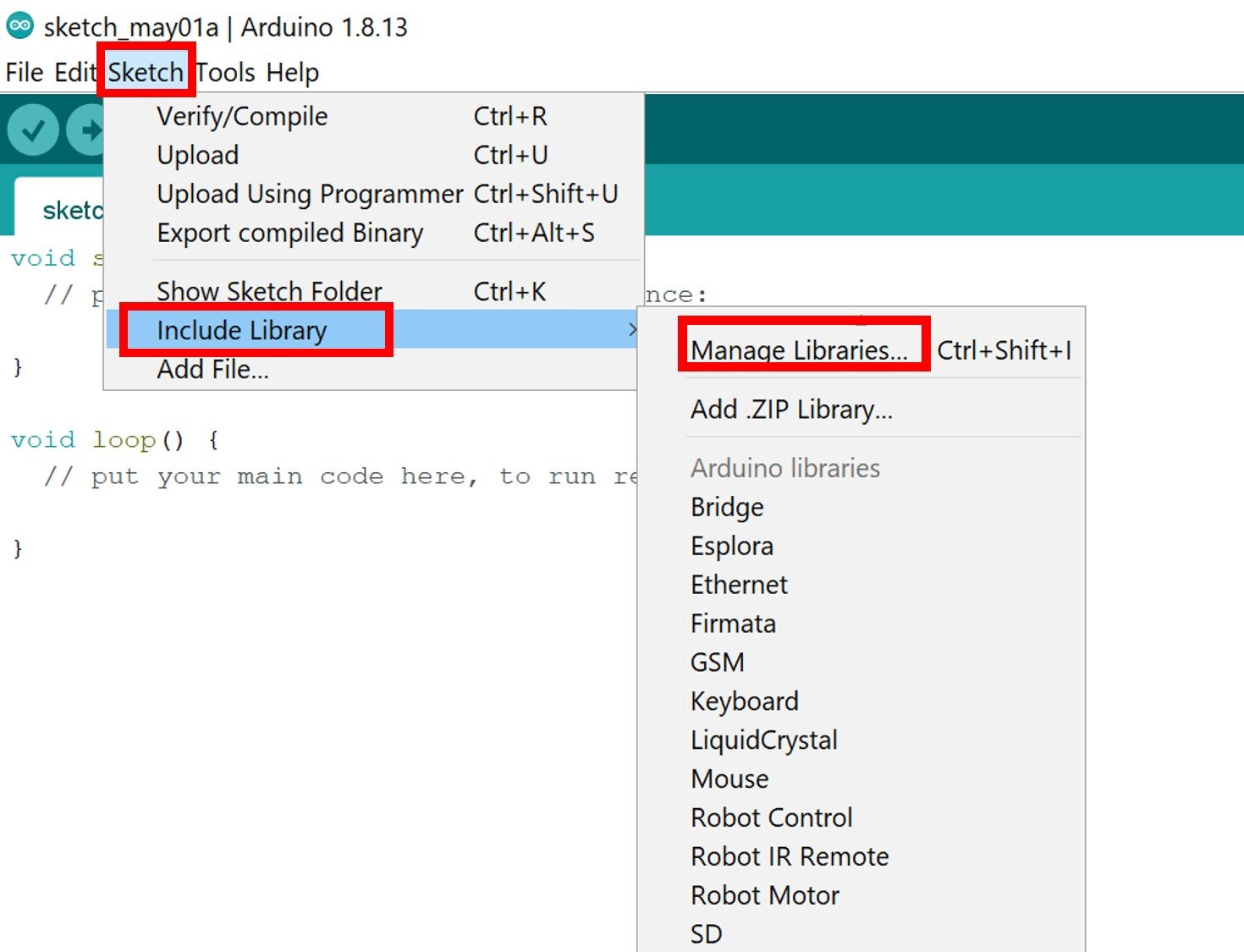
We will use the Library Manager in our Arduino IDE to install the latest versions of the libraries. Open your Arduino IDE and go to Sketch > Include Libraries > Manage Libraries. Type Adafruit BME280 library name in the search bar and install them both.
Open your Arduino IDE and go to Sketch > Include Libraries > Manage Libraries. Type Adafruit unified sensor library name in the search bar and install it.
Arduino Code – Getting BME280 Readings on Arduino Serial Monitor
This BM280 example sketch displays temperature, pressure, approximate altitude, and humidity readings on Arduino serial monitor.
/* Include libraries of BME280 sensor */
#include <Wire.h>
#include <Adafruit_Sensor.h>
#include <Adafruit_BME280.h>

/*#include <SPI.h>  // uncomment his if you are using SPI interface
#define BME_SCK 18
#define BME_MISO 19
#define BME_MOSI 23
#define BME_CS 5*/

#define SEALEVELPRESSURE_HPA (1013.25)

Adafruit_BME280 bme; // I2C
//Adafruit_BME280 bme(BME_CS); // hardware SPI
//Adafruit_BME280 bme(BME_CS, BME_MOSI, BME_MISO, BME_SCK); // software SPI


void setup() {
  Serial.begin(9600);
  Serial.println(F("BME280 test"));

  bool status;

  // default settings
  // (you can also pass in a Wire library object like &Wire2)
  status = bme.begin(0x76);
  if (!status) {
    Serial.println("Could not detect a BME280 sensor, Fix wiring Connections!");
    while (1);
  }

  Serial.println("-- Print BME280 readings--");
  Serial.println();
}


void loop() {
  Serial.print("Temperature = ");
  Serial.print(bme.readTemperature());
  Serial.println(" *C");

  // Convert temperature to Fahrenheit
  /*Serial.print("Temperature = ");
  Serial.print(1.8 * bme.readTemperature() + 32);
  Serial.println(" *F");*/

  Serial.print("Pressure = ");
  Serial.print(bme.readPressure() / 100.0F);
  Serial.println(" hPa");

  Serial.print("Approx. Altitude = ");
  Serial.print(bme.readAltitude(SEALEVELPRESSURE_HPA));
  Serial.println(" m");

  Serial.print("Humidity = ");
  Serial.print(bme.readHumidity());
  Serial.println(" %");

  Serial.println();
  delay(1000);
}
How Code Works?
Now, let us understand how each part of the code works.
Including Libraries
The code starts with including all the necessary libraries which are needed for the proper functionality of the code. The Wire.h will allow us to communicate through the I2C protocol and the SPI.h allows us to communicate through the SPI protocol. Both communication protocols are included. The Adafruit_Sensor and the Adafruit_BME280 libraries which we installed in Arduino IDE earlier are also included as they are necessary to interface with the sensor.
#include <Wire.h>
#include <SPI.h>
#include <Adafruit_BME280.h>
#include <Adafruit_Sensor.h>
This code is using the I2C protocol to communicate with ESP8266 NodeMCU and BME280. If you want to use SPI protocol instead, just uncomment the following block of code which defines the default pins:
/*#define BME_SCK 18
#define BME_MISO 19
#define BME_MOSI 23
#define BME_CS 5*/
Next, the code defines the SEALEVELPRESSURE_HPA by creating a variable by the set name. It takes into account the sea level pressure of your current location and compares it with a given pressure to estimate the altitude. You have to pass your sea-level pressure in hPa according to your location. The 1013.25 is the value that is set in default.
#define SEALEVELPRESSURE_HPA (1013.25)Then, it defines the Adafruit_BME280 object named bme by setting it on the default I2C GPIO pins. If using SPI protocol instead, make sure to comment on this line and uncomment the lines which are initializing the SPI pins.
Adafruit_BME280 bme; // I2C
//Adafruit_BME280 bme(BME_CS); // hardware SPI
//Adafruit_BME280 bme(BME_CS, BME_MOSI, BME_MISO, BME_SCK); // software SPI
The setup() function is created. This initiates the serial communication at a baud rate of 115200 by using the begin() function.
Serial.begin(115200);Then, the BME280 sensor gets initialized and in case of failure, an error message is printed on the serial monitor.
Serial.println(F("BME280 test"));

  bool status;

  // default settings
  // (you can also pass in a Wire library object like &Wire2)
  status = bme.begin(0x76);
  if (!status) {
    Serial.println("Could not detect a BME280 sensor, Fix wiring Connections!");
    while (1);
  }

  Serial.println("-- Print BME280 readings--");
  Serial.println();
Inside the for loop, We take BME280 sensor readings by using bme.readTemperature(), bme.readPressure(), bme.readAltitude(SEALEVELPRESSURE_HPA) and bme.readHumidity() and display them on Arduino serial monitor. These functions measure ambient temperature, barometric pressure, relative humidity, and approximate altitude, respectively. The units are also displayed. The BME280 sensor readings are updated on Arduino serial monitor after every one second.
Serial.print("Temperature = ");
  Serial.print(bme.readTemperature());
  Serial.println(" *C");

  // Convert temperature to Fahrenheit
  /*Serial.print("Temperature = ");
  Serial.print(1.8 * bme.readTemperature() + 32);
  Serial.println(" *F");*/

  Serial.print("Pressure = ");
  Serial.print(bme.readPressure() / 100.0F);
  Serial.println(" hPa");

  Serial.print("Approx. Altitude = ");
  Serial.print(bme.readAltitude(SEALEVELPRESSURE_HPA));
  Serial.println(" m");

  Serial.print("Humidity = ");
  Serial.print(bme.readHumidity());
  Serial.println(" %");

  Serial.println();
  delay(1000);
}
Demonstration
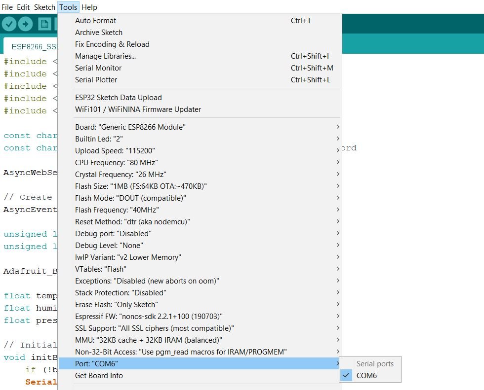
In Arduino IDE, click Tools > Board and select ESP8266 NodeMCU.

Now, click Tools > Port and choose the port which you are using. Now, upload the code by clicking on the upload button.
After you have uploaded the following code on your ESP8266 NodeMCU development board, press the ENABLE button as follows:

In your Arduino IDE, open up the serial monitor and you will see the serial monitor displaying all the BME280 sensor readings such as Pressure, Temperature, Humidity, and altitude as shown below:

Displaying BME280 Sensor values on OLED Display ( Arduino IDE)
In this section, we will see how to display BME280 sensor readings such as Pressure, Temperature, and Humidity values on a 0.96 SSD1306 OLED display using Arduino IDE and ESP8266 NodeMCU.
Installing SSD1306 OLED Library in Arduino IDE
To use the OLED display in our project, we have to install the Adafruit SSD 1306 library in Arduino IDE. Follow the steps below to successfully install it.
Open Arduino IDE and click on Sketch > Library > Manage Libraries
The following window will open up.

Type ‘SSD1306’ in the search tab and install the Adafruit SSD1306 OLED library.

Schematic – OLED with ESP8266 NodeMCU and BME280
The table below shows the terminals of the three devices which should be connected together.
| OLED Display | ESP8266 NodeMCU | BME280 |
|---|---|---|
| VCC | VCC=3.3V | VCC |
| GND | GND | GND |
| SCL | GPIO5 (D1) | SCL |
| SDA | GPIO4 (D2) | SDA |
Assemble the circuit as shown in the schematic diagram below:
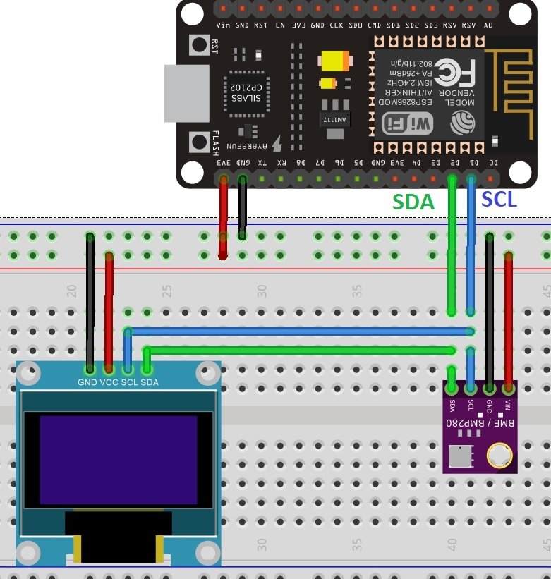
As you can see above, we have connected all the VCC terminals with a 3.3V power supply. The SCL terminals are connected with GPIO22 and the SDA terminals are connected with GPIO21. The grounds are also common.
Arduino Sketch to Display BM280 Readings on OLED
Copy the following code to your Arduino IDE and upload it to the ESP8266 NodeMCU after assembling the above circuit diagram.
#include <Wire.h>
#include <SPI.h>
#include <Adafruit_Sensor.h>
#include <Adafruit_BME280.h>
#include <Adafruit_GFX.h>
#include <Adafruit_SSD1306.h>
/*#include <SPI.h>
#define BME_SCK 18
#define BME_MISO 19
#define BME_MOSI 23
#define BME_CS 5*/

#define SEALEVELPRESSURE_HPA (1013.25)

Adafruit_BME280 bme; // I2C
//Adafruit_BME280 bme(BME_CS); // hardware SPI
//Adafruit_BME280 bme(BME_CS, BME_MOSI, BME_MISO, BME_SCK); // software SPI

Adafruit_SSD1306 display = Adafruit_SSD1306(128, 32, &Wire);
unsigned long delayTime;

void setup() {
  Serial.begin(9600);
  Serial.println(F("BME280 test"));

  // by default, we'll generate the high voltage from the 3.3v line internally! (neat!)
  display.begin(SSD1306_SWITCHCAPVCC, 0x3C);  // initialize with the I2C addr 0x3C (for the 128x64)
   // init done
  display.display();
  delay(100);
  display.clearDisplay();
  display.display();
  display.setTextSize(1.2);
  display.setTextColor(WHITE);

  bool status;
  // default settings
  // (you can also pass in a Wire library object like &Wire2)
  status = bme.begin(0x76);
  if (!status) {
    Serial.println("Could not find a valid BME280 sensor, check wiring!");
    while (1);
  }

  Serial.println("-- Default Test --");
  delayTime = 1000;

  Serial.println();
}


void loop() {

  display.setCursor(0,0);
  display.clearDisplay();

  Serial.print("Temperature = "); Serial.print(bme.readTemperature()); Serial.println(" *C");
  display.print("Temperature: "); display.print(bme.readTemperature()); display.println(" *C");

  Serial.print("Pressure = "); Serial.print(bme.readPressure() / 100.0F); Serial.println(" hPa");
  display.print("Pressure: "); display.print(bme.readPressure() / 100.0F); display.println(" hPa");

  Serial.print("Humidity = "); Serial.print(bme.readHumidity()); Serial.println(" %");
  display.print("Humidity: "); display.print(bme.readHumidity()); display.println(" %");

  Serial.println();
  display.display();
  delay(1000);
}
How Code Works?
The maximum portion of the code is the same as we have discussed earlier except for the OLED display part. Therefore, we will only explain the OLED display part here.
Include Libraries
We will first include all the required libraries for the BME280 sensor as well as the OLED display which we just installed before.
#include <Wire.h>
#include <SPI.h>
#include <Adafruit_Sensor.h>
#include <Adafruit_BME280.h>
#include <Adafruit_GFX.h>
#include <Adafruit_SSD1306.h>
Now, we will create another object named display which will be handling the OLED display. Also, define the size of the OLED display by passing arguments to the Adafruit_SSD1306() function.
Adafruit_SSD1306 display = Adafruit_SSD1306(128, 32, &Wire);This block of code initializes the OLED display.
// by default, we'll generate the high voltage from the 3.3v line internally! (neat!)
  display.begin(SSD1306_SWITCHCAPVCC, 0x3C);  // initialize with the I2C addr 0x3C (for the 128x32)
We have set the font size as default which is 1. Whenever we increase the size by +1, the pixel resolution of the text increases by 10 in height. Next, we will control the color of the text by using the setTextColor() function and passing WHITE as an argument. If we have a dark background, we will display our text in white and if we have a bright background then we will display the text in black. We do not want to rotate the text, so we are passing 0 as the parameter inside the setRotation() function. The parameter can take in any value from 0,1,2,3 where 0 denotes rotation of 0 degrees, 1 denotes rotation of 90 degrees, 2 denotes rotation of 180 degrees and 3 denotes a rotation of 270 degrees.
// init done
  display.display();
  delay(100);
  display.clearDisplay();
  display.display();
  display.setTextSize(1);
  display.setTextColor(WHITE);
The loop() obtains the readings from the sensors and prints them on the OLED display. The clearDisplay() function wipes off the previous readings from the display after each loop() so that new ones can be printed.
display.clearDisplay();We will use the setCursor() function to denote the x and the y axis position from where the text should start. We have passed (0,0) as the parameter hence the text starts from the upper left corner.
display.setCursor(0, 0);Now let’s display the temperature, pressure, and humidity values on the serial monitor and OLED one by one. This block of code displays BME280 sensor values on OLED and updates the value after every 1 second.
Serial.print("Temperature = "); Serial.print(bme.readTemperature()); Serial.println(" *C");
display.print("Temperature: "); display.print(bme.readTemperature()); display.println(" *C");

Serial.print("Pressure = "); Serial.print(bme.readPressure() / 100.0F); Serial.println(" hPa");
display.print("Pressure: "); display.print(bme.readPressure() / 100.0F); display.println(" hPa");

Serial.print("Humidity = "); Serial.print(bme.readHumidity()); Serial.println(" %");
display.print("Humidity: "); display.print(bme.readHumidity()); display.println(" %");

Serial.println();
display.display();
delay(1000);
Demonstration
To see the demonstration of the above code, upload the code to Arduino. But, before uploading code, make sure to select the ESP8266 NodeMCU board from Tools > Board and also select the correct COM port to which the ESP8266 NodeMCU board is connected from Tools > Port.
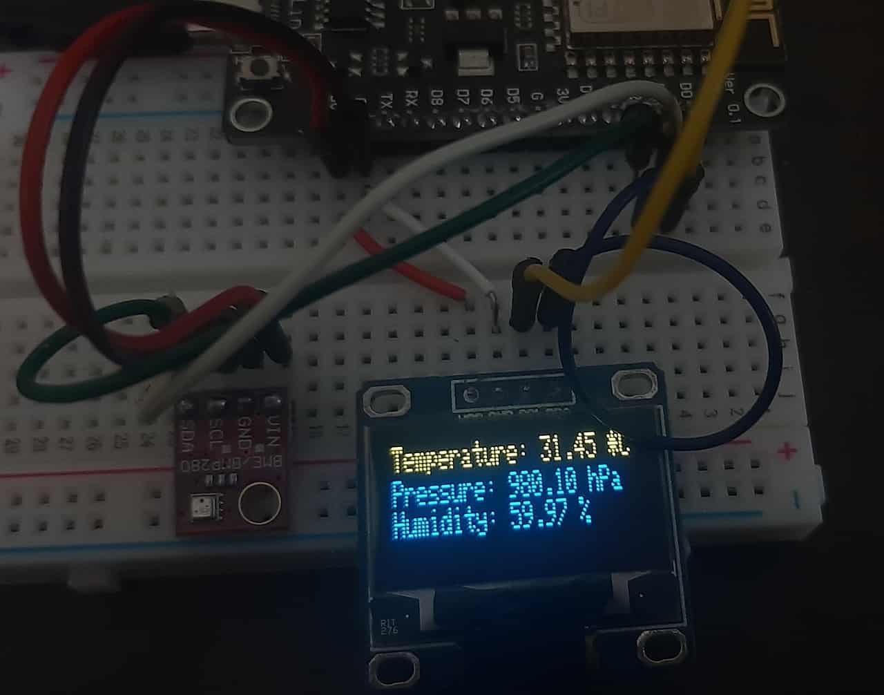
Once the code is uploaded to ESP8266 NodeMCU, open the serial monitor of Arduino IDE and set the baud rate to 115200. Finally, we can see the BME280 readings on Arduino serial monitor and on the OLED display as follows:
If you like this tutorial, you may also like to see other sensors interfacing with ESP8266 NodeMCU:
- MPU-6050 with ESP8266 NodeMCU Accelerometer, Gyroscope, and Temperature Sensor (Arduino IDE)
- BME680 with ESP8266 NodeMCU using Arduino IDE
- ESP8266 NodeMCU Send Sensor Readings to ThingSpeak using Arduino IDE (BME280)
- ESP32/ESP8266: Publish Sensor Readings to Google Sheets via IFTTT
- ESP8266 Send Sensor Readings to Google Firebase
Hello microcontrollers-team,
what can I do if I have an OLED display with a SH1106 chip ?
Thanks very much
Jürgen