In this tutorial, we will learn how to control ESP32 and ESP8266 NodeMCU outputs simultaneously from a web page and a physical push button by hosting a web server on them. In other words, if a user controls the LED with a push button, the state of the LED will be automatically updated on the web page. Similarly, the user can also control the output from a web page button.
The ESP32/ESP8266 will store the web pages in its code, and whenever a user requests a web page using an IP address, the web server will serve the stored pages to the user.
Previously, we built a momentary switch web server through which we could control the ESP32’s onboard LED. The web server featured a toggle button that acted as a momentary switch. This time, we will take that project a step further. In this user guide, we will control the ESP’s output through a web server as well as through a physical push button.
The web server will consist of a sliding button that will act as a toggle switch and control the output of the ESP board. Similarly, the same output will be controlled via a push button. The output state will be updated whenever either of the controllers (web server or push button) is used. In our program code, we will configure the ESP GPIO14 pin as an output, which will be connected to an LED. You can use any other output device as well, such as buzzers, relays, or different LEDs.
Recommended Components
The following components are used in this project or are helpful for building it with the ESP32.
| Component | How it’s used in this project | Buy on Amazon |
|---|---|---|
| ESP32 Development Board | Hosts the asynchronous web server and drives the LED output GPIO. | Check Price |
| ESP8266 NodeMCU | Alternative board this sketch also supports for the same web server. | Check Price |
| Micro USB Cable | Powers the board and uploads the sketch from your computer. | Check Price |
| Breadboard | Holds the LED, push button and resistors for prototyping. | Check Price |
| Jumper Wires | Wire the LED, push button and resistors to the GPIO pins. | Check Price |
| 5mm LED | The output controlled by both the web server and the push button. | Check Price |
| Resistor Kit (220 ohm / 4.7k) | Provides the 220Ω LED resistor and 10kΩ pull-down for the button. | Check Price |
| Tactile push button | Physical button that toggles the output alongside the web server. | Check Price |
As an Amazon Associate we earn from qualifying purchases. Prices and availability are accurate as of the date/time indicated and are subject to change.
Prerequisites
We will use Arduino IDE to program our ESP32/ESP8266 development board. Thus, you should have the latest version of Arduino IDE. Additionally, you also need to install the ESP32 and the ESP8266 plugin. If your IDE does not have the plugins installed you can visit the link below:
Installing ESP32 library in Arduino IDE and upload code
Installing ESP8266 library in Arduino IDE
Project Overview
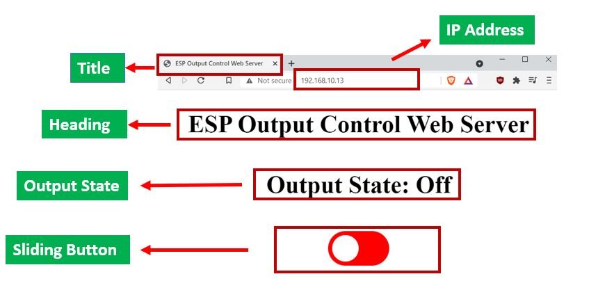
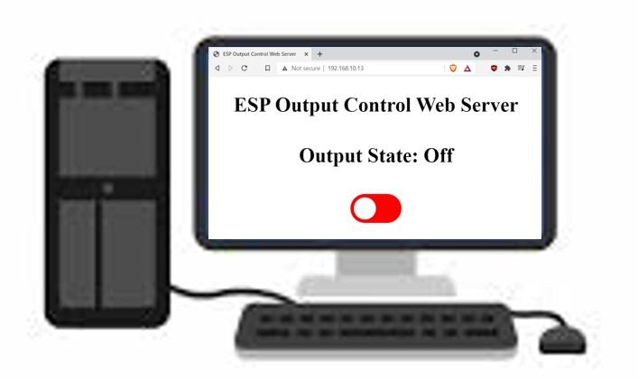
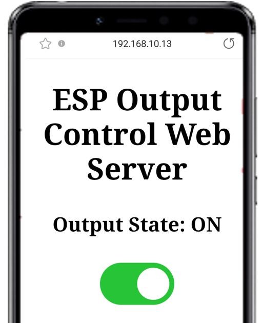
We will create an ESP web server based on a sliding switch. It will consist of a title, “ESP Output Control Web Server,” and a sliding button that will act as the switch. The output state (ON/OFF) will also be mentioned. The ESP board’s output (LED) will be connected with the push button. Our goal is to change the output state of the LED through both the web server and the physical push button. Additionally, the output state displayed on the web server should also update simultaneously if the sliding button is slid or the push button is pressed.
Connecting Hardware (ESP32/ESP8266 with LED and Push Button)
Required Components:
- ESP32/ ESP8266 module
- One LED
- 220-ohm resistor
- 10k ohm resistor
- Breadboard
- Connecting wires
For ESP8266
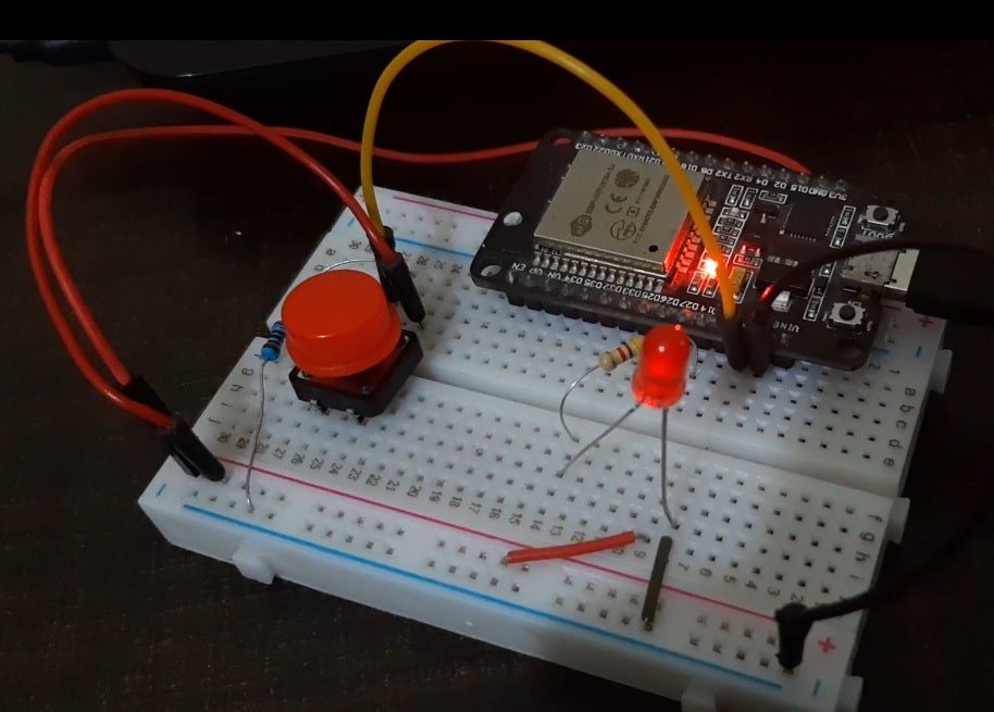
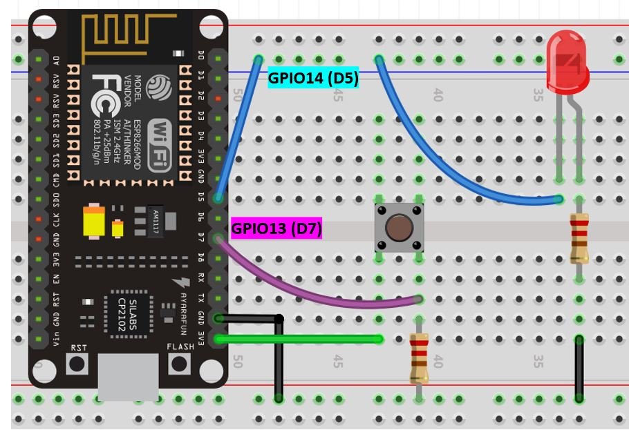
The below picture shows the schematic for ESP 8266 module with a push-button and LED. Assemble your circuit as follows:
For ESP32
Assemble your circuit as follows:
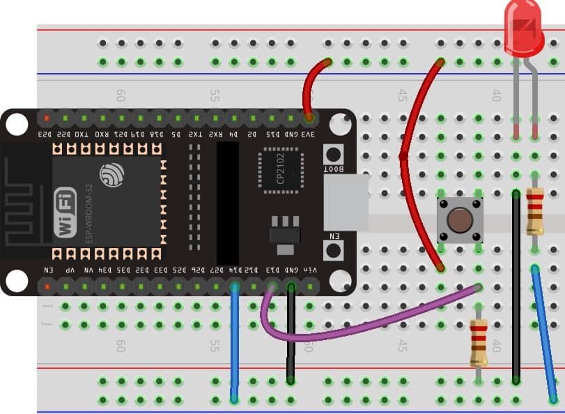
In the above schematics, we can see that GPIO 14 is connected with the anode pin of LED and the cathode pin is connected with the common ground through the 220-ohm resistor.
The push-button has four terminals. One terminal is powered by 3.3 volts from ESP8266 and the other terminal is connected by GPIO 13 and the 10k ohm resistor which acts as a pull-down resistor. The other end of the resistor is connected with the common ground.
When the push button is pressed, a logic state of high (1) will be passed on GPIO13 and the push button input will be in a high state. When the button is released a logic state of low (0) will be passed on GPIO13 and the push button input will be in a logic state LOW. We will read these two states of the push button and turn on and turn off the LED accordingly.
Recommended reading: Push button with ESP32 – GPIO pins as digital input
Installing ESPAsyncWebServer Library and Async TCP/ ESP Async TCP Library
We will build the asynchronous web server with the help of the ESPAsycWebServer library.
We will need two libraries to build our web server.
- ESP32: ESPAsyncWebServer & AsyncTCP
- ESP8266: ESPAsyncwebServer & ESPAsyncTCP
The ESPAsyncWebServer library will help us in creating our web server easily. With this library, we will set up an asynchronous HTTP server. AsyncTCP (for ESP32 only) and ESPAsyncTCP (for ESP8266 only) library will also be incorporated as it a dependency for the ESPAsyncWebServer library. All of these libraries are not available in the Arduino library manager. Therefore, we will have to download and load them on our ESP32/ESP8266 board ourselves.
For ESP32 & ESP8266:
- To install the ESPAsyncWebServer library for free, click here to download. You will download the library as a .zip folder which you will extract and rename as ‘ESPAsyncWebServer.’ Then, transfer this folder to the installation library folder in your Arduino IDE.
For ESP32 Only:
- To install the Async TCP library for free, click here to download. You will download the library as a .zip folder which you will extract and rename as ‘AsyncTCP.’ Then, transfer this folder to the installation library folder in your Arduino IDE.
For ESP8266 Only:
- To install the ESPAsync TCP library for free, click here to download. You will download the library as a .zip folder which you will extract and rename as ‘ESPAsyncTCP.’ Then, transfer this folder to the installation library folder in your Arduino IDE.
Likewise, you can also go to Sketch > Include Library > Add .zip Library inside the IDE to add the libraries as well. After installation of the libraries, restart your IDE.
Arduino Sketch
Open your Arduino IDE and go to File > New to open a new file. Copy the code given below in that file. This code will work for both ESP32 and ESP8266 development boards. You just need to enter your network credentials.
#ifdef ESP32
  #include <WiFi.h>
  #include <AsyncTCP.h>
#else
  #include <ESP8266WiFi.h>
  #include <ESPAsyncTCP.h>
#endif
#include <ESPAsyncWebServer.h>


const char* ssid = "Your_SSID"; //Write your SSID
const char* password = "Your_Password";   //Write your password

const char* input_parameter = "state";

const int output = 14;
const int Push_button_GPIO = 13 ;

// Variables will change:
int LED_state = LOW;
int button_state;
int lastbutton_state = LOW;

unsigned long lastDebounceTime = 0;
unsigned long debounceDelay = 50;

AsyncWebServer server(80);

const char index_html[] PROGMEM = R"rawliteral(
<!DOCTYPE HTML><html>
<head>
  <title>ESP Output Control Web Server</title>
  <meta name="viewport" content="width=device-width, initial-scale=1">
  <style>
    html {font-family: Times New Roman; display: inline-block; text-align: center;}
    h2 {font-size: 3.0rem;}
    h4 {font-size: 2.0rem;}
    p {font-size: 3.0rem;}
    body {max-width: 900px; margin:0px auto; padding-bottom: 25px;}
    .switch {position: relative; display: inline-block; width: 120px; height: 68px}
    .switch input {display: none}
    .slider {position: absolute; top: 0; left: 0; right: 0; bottom: 0; background-color: #FF0000; border-radius: 34px}
    .slider:before {position: absolute; content: ""; height: 52px; width: 52px; left: 8px; bottom: 8px; background-color: #fff; -webkit-transition: .4s; transition: .4s; border-radius: 68px}
    input:checked+.slider {background-color: #27c437}
    input:checked+.slider:before {-webkit-transform: translateX(52px); -ms-transform: translateX(52px); transform: translateX(52px)}
  </style>
</head>
<body>
  <h2>ESP Output Control Web Server</h2>
  %BUTTONPLACEHOLDER%
<script>function toggleCheckbox(element) {
  var xhr = new XMLHttpRequest();
  if(element.checked){ xhr.open("GET", "/update?state=1", true); }
  else { xhr.open("GET", "/update?state=0", true); }
  xhr.send();
}

setInterval(function ( ) {
  var xhttp = new XMLHttpRequest();
  xhttp.onreadystatechange = function() {
    if (this.readyState == 4 && this.status == 200) {
      var inputChecked;
      var outputStateM;
      if( this.responseText == 1){
        inputChecked = true;
        outputStateM = "ON";
      }
      else {
        inputChecked = false;
        outputStateM = "OFF";
      }
      document.getElementById("output").checked = inputChecked;
      document.getElementById("outputState").innerHTML = outputStateM;
    }
  };
  xhttp.open("GET", "/state", true);
  xhttp.send();
}, 1000 ) ;
</script>
</body>
</html>
)rawliteral";

String processor(const String& var){
  if(var == "BUTTONPLACEHOLDER"){
    String buttons ="";
    String outputStateValue = outputState();
    buttons+= "<h4>Output State: <span id=\"outputState\"></span></h4><label class=\"switch\"><input type=\"checkbox\" onchange=\"toggleCheckbox(this)\" id=\"output\" " + outputStateValue + "><span class=\"slider\"></span></label>";
    return buttons;
  }
  return String();
}

String outputState(){
  if(digitalRead(output)){
    return "checked";
  }
  else {
    return "";
  }
  return "";
}

void setup(){
  // Serial port for debugging purposes
  Serial.begin(115200);

  pinMode(output, OUTPUT);
  digitalWrite(output, LOW);
  pinMode(Push_button_GPIO, INPUT);

  // Connect to Wi-Fi
  WiFi.begin(ssid, password);
  while (WiFi.status() != WL_CONNECTED) {
    delay(1000);
    Serial.println("Connecting to WiFi..");
  }


  Serial.println("IP Address: ");
  Serial.println(WiFi.localIP());


  server.on("/", HTTP_GET, [](AsyncWebServerRequest *request){
    request->send_P(200, "text/html", index_html, processor);
  });


  server.on("/update", HTTP_GET, [] (AsyncWebServerRequest *request) {
    String input_message;
    String inputParameter;
    // GET input1 value on <ESP_IP>/update?state=<input_message>
    if (request->hasParam(input_parameter)) {
      input_message = request->getParam(input_parameter)->value();
      inputParameter = input_parameter;
      digitalWrite(output, input_message.toInt());
      LED_state = !LED_state;
    }
    else {
      input_message = "No message sent";
      inputParameter = "none";
    }
    Serial.println(input_message);
    request->send(200, "text/plain", "OK");
  });


  server.on("/state", HTTP_GET, [] (AsyncWebServerRequest *request) {
    request->send(200, "text/plain", String(digitalRead(output)).c_str());
  });
  // Start server
  server.begin();
}

void loop() {
  int data = digitalRead(Push_button_GPIO);

  if (data != lastbutton_state) {
    // reset the debouncing timer
    lastDebounceTime = millis();
  }

  if ((millis() - lastDebounceTime) > debounceDelay) {
    if (data != button_state) {
      button_state = data;


      if (button_state == HIGH) {
        LED_state = !LED_state;
      }
    }
  }


  digitalWrite(output, LED_state);


  lastbutton_state = data;
}
How does the Code Work?
Including Libraries
Firstly, we will include all the necessary libraries which are required for this project. As this code is compatible with both ESP32 and ESP8266 thus both libraries (WiFi.h and ESP8266WiFi.h) are defined. This library will help in establishing the connection between our ESP module to a wireless network. We will also import the two libraries which we installed previously, the ESPAsyncWebServer library and the ESPAsyncTCP library.
#ifdef ESP32
  #include <WiFi.h>
  #include <AsyncTCP.h>
#else
  #include <ESP8266WiFi.h>
  #include <ESPAsyncTCP.h>
#endif
#include <ESPAsyncWebServer.h>
Setting Network Credentials
Next, we will create two global variables, one for the SSID and the other for the password. These will hold our network credentials which will be used to connect to our wireless network. Replace both of them with your credentials to ensure a successful connection.
const char* ssid = "Your_SSID";
const char* password = "Your_Password";
Setting Input Parameters
We will pass another global variable of type char. This will be the input parameter which we will call ‘state.’
const char* input_parameter = "state";Setting LED and Push Button GPIOs
Then, we will define the variable ‘output’ to save the GPIO pin through which the LED is connected i.e., GPIO14. Another variable ‘Push_button_GPIO’ will specify the pin through which it is connected with the ESP board. You can use any suitable output/input GPIO pins. We have used GPIO14 and GPIO13.
const int output = 14;
const int Push_button_GPIO = 13;
Defining LED and Push Button States
Next, we will define the states of the LED and the push button. We have specified ‘LED_state’ as LOW. This means at the time of boot the LED will be OFF. The ‘button_state’ variable will save the current state of the push button whereas ‘lastbutton_state’ will hold the last previous state of the push button. We have also set the ‘lastbutton_state’ to LOW to make sure the LED stays OFF when we start.
int LED_state = LOW;
int button_state;
int lastbutton_state = LOW;
Creating the AsyncWebServer Object
The AsyncWebServer object will be used to set up the ESP web server. We will pass the default HTTP port which is 80, as the input to the constructor. This will be the port where the server will listen to the requests.
AsyncWebServer server(80);
Creating the Web Page
We will create an index_html variable to store all the HTML, CSS and Javascript text which will be required to build our web page. We will start with the title of the web page. The <title> tag will indicate the beginning of the title and the </tile> tag will indicate the ending. In between these tags, we will specify “ESP Output Control Web Server” which will be displayed in the browser’s title bar.
<title>ESP Output Control Web Server</title>Next, we will create a meta tag to make sure our web server is available for all browsers e.g., smartphones, laptops, computers etc.
<meta name="viewport" content="width=device-width, initial-scale=1">CSS styling
Inside the index_html variable we have the tags which mark the beginning and end of the CSS styling file.
We will set the display text to font type Times New Roman and align it in the centre of the webpage. For the headings and the sliding button, the font size, font type, colour, positioning and everything relating to the overall visuals of the web page will be is specified. We will distinguish the slider through colour.
Red colour slider: LED OFF.
Green colour slider: LED ON.
This section of code shows the CSS styling which we will incorporate in our web page.
<style>
    html {font-family: Times New Roman; display: inline-block; text-align: center;}
    h2 {font-size: 3.0rem;}
    h4 {font-size: 2.0rem;}
    p {font-size: 3.0rem;}
    body {max-width: 900px; margin:0px auto; padding-bottom: 25px;}
    .switch {position: relative; display: inline-block; width: 120px; height: 68px}
    .switch input {display: none}
    .slider {position: absolute; top: 0; left: 0; right: 0; bottom: 0; background-color: #FF0000; border-radius: 34px}
    .slider:before {position: absolute; content: ""; height: 52px; width: 52px; left: 8px; bottom: 8px; background-color: #fff; -webkit-transition: .4s; transition: .4s; border-radius: 68px}
    input:checked+.slider {background-color: #27c437}
    input:checked+.slider:before {-webkit-transform: translateX(52px); -ms-transform: translateX(52px); transform: translateX(52px)}
  </style>
HTML Body
The next step will be to define the HTML web page body. This will go inside the <body></body> tags which mark the beginning and the ending of the script. This part will include the heading of the web page and the button. We will include the heading of our webpage inside the <h2></h2> tags and it will be ‘ESP Output Control Web Server’. You can use any other heading as you prefer.
<h2>ESP Output Control Web Server</h2>We will use a placeholder to monitor the correct GPIO states. %BUTTONPLACEHOLDER% will be used as the placeholder which will help us in creating the button in the processor() function. It will get replaced by the HTML text to build the button on our web page. We are using a placeholder because we simultaneously want to change the sliding button (red/green) whenever the output state will be changed. This time that can be achieved through a physical push button as well.
%BUTTONPLACEHOLDER%toggleCheckbox() function
We will use JavaScript to create the toggleCheckbox() function which checks for the correct toggle feature of our sliding button through an if-else statement. It will create the HTTP GET request whenever a button will be slid over inside the if-else statement and turn the LED ON or OFF accordingly.
Firstly, we will create an XMLHttpRequest . Then, we will initialize the GET request by using the xhr.open() method. Inside it, we will pass on three arguments. The first argument specifies the type of HTTP method which is GET in our case. The second argument is the URL to which are ESP32/ESP8266 will request upon. In our case, it will be either /update?state=1 or /update?state=0 URL depending on the state of the button. The last argument is true which specifies that the request is asynchronous. Lastly, we will use xhr.send() to open the connection. Our server (ESP32/ESP8266) will now be able to receive the HTTP GET request whenever the user will interact with the sliding button.
function toggleCheckbox(element) {
  var xhr = new XMLHttpRequest();
  if(element.checked){ xhr.open("GET", "/update?state=1", true); }
  else { xhr.open("GET", "/update?state=0", true); }
  xhr.send();
}
Updating Output State
The following JavaScript function will make sure that the output state always stays updated and displays the current LED state. This is achieved by making a GET request on the /state URL after every second.
setInterval(function ( ) {
  var xhttp = new XMLHttpRequest();
  xhttp.onreadystatechange = function() {
    if (this.readyState == 4 && this.status == 200) {
      var inputChecked;
      var outputStateM;
      if( this.responseText == 1){
        inputChecked = true;
        outputStateM = "ON";
      }
      else {
        inputChecked = false;
        outputStateM = "OFF";
      }
      document.getElementById("output").checked = inputChecked;
      document.getElementById("outputState").innerHTML = outputStateM;
    }
  };
  xhttp.open("GET", "/state", true);
  xhttp.send();
}, 1000 ) ;
processor() function
Inside the processor() function, we will replace the placeholder (%BUTTONPLACEHOLDER%) and build the sliding button. This will occur whenever the web page will be accessed and if the placeholder is found inside the HTML script. The button variable will be of the type string and we will pass an empty string at first. Then we will call the outputState() function and save its value in the ‘outputStateValue.’
Finally, we will concatenate the HTML text for the button according to the current output state (outputStateValue) and build the button accordingly displaying both the sliding button and the output state of the GPIO on top of it.
String processor(const String& var){
  if(var == "BUTTONPLACEHOLDER"){
    String buttons ="";
    String outputStateValue = outputState();
    buttons+= "<h4>Output State: <span id=\"outputState\"></span></h4><label class=\"switch\"><input type=\"checkbox\" onchange=\"toggleCheckbox(this)\" id=\"output\" " + outputStateValue + "><span class=\"slider\"></span></label>";
    return buttons;
  }
  return String();
}
outputState() function
The outputState() function will return the current state of the ‘output’ by using digitalRead() on the output argument. The ‘output’ in this case was GPIO14 through which the LED was connected.
String outputState(){
  if(digitalRead(output)){
    return "checked";
  }
  else {
    return "";
  }
  return "";
}
setup() function
Inside the setup() function, we will open a serial connection at a baud rate of 115200. By using the pinMode() function, the GPIO Pin will be passed as a parameter inside the function which will be configured as an output pin. We will initialize this pin to a LOW state at the time of boot that means the LED will be OFF. Additionally, we will specify the push button as an input as well.
Serial.begin(115200);
pinMode(output, OUTPUT);
digitalWrite(output, LOW);
pinMode(Push_button_GPIO, INPUT);
The following section of code will connect our ESP board with the local network whose network credentials we already specified above. After the connection will be established, the IP address of the ESP board will get printed on the serial monitor. This will help us to make a request to the server.
WiFi.begin(ssid, password);
  while (WiFi.status() != WL_CONNECTED) {
    delay(1000);
    Serial.println("Connecting to WiFi..");
  }
  Serial.println("IP Address: ");
  Serial.println(WiFi.localIP());
ESP32/ESP8266 Handling Requests
In this section, we will discuss how our ESP board will handle the requests on the different URLs.
/root URL
Firstly, we will deal with the /root URL request which the ESP board will receive.
We will use the send_P() method. This method will take in four parameters. The first is 200 which is the HTTP status code for ‘ok’. The second is “text/html” which will correspond to the content type of the response. The third input is the text saved on the index_html variable which will be sent. As we are creating the sliding button in the processor() function thus both the HTML page as well as the processor() function will be sent.
  server.on("/", HTTP_GET, [](AsyncWebServerRequest *request){
    request->send_P(200, "text/html", index_html, processor);
  });
/update URL
The following section of code will check whether the LED is ON or OFF by accessing the request received on the particular URL. If the URL corresponds to /update?state=1 then the LED state is HIGH otherwise if the URL is /update?state=0 then the LED state is LOW. It will change the value saved in the ‘LED_state,’ according to the URL.
server.on("/update", HTTP_GET, [] (AsyncWebServerRequest *request) {
    String input_message;
    String inputParameter;
    if (request->hasParam(input_parameter)) {
      input_message = request->getParam(input_parameter)->value();
      inputParameter = input_parameter;
      digitalWrite(output, input_message.toInt());
      LED_state = !LED_state;
    }
    else {
      input_message = "No message sent";
      inputParameter = "none";
    }
    Serial.println(input_message);
    request->send(200, "text/plain", "OK");
  });
Whenever the ESP receives a request on the /state URL, the current output state will be sent as a response.
server.on("/state", HTTP_GET, [] (AsyncWebServerRequest *request) {
    request->send(200, "text/plain", String(digitalRead(output)).c_str());
  });
To start the server, we will call the begin() on our server object.
server.begin();loop() function
In the loop() function we will check whether the physical push button was pressed or not and toggle the LED accordingly.
int data = digitalRead(Push_button_GPIO);
  if (data != lastbutton_state) {
    lastDebounceTime = millis();
  }

  if ((millis() - lastDebounceTime) > debounceDelay) {
    if (data != button_state) {
      button_state = data;
      if (button_state == HIGH) {
        LED_state = !LED_state;
      }
    }
  }

  digitalWrite(output, LED_state);
  lastbutton_state = data;
Demonstration
After you have uploaded your code to the ESP32/ESP8266 development board press its ENABLE/RST button.


In your Arduino IDE, open up the serial monitor and you will be able to see the IP address of your ESP module.
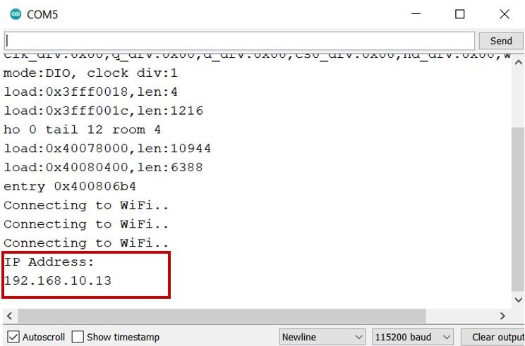
Copy that address into a web browser and press enter. The web server will look something like this:
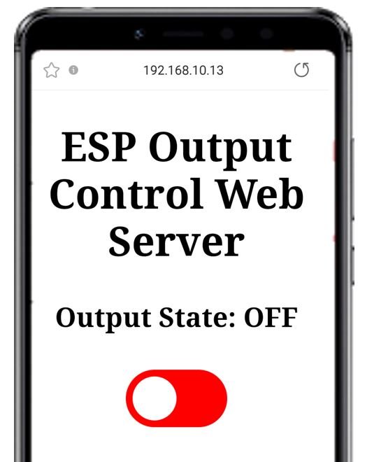
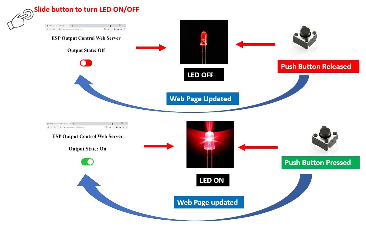
Now you can slide the button and toggle the output connected to the LED. Moreover, you can press the push button to toggle the same LED as well. The web page will automatically update to a new GPIO state whenever the physical push button will be pressed or the sliding button will be slid over.
Video Demo
Conclusion
In this guide, we learnt how to control the ESP32/ESP8266’s output simultaneously through a web server and a physical push button. In this project, we used a simple LED as an output. Likewise, you can control any other output or incorporate multiple ESP outputs as well by increasing the sliding buttons.
If you found this ESP32 and ESP8266 web server project useful, you can also read related projects:
- ESP8266 Send Sensor Readings to Google Firebase and Build an Android app to display Data
- ESP32 Send Sensor Readings to Google Firebase and Build an Android app to display Data
- ESP8266 NodeMCU Server-Sent Events (SSE) Web Server (Arduino IDE)
- ESP32 Server-Sent Events (SSE) Web Server (Arduino IDE)
- ESP32/ESP8266 Momentary Switch Web Server: Control GPIO Outputs
- Displaying Images in ESP32 and ESP8266 Web Server
- ESP32/ESP8266 Web Server to Control Outputs with a Timer (Pulse Width)
Hello. Great instructional piece. Thanks…
I am working to increase the number of switch on the web page and ESP8266. Is the a designed way to do this? I created another web sw by duplicating the buttons+= line and changing the name it has but I cannot find a way to logically separate them and test for the status of each switch. Do you have any docs you could point me to?
Thanks in advance
Stephen…
Hi
You only need to change the GPIO pins number after replicating the buttons+ lines.
This project will be good for my workshop but with 4 relays IE light, Iron, bench power, heater.
Looking at the comments above I see the question has been asked and the reply was just to use more GPIO pins, so I think I will try to make it and thanks again for sharing your hard work not everyone finds it easy to code.
Bob
How can you add like as many buttons as you want
I want to add 3 buttons if it can help, thank you
I want to add more buttons if it can help, thank you