In this tutorial, we will learn how to build an android app that will control the outputs of ESP32 over WiFi and internet using an Android App. We will control the output GPIO pins of the ESP32 module by toggling the two LEDs connected with the GPIO pins of the module. This android app will be created with MIT App Inventor.
Recommended Components
The following components are used in this project or are helpful for building it with the ESP32.
| Component | How it’s used in this project | Buy on Amazon |
|---|---|---|
| ESP32 Development Board (DevKit V1) | Hosts the web server and toggles the GPIO pins controlled from the Android app. | Check Price |
| Micro USB Cable | Connects the ESP32 to your computer for uploading the sketch and powering the board. | Check Price |
| Breadboard | Holds the two LEDs and resistors while wiring them to the ESP32 GPIO pins. | Check Price |
| Jumper Wires | Make the connections between the ESP32, LEDs, and resistors on the breadboard. | Check Price |
| 5mm LED | The two output LEDs at GPIO4 and GPIO5 that the Android app turns ON and OFF. | Check Price |
| Resistor Kit (220 Ω / 4.7k) | Provides the 220Ω current-limiting resistors in series with each LED. | Check Price |
As an Amazon Associate we earn from qualifying purchases. Prices and availability are accurate as of the date/time indicated and are subject to change.
ESP32 Outputs Controller Android App Project Overview

We will create an Arduino IoT app through ESP32 and MIT App Inventor to control the outputs of ESP32.
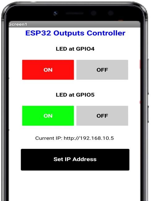
Firstly, the ESP32 module will connect to the local network. The IP address will be displayed in the serial monitor of Arduino IDE. Inside the android app, the user will first set the IP address to that of the ESP32 module. Click the ‘Set IP Address’ button. A text box and save button will appear. Enter the IP address that you got in the serial monitor and click the Save button. The android app will save the IP address of the ESP32 module.
Next, to control the two LEDs click the respective ON and OFF buttons and the LEDs connected with the respective GPIO pins will turn ON and OFF. The state of the GPIO pin will also be displayed.
A steady internet connection is a must.
We will require the following for our project:
Hardware Required:
- ESP32 development board
- Two LEDs
- Two 220 ohm current limiting resistors
- Connecting Wires
- Breadboard
Software Required:
- Arduino IDE
- MIT App Inventor
- Android Smartphone with MIT AI2 Companion installed
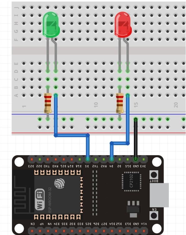
ESP32 Outputs Control Hardware Setup
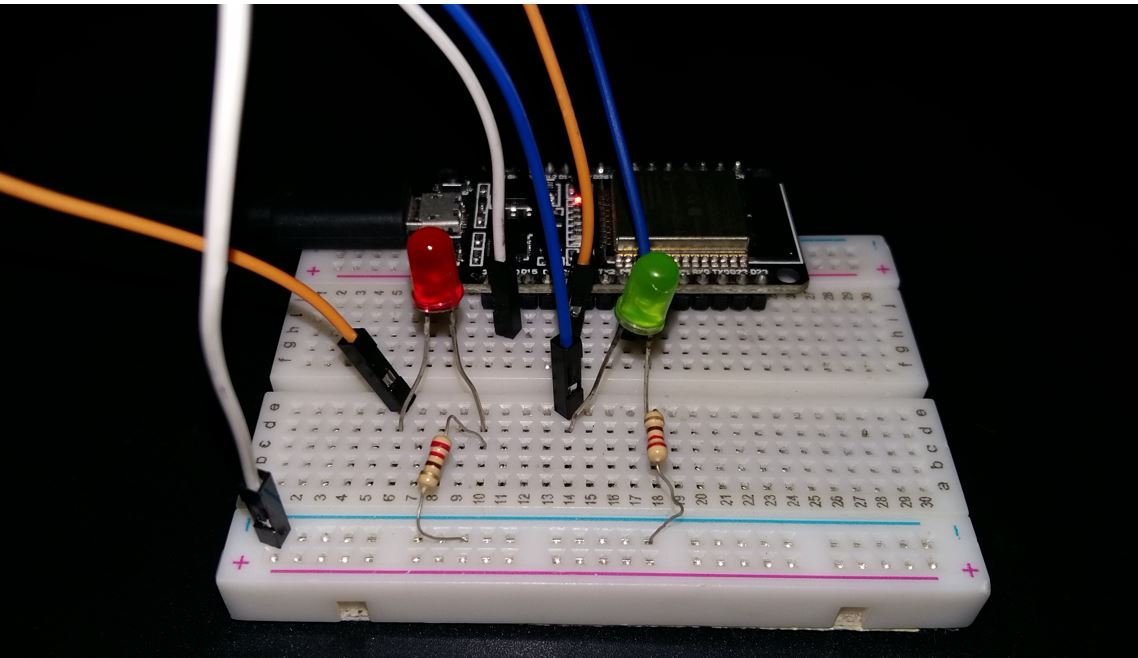
In the below schematic, we can see that GPIO4 is connected with the anode pin of the red LED, and the cathode pin is connected with the common ground through the 220-ohm resistor. Likewise, GPIO5 is connected with the anode pin of the green LED, and the cathode pin is connected with the common ground through the 220-ohm resistor. These two GPIO pins will be configured as output pins in the program sketch.
Setting up Arduino IDE
To follow this project, make sure you have the latest version of Arduino IDE and the ESP32 add-on installed on your Arduino IDE. If you have not installed it before you can follow this tutorial:
Install ESP32 in Arduino IDE ( Windows, Linux, and Mac OS)
Arduino Sketch ESP32 Control Outputs with Android App
Open your Arduino IDE and go to File > New to open a new file. Copy the code given below in that file.
In the following sketch, the ESP32 hosts a web server that allows the user to control GPIO4 and GPIO5 through buttons. These GPIO pins are connected with LEDs and configured as output pins. The web server consists of ON and OFF buttons for each LED. Clicking the button, generates a HTTP request on a URL and the ESP32 responds accordingly by setting the specified output pin HIGH or LOW.
Make sure to replace the network credentials to successfully connect with your local Wi-Fi.
#include <WiFi.h>
#include <WiFiClient.h>
#include <WebServer.h>
#include <ESPmDNS.h>
MDNSResponder mdns;
const char* ssid = "REPLACE_WITH_YOUR_SSID";
const char* password = "REPLACE_WITH_YOUR_PASSWORD";
WebServer server(80);
String webpage = "";
int led1 = 4;
int led2 = 5;
void setup(void) {
webpage += "<h1>ESP32 Web Server</h1><p>LED at GPIO4 <a href=\"led1ON\"><button>ON</button></a> <a href=\"led1OFF\"><button>OFF</button></a></p>";
webpage += "<p>LED at GPIO5 <a href=\"led2ON\"><button>ON</button></a> <a href=\"led2OFF\"><button>OFF</button></a></p>";
pinMode(led1, OUTPUT);
digitalWrite(led1, LOW);
pinMode(led2, OUTPUT);
digitalWrite(led2, LOW);
delay(1000);
Serial.begin(115200);
WiFi.begin(ssid, password);
Serial.println("");
while (WiFi.status() != WL_CONNECTED) {
delay(500);
Serial.print(".");
}
Serial.println("");
Serial.print("Connected to ");
Serial.println(ssid);
Serial.print("IP address: ");
Serial.println(WiFi.localIP());
if (mdns.begin("esp")) {
Serial.println("MDNS responder started");
}
server.on("/", []() {
server.send(200, "text/html", webpage);
});
server.on("/led1ON", []() {
server.send(200, "text/html", webpage);
digitalWrite(led1, HIGH);
delay(1000);
});
server.on("/led1OFF", []() {
server.send(200, "text/html", webpage);
digitalWrite(led1, LOW);
delay(1000);
});
server.on("/led2ON", []() {
server.send(200, "text/html", webpage);
digitalWrite(led2, HIGH);
delay(1000);
});
server.on("/led2OFF", []() {
server.send(200, "text/html", webpage);
digitalWrite(led2, LOW);
delay(1000);
});
server.begin();
Serial.println("HTTP server started");
}
void loop(void) {
server.handleClient();
}When the user will click the ON/OFF buttons, the web page will redirect to either /led1ON or /led1OFF URL for led1 and /led2ON and /led2OFF URL for led2. Whenever an HTTP GET request is made on the specified URL, the LED connected with the respective GPIO of the ESP32 module will turn ON or OFF accordingly.
Building App with MIT APP Inventor
MIT App Inventor is an incredible web application that helps users build interesting Android applications. It is a block-based programming tool through which users can create fully functional apps for Android devices such as smartphones, tablets e.tc. Often termed beginner-friendly, even people with no prior experience in programming can easily learn how to use this application efficiently. We will use this tool to build our Arduino app as well.
Steps to Create Android App
Go to the following website: and click the ‘Create Apps!’ button.

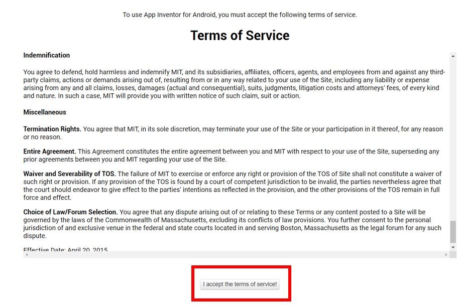
You will be redirected to a new window where you will be asked to sign in with your email account. After signing in you will have to accept the terms as shown below.
You will receive a welcome message. You can visit the link to get more information on how to install the inventor on your smartphone. Press ‘Continue’ to proceed. If you want, you can have a look at the tutorials being specified. Otherwise, go to ‘Start a blank project’ to start your app invention.

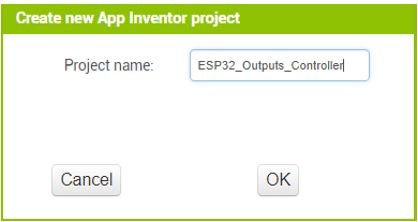
You will be asked to specify your project name. Choose an appropriate name. Click ‘ok.’
The Designer opens up. This is where we will design the user interface of our app. We can add text, buttons, images and various other functionalities to our app by dragging and dropping components from the palette to the viewer. Then we will set their attributes through the ‘Properties’ column.
Create Design
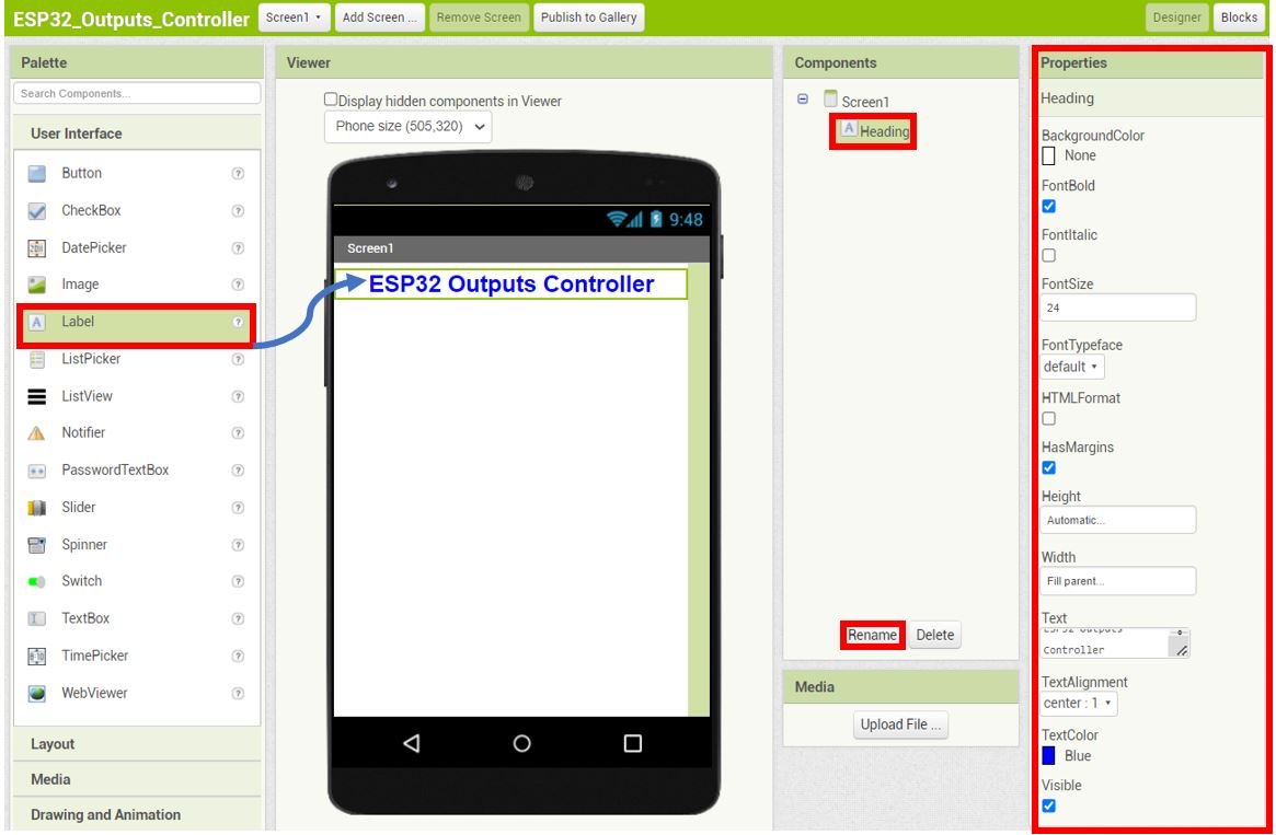
Firstly, we will add a heading for our app. Go to Palette > User Interface and head over to ‘Label.’ Now click and drag the label. Drop it on the Viewer side. Now you will be able to view it in the viewer as well as in the components list. Rename it as ‘Heading‘ as shown in the Components section.
Head over to the ‘Properties’ to change the text, font size and colour. The label will automatically update in the viewer. Keep in mind the viewer will show you the final look of your app which will appear on your smartphone.
You can change the properties of the label to incorporate your preferred spacing dimension by changing the width and height of the label.
LED 1 Controller Section
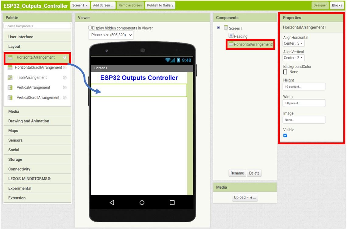
Next select HorizontalArrangement from the Layout. Set the Properties as shown below.
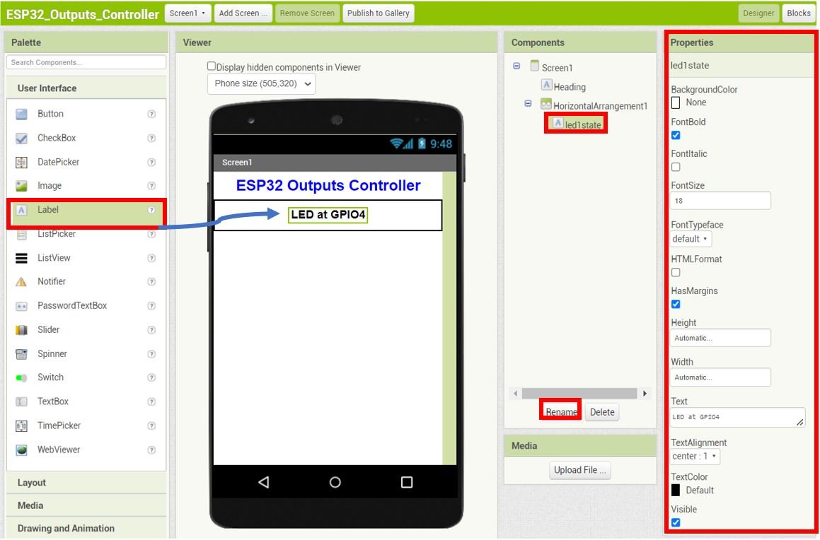
Go to Palette > User Interface and head over to ‘Label.’ Now click and drag the label. Drop it on the Viewer side. Rename it as ‘led1state‘ as shown in the Components section.
Head over to the ‘Properties’ to change the text, font size and colour.
Add another HorizontalArrangement beneath the led1state label. Set the Properties as shown below.
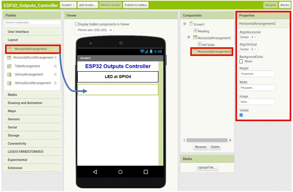
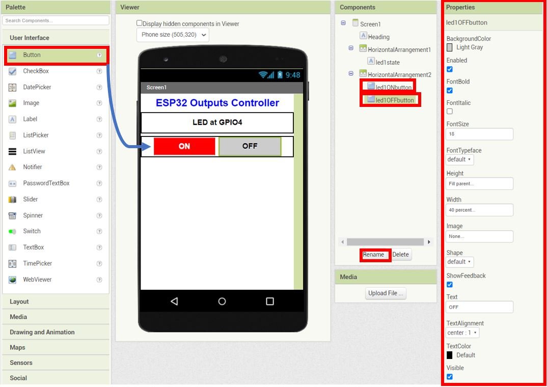
Go to User Interface > Button and drag and drop two buttons in the HorizontalArrangement2. Rename the buttons as ‘led1ONbutton‘ and ‘led1OFFbutton‘ respectively. Moreover, change the properties of the buttons as well accordingly. These buttons will be used to control the LED at GPIO4.
The picture below shows the Properties of the led1OFFbutton.
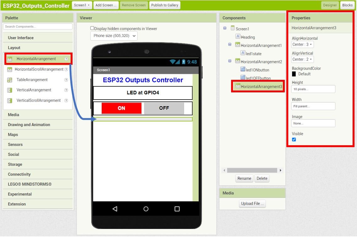
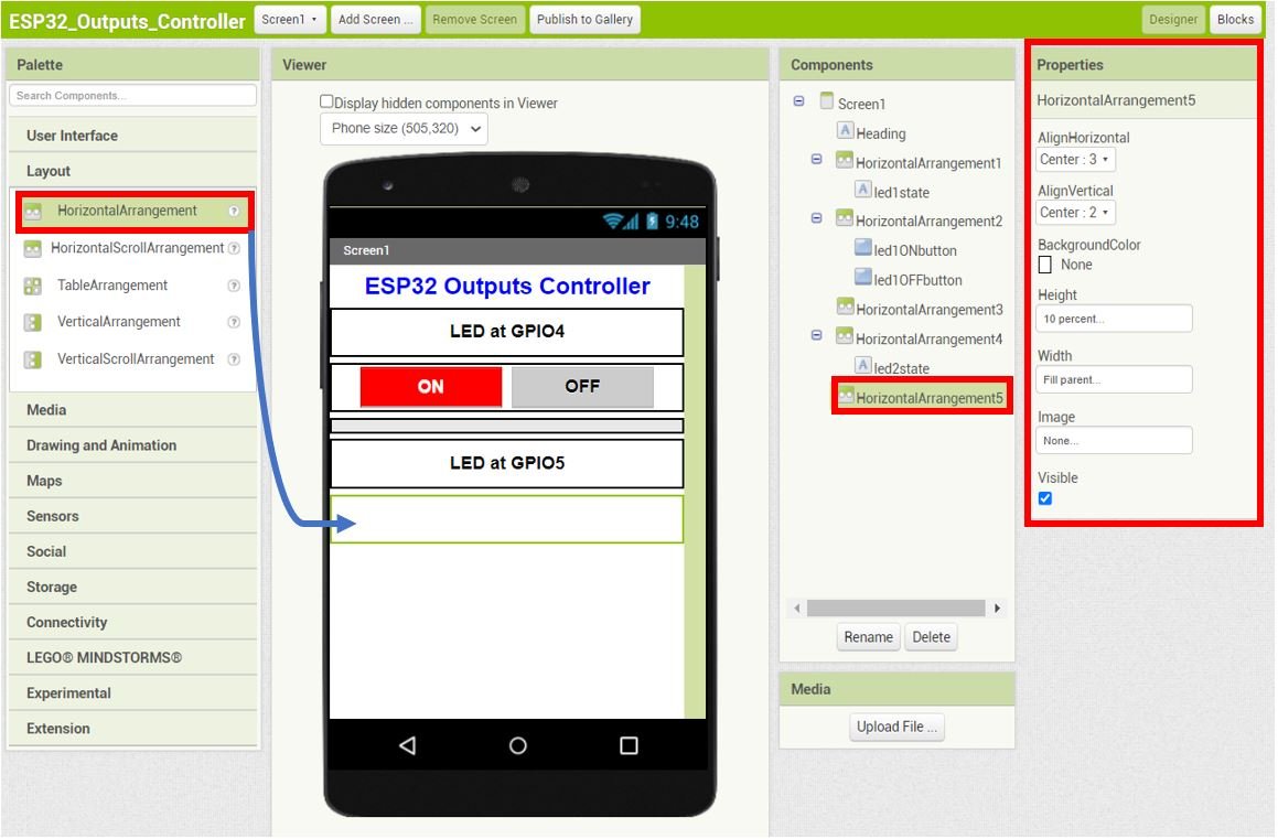
To add spacing between the first LED section and the second LED section, we will add a HorizontalArrangement of height 10 pixels beneath HorizontalArrangement2.
LED 2 Controller Section
Similarly, we will create the section for the second LED.
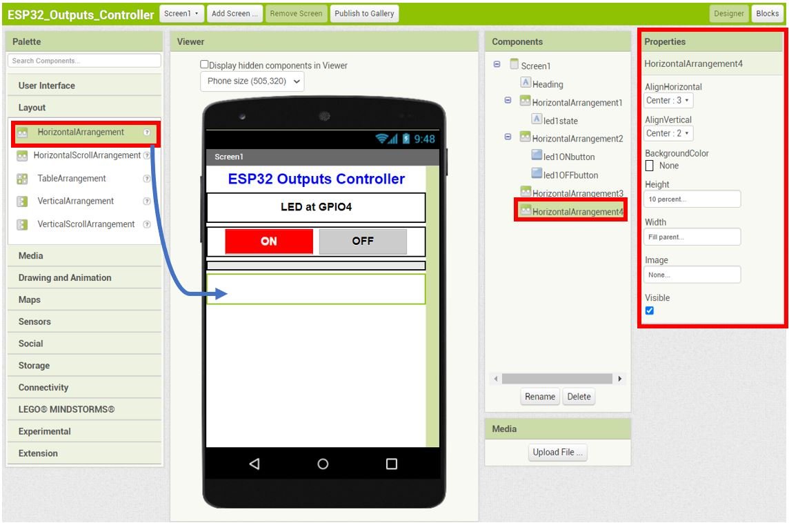
Next select HorizontalArrangement from the Layout and place it beneath HorizontalArrangement3. Set the Properties as shown below.
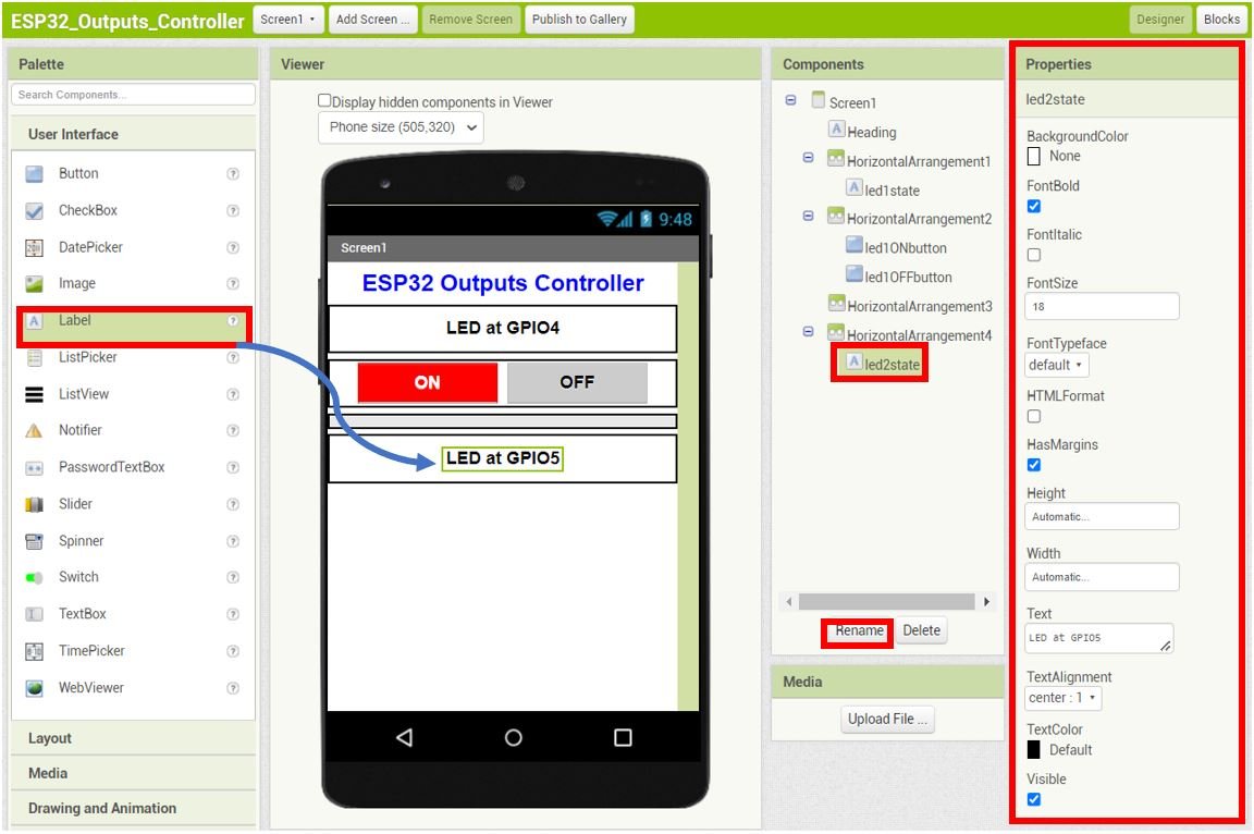
Go to Palette > User Interface and head over to ‘Label.’ Now click and drag the label. Drop it on the Viewer side. Rename it as ‘led2state‘ as shown in the Components section.
Head over to the ‘Properties’ to change the text, font size and colour.
Add another HorizontalArrangement beneath the led2state label. Set the Properties as shown below.
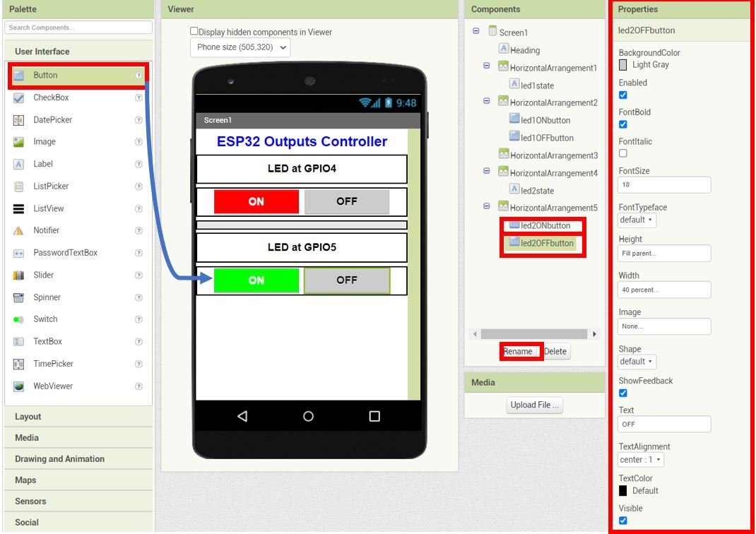
Go to User Interface > Button and drag and drop two buttons in the HorizontalArrangement5. Rename the buttons as ‘led2ONbutton‘ and ‘led2OFFbutton‘ respectively. Moreover, change the properties of the buttons as well accordingly. These buttons will be used to control the LED at GPIO5.
The picture below shows the Properties of the led2OFFbutton.
Current IP Address Information
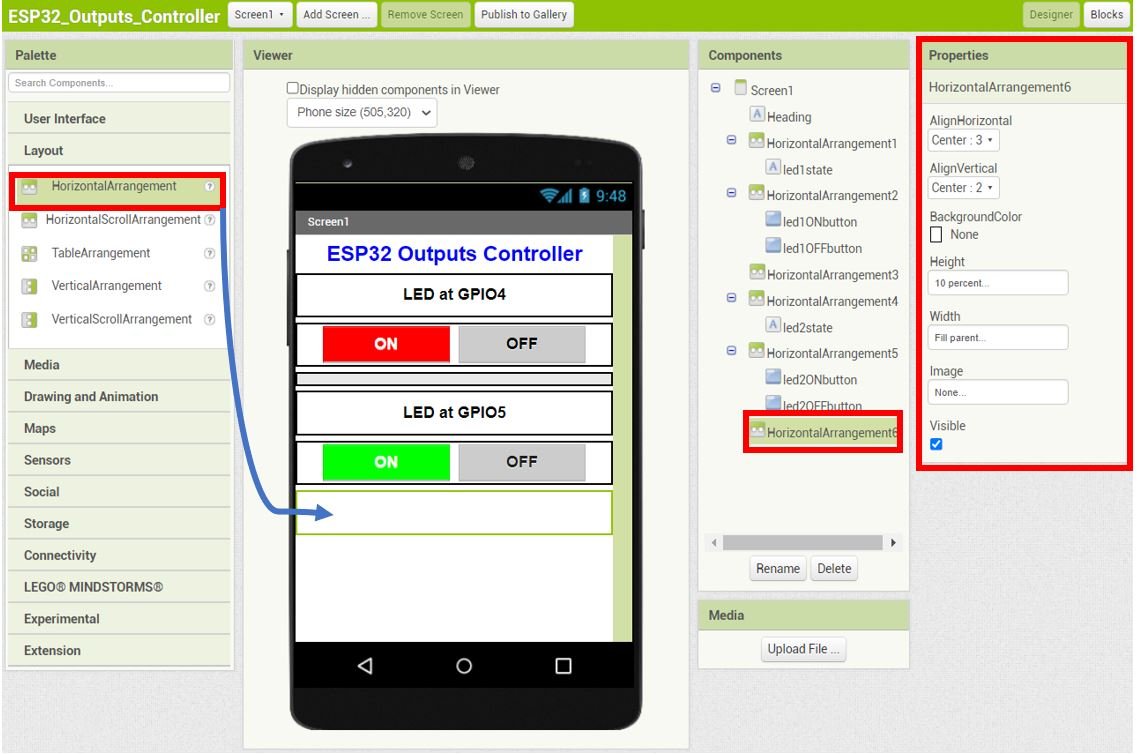
Next add a HorizontalArrangement beneath HorizontalArrangement5. Set its Properties as shown below:
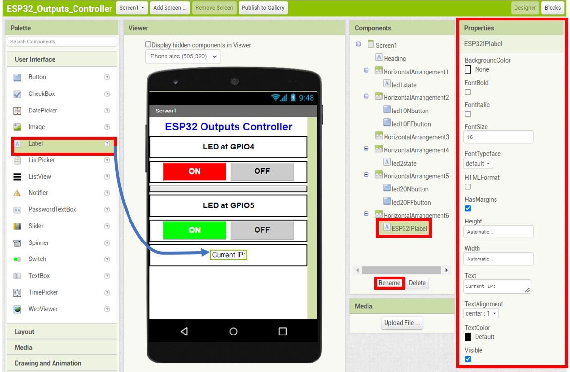
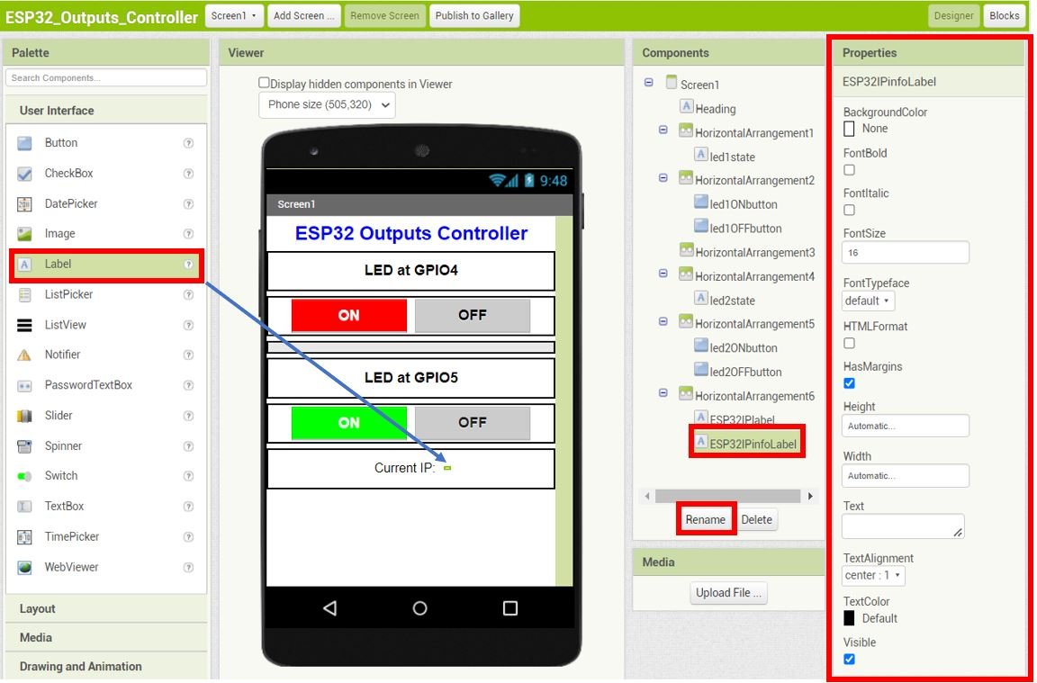
Go to Palette > User Interface and head over to ‘Label.’ Now click and drag the label. Drop it inside HorizontalArrangement6. Rename it as ‘ESP32IPlabel‘ as shown in the Components section. The text is set to Current IP: in this.
Head over to the ‘Properties’ to change the text, font size and colour.
Now drag another label and drop it beside ESP32IPlabel as shown below. Rename it as ‘ESP32IPinfoLabel.’ The text is empty in this.
Save IP Address
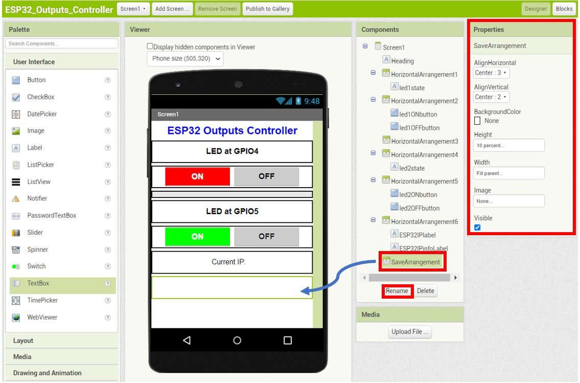
Add another HorizontalArrangement beneath HorizontalArrangement6. Rename it as ‘SaveArrangement‘ as shown in the Components section. This arrangement will only be visible when the user will click the ‘Set IP Address’ button.
Set its Properties as shown below. Initially turn the visibility of on because we have to place a textbox and a button inside this arrangement.
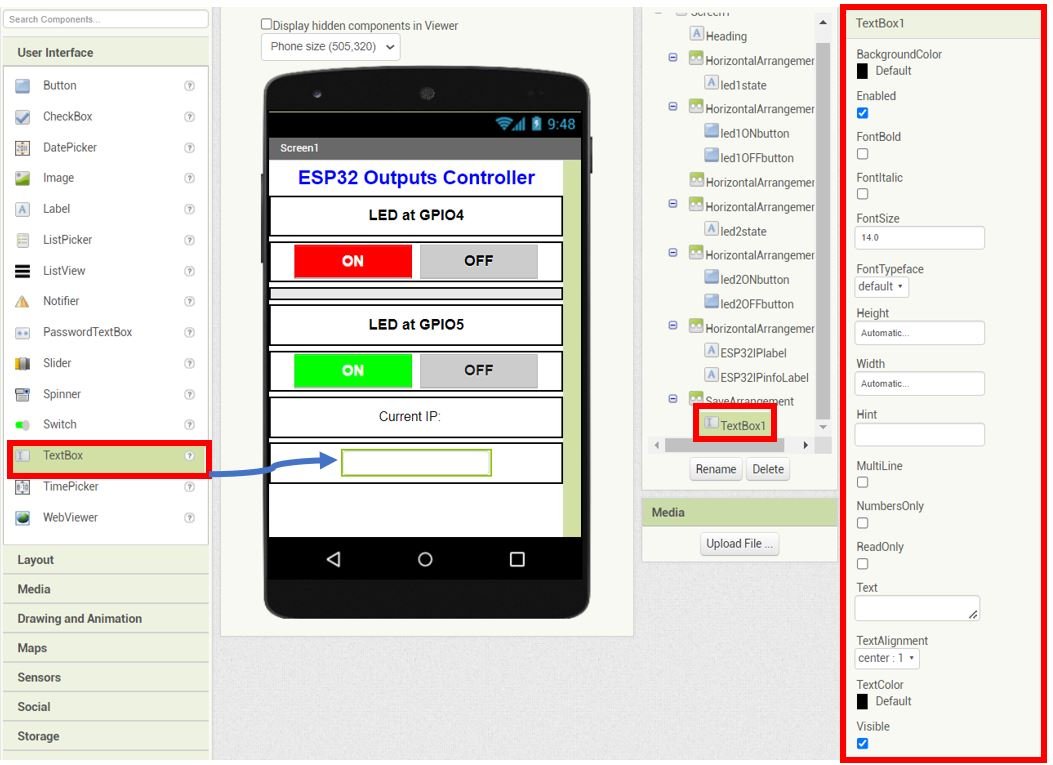
Go to Palette > User Interface and head over to ‘TextBox.’ Now drag and drop it on the Viewer side, inside the SaveArrangement. The Properties section shows the properties we have set for this arrangement.
This is the textbox where the user will enter the IP address of the ESP32 module.
Next add a button beside the textbox as shown below. Rename the button to ‘saveButton‘ and set its properties as shown in the Properties section.

Now un tick the visibility of SaveArrangment.
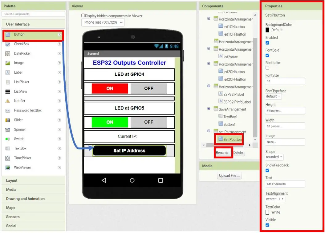
Set IP Address Button
For the ‘Set IP Address’ button, first add a HorizontalArrangement beneath saveArrangement and set its properties as shown.
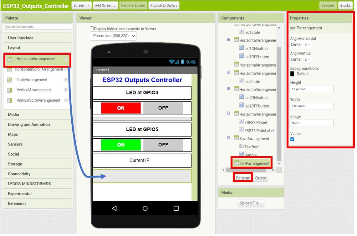
Now place a button inside this horizontal arrangement. Rename it to ‘SetIPbutton‘ and set its properties as shown below:
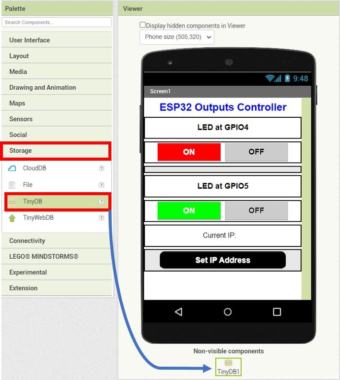
Go to Storage > TinyDB and drag and drop it in the viewer. This is a non-visible component of the app that will store application data such as the IP address of the ESP32 module.
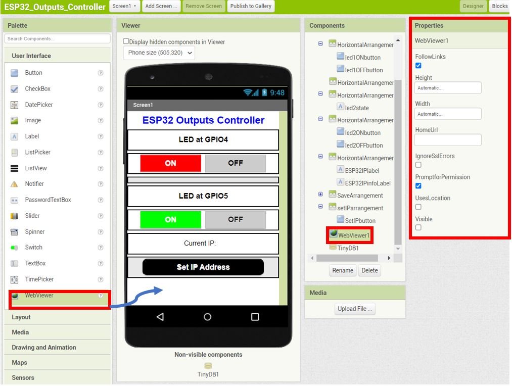
Lastly, go to User Interface > WebViewer and drag and drop it in the viewer. Un tick its visibility.
The WebViewer will be used to access the ESP32 outputs control web server to control the LEDs when the ON/OFF buttons will be clicked.
Blocks Layout
Now click on the ‘Blocks’ button found at the top of the window. A new editor will open up. Here we will design how our app will respond. We will assemble blocks in the workspace by clicking and dragging them.

Setting and Saving IP Address
Firstly, assemble the blocks for the SetIPbutton and saveButon as shown below.
When the SetIPbutton is clicked, the SaveArrangement’s visibility is set to true. This means that the textbox and the Save button will now be visible to the user. However, the setIParrangement’s visibility is turned off.
The user will enter the IP address of the ESP32 module in the text box and press the Save button to save it. When the saveButton is clicked, the IP address gets saved in TinyDB with the tag ‘esp_ip.’ The ESP32IPinfoLabel’s text displays the value saved in the tag ‘esp_ip.’ If the tag is not present yet, then an empty string is shown instead. Moreover, the visibility of SaveArrangement is turned off and the visibility of setIParrangement is turned on.

LED Control
When the led1ONbutton is clicked, the WebViewer accesses the ESP32 outputs control web server by opening the URL set to the IP address of the module joined with /led1ON. The IP address is saved in TinyDB under the tag ‘esp_ip.’ When the user clicks the ON button for led1, the android app opens the URL: http://YOUR_IP_ADDRESS/led1ON. This turns the LED ON.
Next, the state of led1 is also stored in TinyDB under the tag ‘led1state’ with the value ‘LED at GPIO4 is ON.’ The text of led1state is set to the value in the tag led1state saved on TinyDB. If a tag was not present yet, then the text of led1state will be ‘LED at GPIO4.’

When the led1OFFbutton is clicked, the WebViewer accesses the ESP32 outputs control web server by opening the URL set to the IP address of the module joined with /led1OFF. The IP address is saved in TinyDB under the tag ‘esp_ip.’ When the user clicks the OFF button for led1, the android app opens the URL: http://YOUR_IP_ADDRESS/led1OFF. This turns the LED OFF.
Next, the state of led1 is also stored in TinyDB under the tag ‘led1state’ with the value ‘LED at GPIO4 is OFF.’ The text of led1state is set to the value in the tag led1state saved on TinyDB. If a tag was not present yet, then the text of led1state will be ‘LED at GPIO4.’

The same logic is used for led2ONbutton and led2OFFbutton as shown below:.

App Initialization
When the android application is initialized, the text of ESP32IPinfoLabel is set to the value saved in TinyDB in the tag ‘esp_ip’. If no tag is present then an empty string will be displayed. Likewise, the text of led1state is set to the value saved in TinyDB in the tag ‘led1state.’ If no tag is present, the value ‘LED at GPIO4’ is set. Similarly, the text of led2state is set to the value saved in TinyDB in the tag ‘led2state.’ If no tag is present, the value ‘LED at GPIO5’ is set.

For more information regarding building your app in MIT App Inventor, follow this guide: App Inventor Tutorials.
Setting up App Inventor on Smartphone
Now, as we have built our app in MIT app inventor and have also written its code let’s move ahead and install the App Inventor in our smartphone. Through this, we will be able to access our app on our smartphone from anywhere around the world. Follow the steps closely.
Firstly, go to Play Store and install ‘MIT AI2 Companion.’

After you installed the application, open it. You will have to either scan a QR code or type a 6-character code.

To access these, go to MIT App Inventor main page where we initially built our app. Go to Build > Android App (.apk). After a few moments your barcode will get generated. You can either download the .apk file or scan the barcode using the MIT App Inventor.
After installing the .apk file on our android phone, we will be able to view the screen which we created.
Now, we will demonstrate the project.
Demonstration
Make sure you choose the correct board and COM port before uploading your code to the board. Go to Tools > Board and select ESP32 Dev Module. Next, go to Tools > Port and select the appropriate port through which your board is connected.

Click on the upload button to upload the code into the ESP32 development board.
Now, we will upload the files into our ESP32 board. Go to Tools > ESP32 Data Sketch Upload. After a few moments, the files will be uploaded.

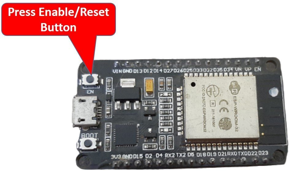
After you have uploaded your code and the files to the ESP32 development board, press its ENABLE button.
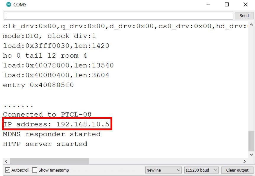
In your Arduino IDE, open up the serial monitor and you will be able to see the IP address of your ESP32 module after it connects with the local Wi-Fi network.
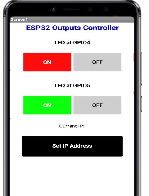
Open the MIT Companion app on your smartphone. Now press the ‘Set IP Address’ button.
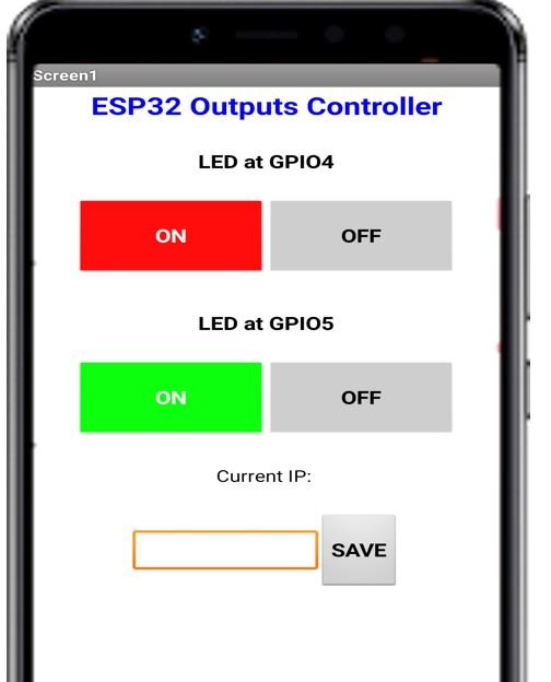
A textbox and Save button will appear.
Type the IP address obtained from the serial monitor in the textbox. Then press the Save button.
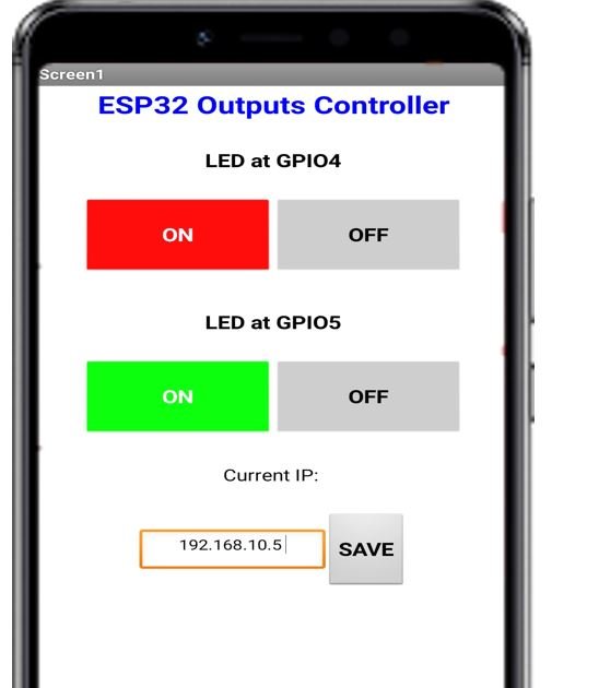
The Current IP address is now updated to the one which we just saved.
Now press the ON/OFF buttons for each LED to control the ESP32 outputs.
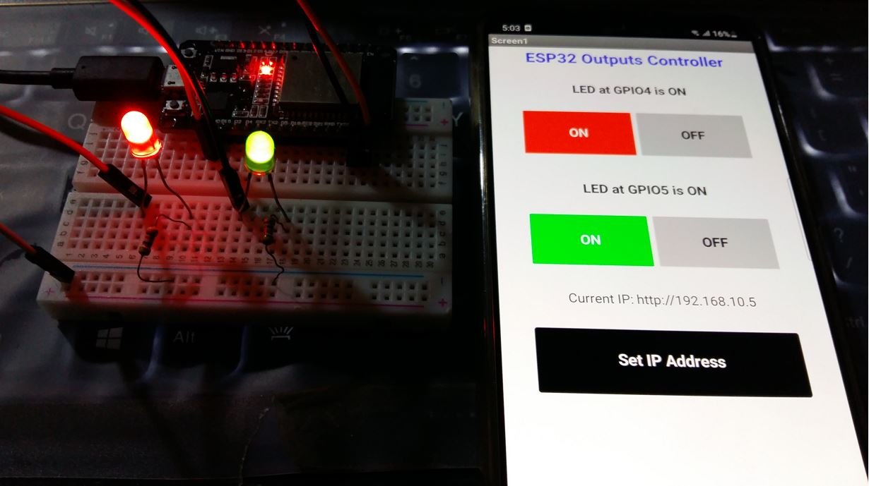
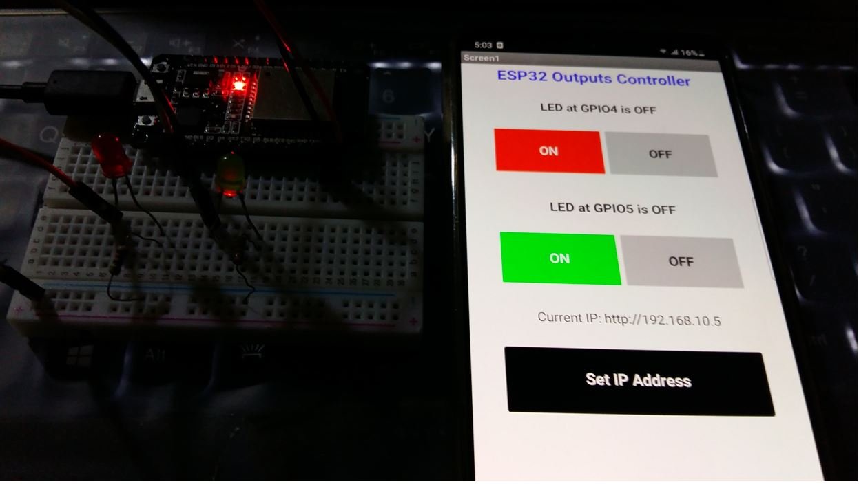
Video demo:
You may also like to read:
- Arduino LED Slider Brightness Control Android App with MIT App Inventor
- ESP8266 Getting Started with Microsoft Azure IoT Central
- Arduino Send Messages from Android to LCD with MIT App Inventor
- Display Sensor Readings in Gauges with ESP32 Web Server
- Arduino RGB LED Control using Android App with MIT App Inventor
- ESP32 Rest API Web Server GET and POST Examples with Postman API
- Arduino Send Sensor Readings to Android app with MIT App Inventor
This is not over the internet, it’s over wifi… would you access your ESP from another network?
looking for MIP APK file of this program. you know the download that should have been included. is it hidden somewhere…
if you send it to me, I will gladly place it on google drive for everyone to use.
Sir Please send code Thanks
C’est un excellent projet.Bravo…
Hi, I have a question. Is this working with a rgb?
We copied your code and replaced everything that consists of digitalWrite with ‘ledcsetup’ ; ledcAttachPin ; ledcWrite because we have an rgb.
and we have expanded the webpage accordingly, because we have an rgb and accordingly have three pins to create our colors.
We also made three more code blocks for our colors (turquoise, yellow, purple) (structured like the on or off block) to activate the colors by pressing a button on the app, which should actually work because we have the webpage exactly the same like the previous web page from your side, we have only added 3 buttons
I hope you can relate to my description
and possibly give me an answer
To access via internet, is it possible to enter the IP address as follows: 89. ……. : 600
either the public IP address of the box (i.e 89. ….) and the external port (i.e 600) after doing a port forwarding in the box to the ESP32?
Hello,
To access from another network, can we make the IP SET with the
address: (i.e.) 89…… : 600 where 89….. is the public address of the box and 600 the redirected port?
Thanks a lot! I’m using it on Arduino Nano Esp32 connected to the phone configured both as Access Point and as Control App and it’s all Ok.
Hello,
with this sketch my ESP32 Dev Module doesn’t connect to the WIFI.
Have tried with another sketches, in AP and STA mode, they do connect to WI FI.
Please advise.
Thank you, Branko
Hello,
this sketch does not connect to WIFI, Serial Monitor shows:
……….ets Jul 29 2019 12:21:46
rst:0x1 (POWERON_RESET),boot:0x13 (SPI_FAST_FLASH_BOOT)
configsip: 0, SPIWP:0xee
clk_drv:0x00,q_drv:0x00,d_drv:0x00,cs0_drv:0x00,hd_drv:0x00,wp_drv:0x00
mode:DIO, clock div:2
load:0x3fff0030,len:4688
load:0x40078000,len:15504
load:0x40080400,len:4
load:0x40080404,len:3196
entry 0x400805a4
…………………………………………………………………………….
”
Have uploaded other sketches ( making AP or STA mode ) and connects to the WIFI.
Please, advice.
Thank you, Branko
I was check this block code and arduino ide it’s worked. Thank you