In this tutorial, we will see how to create a web server using ESP32 and ESP8266 boards to control outputs with a timer. Specifically, we will be controlling an onboard LED using a slider, allowing us to select a specific number of seconds. During this chosen time, the LED will remain in a HIGH state.
This ESP32 project is particularly valuable for electronics projects where we need to activate an LED or relay for a predetermined duration. By incorporating this functionality into our projects, we can easily implement time-based operations and automate various tasks. This level of control can be essential in applications like home automation, smart lighting, or other IoT projects.

Prerequisites:
We will use Arduino IDE to program our ESP32/ESP8266 development board. Thus, you should have the latest version of Arduino IDE. Additionally, you also need to install the ESP32 and the ESP8266 plugin. You can visit the links shown below for better insight.
Recommended Components
The following components are used in this project or are helpful for building it with the ESP32.
| Component | How it’s used in this project | Buy on Amazon |
|---|---|---|
| ESP32 Development Board (DevKit V1) | The main board that runs the project firmware. | Check Price |
| ESP8266 NodeMCU (ESP-12E) | An alternative Wi-Fi board; this tutorial works on the ESP8266 NodeMCU as well. | Check Price |
| Micro USB Cable | Connects the board to your computer to upload code and power it. | Check Price |
| Breadboard | Holds the board and components together while you wire up the project. | Check Price |
| Jumper Wires | Make the connections between the board and any external parts. | Check Price |
| 5mm LED | An external LED on a GPIO pin to demonstrate the timed output control. | Check Price |
| Relay module | Switch a mains load on a timer instead of the onboard LED. | Check Price |
As an Amazon Associate we earn from qualifying purchases. Prices and availability are accurate as of the date/time indicated and are subject to change.
Project Overview
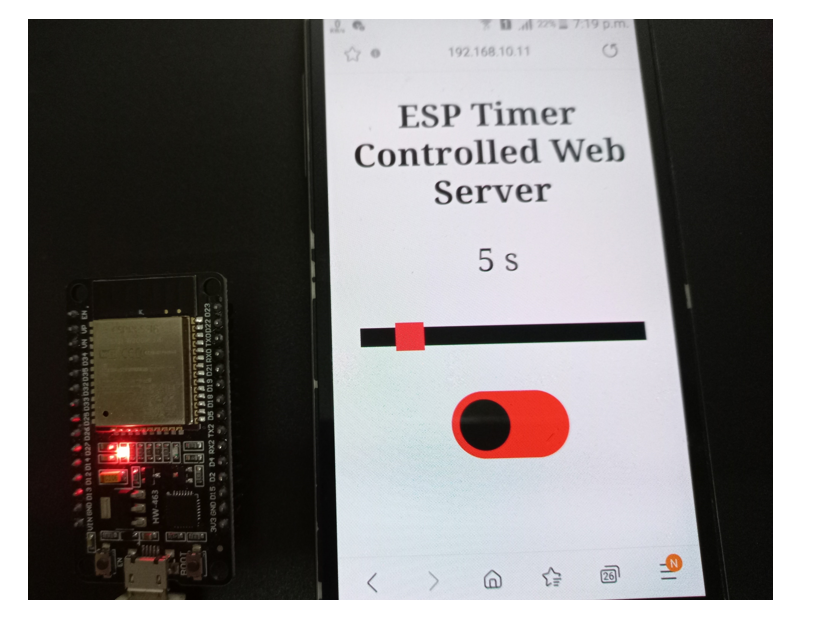
In this guide, we will add a slider (for timer) and a sliding button to an asynchronous web server. The web server will consist of a heading: ESP Timer Controlled Web Server, a slider to set the pulse width, and a sliding button to toggle the LED.

- Firstly, we will upload our Arduino sketch to our ESP board.
- Then, we will receive an IP address in our serial monitor.
- Secondly, we will copy that IP address into a web browser and press enter. The web server will be displayed.
- We will move the slider to set the pulse width. This will be the number of seconds we want our onboard LED to stay in a HIGH state (remain ON).
- Below the slider, you can view a sliding button. You can slide it left/right to control the output of the ESP32/ESP8266 board. This output will be configured through GPIO2 in our program code that corresponds to the onboard LED. Hence, we can toggle the LED through this button ON/OFF button.
- When you click the ON button, the pulse will be sent. The number of seconds will start decreasing automatically. We will be able to see them decrease for the duration of the pulse width which we set.
- After the timer stops, the onboard LED will go back to the LOW state (OFF). The sliding button will also go back to OFF.
- Hence, we can easily set the duration of the timer through the slider and control the ESP32/ESP8266 outputs for a set time.

Recommended readings:
ESP8266 NodeMCU Asynchronous Web Server using Arduino IDE
ESP32 Asynchronous Web Server using Arduino IDE
Setting up Arduino IDE
Installing ESPAsyncWebServer Library and Async TCP/ ESP Async TCP Library
We will need two libraries to build our web server.
- ESPAsyncWebServer & AsyncTCP for ESP32.
- ESPAsyncwebServer & ESPAsyncTCP for ESP8266.
The ESPAsyncWebServer library will help us in creating our web server easily. With this library, we will set up an asynchronous HTTP server. AsyncTCP (for ESP32 only) and ESPAsyncTCP (for ESP8266 only) library will also be incorporated as it is a dependency for the ESPAsyncWebServer library. All of these libraries are not available in the Arduino library manager. Therefore, we will have to download and load them on our ESP32/ESP8266 board ourselves.
For ESP32 & ESP8266
To install the ESPAsyncWebServer library for free, click here to download. You will download the library as a .zip folder which you will extract and rename as ‘ESPAsyncWebServer.’ Then, transfer this folder to the installation library folder in your Arduino IDE.
For ESP32 Only
To install the Async TCP library for free, click here to download. You will download the library as a .zip folder which you will extract and rename as ‘AsyncTCP.’ Then, transfer this folder to the installation library folder in your Arduino IDE.
For ESP8266 Only
To install the ESPAsync TCP library for free, click here to download. You will download the library as a .zip folder which you will extract and rename as ‘ESPAsyncTCP.’ Then, transfer this folder to the installation library folder in your Arduino IDE.
Likewise, you can also go to Sketch > Include Library > Add .zip Library inside the IDE to add the libraries as well. After installation of the libraries, restart your IDE.
ESP32 and ESP8266 Code
Open your Arduino IDE and go to File > New to open a new file. Copy the code given below in that file. Remember to replace the network credentials to ensure a successful connection.
This code is compatible with both ESP32 and ESP8266 boards except for parts where we are defining the state of the LED. For ESP8266, the onboard LED works on an opposite logic as compared to ESP32. To turn the onboard LED ON, a low signal is sent and to turn it OFF, a high signal is sent. This is the opposite in the case of ESP32.
#ifdef ESP32
  #include <WiFi.h>
  #include <AsyncTCP.h>
#else
  #include <ESP8266WiFi.h>
  #include <ESPAsyncTCP.h>
#endif
#include <ESPAsyncWebServer.h>

// Replace with your network credentials
const char* ssid = "PTCL-BB";
const char* password = "44332211";

const char* input_parameter1 = "state";
const char* input_parameter2 = "value";

const int output = 2;

String Timer_Value = "15";

// Create AsyncWebServer object on port 80
AsyncWebServer server(80);

const char index_html[] PROGMEM = R"rawliteral(
<!DOCTYPE HTML><html>
<head>
  <meta name="viewport" content="width=device-width, initial-scale=1">
  <title>ESP Web Server</title>
  <style>
    html {font-family: Times New Roman; display: inline-block; text-align: center;}
    h2 {font-size: 2.4rem;}
    p {font-size: 2.2rem;}
    body {max-width: 600px; margin:0px auto; padding-bottom: 25px;}
    .switch {position: relative; display: inline-block; width: 120px; height: 68px}
    .switch input {display: none}
    .slider {position: absolute; top: 0; left: 0; right: 0; bottom: 0; background-color: #FF0000; border-radius: 34px}
    .slider:before {position: absolute; content: ""; height: 52px; width: 52px; left: 8px; bottom: 8px; background-color: #212420; -webkit-transition: .4s; transition: .4s; border-radius: 68px}
    input:checked+.slider {background-color: #44f321}
    input:checked+.slider:before {-webkit-transform: translateX(52px); -ms-transform: translateX(52px); transform: translateX(52px)}
    .slider2 { -webkit-appearance: none; margin: 14px; width: 300px; height: 20px; background:  #000000;
      outline: none; -webkit-transition: .2s; transition: opacity .2s;}
    .slider2::-webkit-slider-thumb {-webkit-appearance: none; appearance: none; width: 30px; height: 30px; background: #ff0825; cursor: pointer;}
    .slider2::-moz-range-thumb { width: 30px; height: 30px; background: #2f4468; cursor: pointer; }
  </style>
</head>
<body>
  <h2>ESP Timer Controlled Web Server</h2>
  <p><span id="timer">%timer%</span> s</p>
  <p><input type="range" onchange="updateSliderTimer(this)" id="Timer_slider" min="1" max="30" value="%timer%" step="1" class="slider2"></p>
  %BUTTONPLACEHOLDER%
<script>
function toggleCheckbox(element) {
  var sliderValue = document.getElementById("Timer_slider").value;
  var xhr = new XMLHttpRequest();
  if(element.checked){ xhr.open("GET", "/update?state=1", true); xhr.send();
    var count = sliderValue, timer = setInterval(function() {
      count--; document.getElementById("timer").innerHTML = count;
      if(count == 0){ clearInterval(timer); document.getElementById("timer").innerHTML = document.getElementById("Timer_slider").value; }
    }, 1000);
    sliderValue = sliderValue*1000;
    setTimeout(function(){ xhr.open("GET", "/update?state=0", true);
    document.getElementById(element.id).checked = false; xhr.send(); }, sliderValue);
  }
}
function updateSliderTimer(element) {
  var sliderValue = document.getElementById("Timer_slider").value;
  document.getElementById("timer").innerHTML = sliderValue;
  var xhr = new XMLHttpRequest();
  xhr.open("GET", "/slider?value="+sliderValue, true);
  xhr.send();
}
</script>
</body>
</html>
)rawliteral";

// Replaces placeholder with button section in your web page
String processor(const String& var){
  //Serial.println(var);
  if(var == "BUTTONPLACEHOLDER"){
    String buttons = "";
    String outputStateValue = outputState();
    buttons+= "<p><label class=\"switch\"><input type=\"checkbox\" onchange=\"toggleCheckbox(this)\" id=\"output\" " + outputStateValue + "><span class=\"slider\"></span></label></p>";
    return buttons;
  }
  else if(var == "timer"){
    return Timer_Value;
  }
  return String();
}

String outputState(){
  if(digitalRead(output)){
    return "checked";
  }
  else {
    return "";
  }
  return "";
}

void setup(){
  // Serial port for debugging purposes
  Serial.begin(115200);

  pinMode(output, OUTPUT);
  digitalWrite(output, LOW);

  // Connect to Wi-Fi
  WiFi.begin(ssid, password);
  while (WiFi.status() != WL_CONNECTED) {
    delay(1000);
    Serial.println("Connecting to WiFi..");
  }

  // Print ESP Local IP Address
  Serial.println(WiFi.localIP());

  // Route for root / web page
  server.on("/", HTTP_GET, [](AsyncWebServerRequest *request){
    request->send_P(200, "text/html", index_html, processor);
  });


  server.on("/update", HTTP_GET, [] (AsyncWebServerRequest *request) {
    String message;
    // GET input1 value on <ESP_IP>/update?state=<message>
    if (request->hasParam(input_parameter1)) {
      message = request->getParam(input_parameter1)->value();
      digitalWrite(output, message.toInt());
    }
    else {
      message = "There is no message!";
    }
    Serial.println(message);
    request->send(200, "text/plain", "OK");
  });

  server.on("/slider", HTTP_GET, [] (AsyncWebServerRequest *request) {
    String message;
    // GET input1 value on <ESP_IP>/slider?value=<message>
    if (request->hasParam(input_parameter2)) {
      message = request->getParam(input_parameter2)->value();
      Timer_Value = message;
    }
    else {
      message = "No message sent";
    }
    Serial.println(message);
    request->send(200, "text/plain", "OK");
  });

  // Start server
  server.begin();
}

void loop() {

}
How does the Code Work?
We have already covered in previous tutorials how to build an asynchronous web server with sliding buttons to control the outputs of the ESP32/ESP8266 module. In this case, we will include a timer inside our web server. The duration of the timer will determine the number of seconds the onboard LED will remain in a HIGH state. Thus, we will only focus on newer relevant parts of the code where the timer is being incorporated because the rest of the parts are already covered before.
Importing Libraries
Firstly, we will import all the necessary libraries which are required for this project. As this code is compatible with both ESP32 and ESP8266 thus both libraries (WiFi.h and ESP8266WiFi.h) are defined. This library will help in establishing the connection between our ESP module to a wireless network. We will also import the two libraries which we installed previously, the ESPAsyncWebServer library and the ESPAsyncTCP library.
#ifdef ESP32
  #include <WiFi.h>
  #include <AsyncTCP.h>
#else
  #include <ESP8266WiFi.h>
  #include <ESPAsyncTCP.h>
#endif
#include <ESPAsyncWebServer.h>
Setting Network Credentials
Next, we will create two global variables, one for the SSID and the other for the password. These will hold our network credentials which will be used to connect to our wireless network. Replace both of them with your credentials to ensure a successful connection.
const char* ssid = "ENTER_YOUR_WIFI_NAME";
const char* password = "ENTER_YOUR_WIFI_PASSWORD";
Setting Input Parameters
We will pass two global variables of type char. These will be the input parameters which we will use. One parameter is the state (HIGH or LOW) . The other is the ‘value’ of the timer also known as the slider value.
const char* input_parameter1 = "state";
const char* input_parameter2 = "value";
Slider Action
In our web server, we have a slider that can be moved either way. We will use it to set a pulse width or timer according to our needs.
Slider Value
Above the slider, you will be able to view the current slider value. This value will be the number of seconds we want the LED to remain ON.
<p><span id="timer">%timer%</span> s</p>As you can see above, we have used the %timer% placeholder to denote this current value. After upload, this value will be replaced by the value which we stored in a string variable called ‘Timer_value’. We set that value to 15. You can use any other value according to your preference. So, when the webserver will load the %timer% placeholder will get replaced by the value ‘15’. This will be the initial current slider value which will be first seen by the user.
String Timer_Value = "15";By sliding the slider right and left the user will be able to increase/decrease this value.
Creating Slider
<p><input type="range" onchange="updateSliderTimer(this)" id="Timer_slider" min="1" max="30" value="%timer%" step="1" class="slider2"></p>The above line of code will create the slider on our webserver. As you may notice the slider represents an input type in HTML. Thus, we have specified it inside the tag where the user will be able to enter some type of data. Further, the slider is identified as input field type ‘range’. This represents the range of the data that will be associated with the slider. We will call the updateSliderTimer() function and specify it in the onchange property. This will occur when the user will move the slider. Next in the ‘id’ attribute, we will specify ‘Timer_slider’ as the unique id to our slider.
We will use the following properties to specify the range in our slider:
- min: This corresponds to the minimum value of the data. We are specifying it as 1.
- max: This corresponds to the maximum value of the data. We are specifying it as 30.
- value: This corresponds to the slider value which we have specified as %timer%. Remember this was the placeholder that gets replaced by the string ‘Timer_Value’ which we set to ‘15’.
- step: This corresponds to the interval between consecutive numbers. We have set it to 1. Thus values can be incremented/decremented by ±1.
Thus the range of values which is the time can be from 1-30 seconds. You can specify any valid range of the timer according to your needs.
Updating the Slider Value through updateSliderTimer()
To update the value of the slider we will call the updateSliderTimer() function. This takes in a single argument called ‘element’. Whenever the user will move the slider on the webpage the following function will do its job.
function updateSliderTimer(element) {
  var sliderValue = document.getElementById("Timer_slider").value;
  document.getElementById("timer").innerHTML = sliderValue;
  var xhr = new XMLHttpRequest();
  xhr.open("GET", "/slider?value="+sliderValue, true);
  xhr.send();
}
As you can see above, the current slider value is obtained by referring to the ‘id’ of the slider (Timer_slider) which we specified when creating the slider. This value is then updated to the value saved in the Timer_slider id.
var sliderValue = document.getElementById("Timer_slider").value;
document.getElementById("timer").innerHTML = sliderValue;
Inside this function, we use the XMLHttpRequest. This will allow us to make an HTTP request in JavaScript.
To make the HTTP GET request, we will follow three steps:
Firstly, we will create an XMLHttpRequest as follows:
var xhr = new XMLHttpRequest();Secondly, we will initialize the request by using the xhr.open() method. Inside it we will pass on three arguments. The first argument specifies the type of HTTP method which is GET in our case. The second argument is the URL to which are ESP32/ESP8266 will request upon. In our case, it is the /slider?value=sliderValue URL. The last argument is true which specifies that the request is asynchronous.
xhr.open("GET","/slider?value="+sliderValue, true);
Lastly, we will use xhr.send() to open the connection. Our server (ESP32/ESP8266) will now be able to receive the HTTP GET request whenever the sliding button will be moved.
xhr.send();Controlling Output through toggleCheckbox() function
function toggleCheckbox(element) {
  var sliderValue = document.getElementById("Timer_slider").value;
  var xhr = new XMLHttpRequest();
  if(element.checked){ xhr.open("GET", "/update?state=1", true); xhr.send();
    var count = sliderValue, timer = setInterval(function() {
      count--; document.getElementById("timer").innerHTML = count;
      if(count == 0){ clearInterval(timer); document.getElementById("timer").innerHTML = document.getElementById("Timer_slider").value; }
    }, 1000);
    sliderValue = sliderValue*1000;
    setTimeout(function(){ xhr.open("GET", "/update?state=0", true);
    document.getElementById(element.id).checked = false; xhr.send(); }, sliderValue);
  }
}
We will use JavaScript to create the toggleCheckBox() function that checks for the correct toggle feature of our sliding button through an if-else statement. The current slider value is obtained by accessing the ‘Timer_slider’ id.
var sliderValue = document.getElementById("Timer_slider").value;Then it will create the HTTP GET request whenever a button will be slid over inside the if statement. For the first ‘if’ statement, the request is made on the /update?state=1 URL. The ESP32/ESP8266 will have to set the ouput to HIGH as the state is ‘1’.
var xhr = new XMLHttpRequest();
if(element.checked){ xhr.open("GET", "/update?state=1", true);
xhr.send();
Next, we also have to incorporate the timer. Thus, the following lines of code will decrement the slider value after every second. This will generate the countdown time effect.
    var count = sliderValue, timer = setInterval(function() {
      count--; document.getElementById("timer").innerHTML = count;
      if(count == 0){ clearInterval(timer); document.getElementById("timer").innerHTML = document.getElementById("Timer_slider").value; }
    }, 1000);
Now, as we know that when the timer will stop then the slider value will return to its initial one. The onboard LED will also turn OFF. Thus, we will make a GET request on the /update?state=0 URL. The ESP32/ESP8266 board will then set the output to LOW as the state is ‘0’. The sliding button also returns to its initial OFF state which we distinguished in red colour in our CSS styling.
setTimeout(function(){ xhr.open("GET", "/update?state=0", true);
document.getElementById(element.id).checked = false; xhr.send(); }, sliderValue);
  }
ESP32/ESP8266 Handling Requests
In this section, we will discuss how our ESP board will handle the requests on the different URLs.
/root URL
Firstly, we will deal with the /root URL request which the ESP board will receive.
We will use the send_P() method. The handling function will respond to the client by using the send_P() method on the request object. This method will take in four parameters. The first is 200 which is the HTTP status code for ‘ok’. The second is “text/html” which will correspond to the content type of the response. The third input is the text saved on the index_httml variable which will be sent. Finally, the last parameter is the processor function in which all the placeholders will be replaced by their current values.
server.on("/", HTTP_GET, [](AsyncWebServerRequest *request){
    request->send_P(200, "text/html", index_html, processor);
  });
/update URL
Secondly, we will deal with the /update?state=1 URL and /update?state=0 URL received by the ESP board.
server.on("/update", HTTP_GET, [] (AsyncWebServerRequest *request) {
    String message;
    if (request->hasParam(input_parameter1)) {
      message = request->getParam(input_parameter1)->value();
      digitalWrite(output, message.toInt());
    }
    else {
      message = "There is no message!";
    }
    Serial.println(message);
    request->send(200, "text/plain", "OK");
  });
We will use the on() method on the server object to listen to the incoming HTTP requests and execute functions accordingly. The output state of GPIO2 will be accordingly set to either HIGH or LOW. This will be monitored through the two if statements which will check for the two input parameters which we initially defined in the code. Through the digitalWrite() function the output state will be updated.
digitalWrite(output, message.toInt());The send() method will be used to return the HTTP response. It takes in three parameters. The first parameter is the response code which we will specify as 200. It is the HTTP response code for ok. The second parameter is the content type of the response which we will specify as “text/plain” and the third parameter is the actual message which we will be sent as the HTTP response. This is set as “OK”. The arrow operator will be used to call the send method on the AsyncWebServerRequest object.
request->send(200, "text/plain", "OK");/slider URL
Lastly, we will deal with how the ESP board responds to requests received on the /slider URL. This will occur whenever the slider will be moved and a new slider value will be generated. This new slider value will get saved in the variable ‘message’. The value will get printed on our serial monitor.
server.on("/slider", HTTP_GET, [] (AsyncWebServerRequest *request) {
    String message;

    if (request->hasParam(input_parameter2)) {
      message = request->getParam(input_parameter2)->value();
      Timer_Value = message;
    }
    else {
      message = "No message sent";
    }
    Serial.println(message);
    request->send(200, "text/plain", "OK");
  });
Demonstration
Make sure you choose the correct board and COM port before uploading your code to the board. Go to Tools > Board and select ESP32 Dev Module or ESP8266 Module.

Next, go to Tools > Port and select the appropriate port through which your board is connected.

Click on the upload button to upload the code into the ESP32/ESP8266 development board.
After you have uploaded your code to the development board, press its ENABLE button.

In your Arduino IDE, open up the serial monitor and you will be able to see the IP address of your ESP module.

Type that IP address in a web browser and press enter.

Now, move the slider and change the pulse width. Press the ON/OFF button. Simultaneously the onboard LED will light up and the timer will start decreasing. When the timer stops the sliding button will return to LOW state and the LED will turn OFF.

You can also see a short video of the demo below:
Conclusion
In conclusion, we have successfully created an asynchronous web server capable of controlling ESP32/ESP8266 outputs based on a timer. Throughout this project, we used GPIO2 to connect to the onboard LED for simplicity, but it’s essential to note that the program code can be easily adapted to control other output GPIOs as needed. We can extend the application to control various devices and create more complex projects based on this web server. By leveraging this web server and timer control system, we can implement automation and remote control functionalities in our ESP32/ESP8266 projects.
Related ESP32 and ESP8266 web server projects:
- ESP8266 NodeMCU WebSocket Server using Arduino IDE and LittleFS – Control GPIOs
- ESP8266 NodeMCU Asynchronous Web Server using Arduino IDE and ESPAsyncWebServer library
- ESP32 WebSocket Server using Arduino IDE – Control GPIOs and Relays
- ESP32/ESP8266 HTTP Authentication Web Server (Username and Password Protected)
- ESP32 Asynchronous Web Server using Arduino IDE and ESPAsyncWebServer library
- ESP8266 NodeMCU Web Server using LittleFS (Flash File System)
- ESP32 Web Server with SPIFFS (SPI Flash File System)
hello
how to add eeprom to this sketch so the countdown will automatically start when start (after blackout etc)
i already add eeprom based on my knowledge and success the upload code but when booting it error
————— CUT HERE FOR EXCEPTION DECODER —————
ets Jan 8 2013,rst cause:2, boot mode:(3,6)
load 0x4010f000, len 3460, room 16
tail 4
chksum 0xcc
load 0x3fff20b8, len 40, room 4
tail 4
chksum 0xc9
csum 0xc9
v0004a210
~ld
can you help?
btw sorry i use other web to put my code since when i put in this comment box the system decline it.