In this tutorial, we will learn about MAX30102 high sensitivity pulse oximeter and heart rate sensor and how to interface it with ESP32 development board to measure BPM and blood oxygen concentration (SpO2). This sensor is used to measure heartbeat/pulse rate in BPM and blood oxygen concentration (SpO2) in percentage. Firstly, we will discuss the introduction, pinout, working, and connection diagram of the sensor with ESP32. After that, we will see different examples sketches from the SparkFun MAX3010x Pulse and Proximity Sensor Library. These will include finding BPM reading, plotting raw data on serial plotter, presence sensing, and temperature measurement. So let us begin!
We have similar guides with Arduino Uno and ESP8266 NodeMCU:
- MAX30102 Pulse Oximeter and Heart Rate Sensor with Arduino
- MAX30102 Pulse Oximeter and Heart Rate Sensor with ESP8266
Recommended Components
The following components are used in this project or are helpful for building it with the ESP32.
| Component | How it’s used in this project | Buy on Amazon |
|---|---|---|
| ESP32 Development Board | Reads the pulse oximeter sensor over I2C and processes the BPM and SpO2 values. | Check Price |
| Micro USB Cable | Programs the ESP32 and powers it during testing. | Check Price |
| Breadboard | Holds the sensor and wiring without soldering. | Check Price |
| Jumper Wires | Connect the I2C SDA/SCL and power lines to the sensor. | Check Price |
As an Amazon Associate we earn from qualifying purchases. Prices and availability are accurate as of the date/time indicated and are subject to change.
MAX30102 Pulse Oximeter Sensor Introduction
The MAX30102 sensor is the further optimized version of MAX30100 sensor; used as both a heart rate monitor and a pulse oximeter. These features are enabled by constructing this sensor which consists of two LEDs, a photodetector, optimized optics, and low noise signal processing components. It is easily used with microcontrollers such as Arduino, ESP32, ESP8266 NodeMCU, etc. to build an efficient heartbeat and oxygen saturation device.
Below you can view the diagram of MAX30102 Module:

As you may notice the MAX30102 IC lies at the center of the module. The module consists of two different types of LEDs (Red and IR) and a photodetector. Blood oxygen saturation and heart rate are found using these two key features. We will later learn how the sensor actually works to obtain the BPM and SpO2 readings.
Another important feature you may notice is that the MAX30102 sensor module consists of two LDO regulators. This is because the MAX30100 IC requires 1.8V and the LEDs require 3.3V to function properly. With the addition of the voltage regulators, we can safely use microcontrollers that use 5/3.3/1.8V level input/outputs.
Moreover, if you view the module from the back, you can view a solder jumper to select the voltage logic level. By default, it is set to 3.3V but you can also change it to 1.8V according to your microcontroller’s logic requirements.

Key Features
- The MAX30102 sensor module has an ultra low power operation, uses 600μA (measurement mode and 0.7μA(standby mode). Therefore a great choice to use in wearable devices such as smartwatches etc.
- It has a high sample rate capability along with fast data output capability.
- Additionally, the sensor features integrated ambient light cancellation as well.
- One additional feature that the MAX30102 sensor module possess is the inclusion of an on-chip temperature sensor. This gives us the die temperature (-40˚C to +85˚C) which is ± 1˚C accurate.
- For communicating with microcontrollers, the sensor uses the I2C pins SCL and SDA.
- Another feature of this sensor is that it uses a 32 sample FIFO buffer to store data as compared to MAX30100 which has only 16 sample FIFO buffer. In other words, it further reduces power consumption as it already holds maximum of thirty-two heart rate and SPO2 values.
- The MAX30102 can also be used with interrupts which can be enabled for several sources such as power ready, new data ready, ambient light cancellation, temperature ready and FIFO almost full. With the generation of interrupts, the microcontroller can perform other events which do not happen during the sequential execution of a program while the sensor keeps obtaining new data samples.
The table below shows the specifications of this sensor:
| Maximum Current Consumption | 6mA |
| Voltage | 3.3-5V |
| Sample Rate | 50Hz – 3200Hz |
| Temperature Range | -40°C to +85°C |
| Temperature Accuracy | ±1˚C |
| ADC Resolution | 18 bits |
| IR LED peak wavelength | 880nm |
| Red LED peak wavelength | 660nm |
For more information about the specifications, refer to the MAX30102 Datasheet.
MAX30102 Pulse Oximeter Sensor Working
In this section, let us discuss how the MAX30102 heartbeat monitor and pulse oximeter actually works.
Pulse Oximeter
To find the blood oxygen concentration (%), it is first important to know that inside our blood hemoglobin is responsible for carrying oxygen. When a person holds a pulse oximeter, light from the device passes through the blood in the fingers. This is used to detect the amount of oxygen by measuring the changes in light absorption in both oxygenated and deoxygenated blood.
As we already mentioned before, the MAX30102 sensor consists of two LEDs (Red and IR) and a photodiode. Both of these LEDs are used for SpO2 measurement. These two LEDs emit lights at different wavelengths, ~660nm for the red led and ~880nm for the IR LED. At these particular wavelengths, the oxygenated and deoxygenated hemoglobin have vastly different absorption properties.
The diagram below is taken from the datasheet of MAX30100 IC. You may notice the difference shown in the graph between HbO2 which is oxygenated hemoglobin and Hb which is deoxygenated hemoglobin at two different wavelengths.
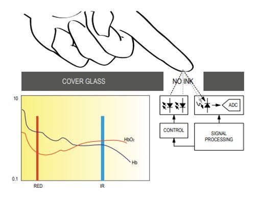
The oxygenated hemoglobin absorbs more infrared light and reflects back the red light whereas the deoxygenated hemoglobin absorbs more red light and reflects back the infrared light. The reflected light is measured by the photodetector. The MAX30102 sensor reads these different absorption levels to find the blood oxygen concentration (SpO2). The ratio of IR and RED light received by the photodetector gives us the blood oxygen concentration.
Heart Rate Measurement
To measure the heart rate, we do not require the Red LED, only the IR LED is needed. This is because oxygenated hemoglobin absorbs more infrared light.
The heartbeat rate is the ratio of time between two consecutive heartbeats. Similarly, when the human blood is circulated in the human body then this blood is squeezed in capillary tissues. As a result, the volume of capillary tissues is increased but this volume is decreased after each heartbeat. This change in volume of capillary tissues affects the infrared light of the sensor, which transmits light after each heartbeat.
The working of this sensor could be checked by placing a human finger in front of this sensor. When a finger is placed in front of this pulse sensor then the reflection of infrared light is changed based on the volume of blood change inside capillary vessels. This means during the heartbeat, the volume of blood in capillary vessels will be high and then will be low after each heartbeat. So, by changing this volume, the LED light is changed. This change of the LED light measures the heartbeat rate of a finger. This phenomenon is known as “Photoplethysmogram.”
MAX30102 Pulse Oximeter Sensor Pinout
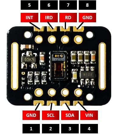
The MAX30102 module consists of eight pins.
| Pin | Description |
|---|---|
| VIN | This pin is used to supply power to the sensor. This sensor is powered on at 3.3-5V. |
| SCL | This is the I2C serial clock pin. |
| SDA | This is the I2C serial data pin. |
| INT | This is the active low interrupt pin. It is pulled HIGH by the onboard resistor but when an interrupt occurs it goes LOW until the interrupt clears. |
| IRD | IR LED Cathode and LED Driver Connection Point |
| RD | Red LED Cathode and LED Driver Connection Point |
| GND | This is used for supplying ground to this sensor and it is connected to the source ground pin. |
Interfacing MAX30102 Sensor with ESP32
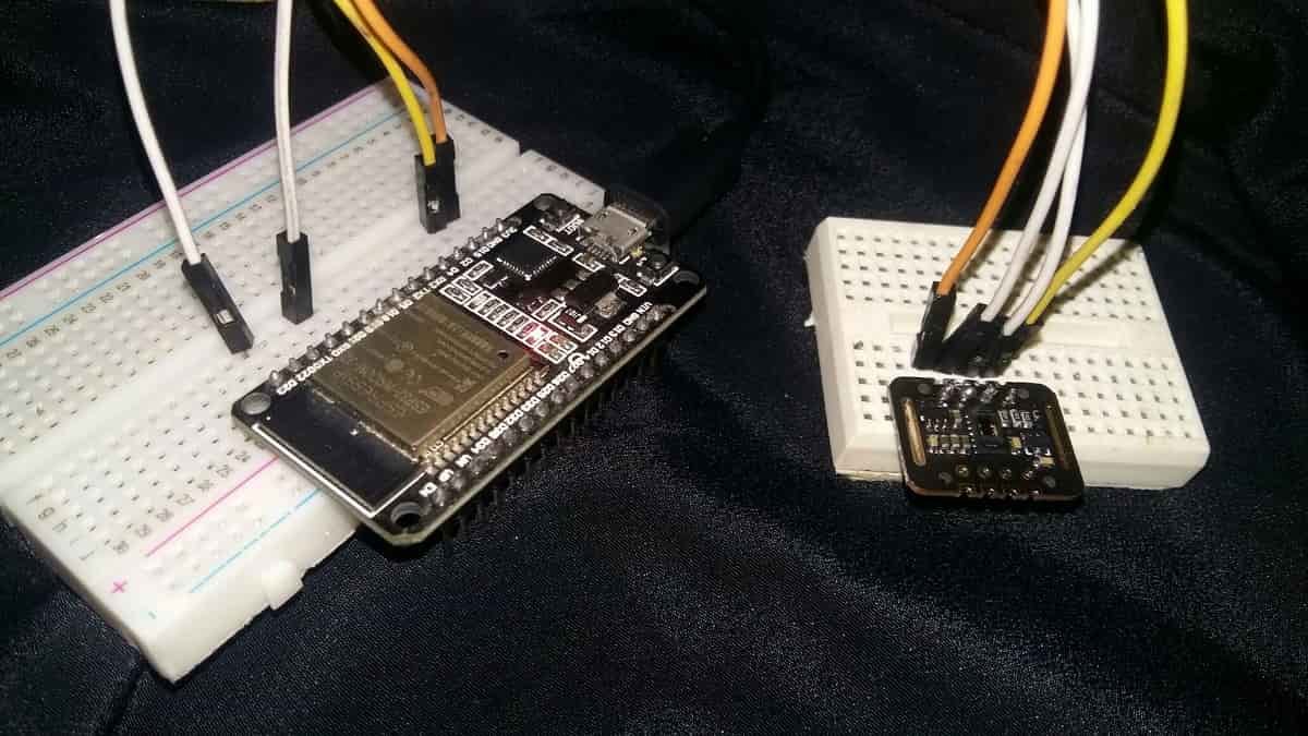
In this section, we will learn how to interface MAX30102 sensor module with ESP32. We will use only four pins of the sensor module to connect with our microcontroller.
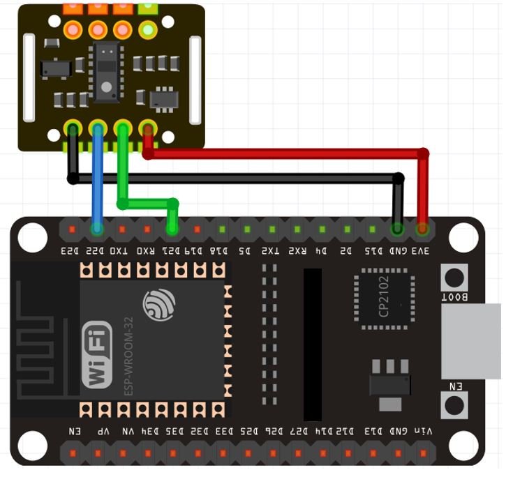
The connections between the sensor module and ESP32 are as follows:
| MAX30102 Module | ESP32 |
|---|---|
| VCC | 3.3V |
| SCL | GPIO22 |
| SDA | GPIO21 |
| GND | GND |
Connect the default I2C pins of ESP32 with the SCL and SDA pins of the module. Additionally, the sensor is powered by 3.3V from the ESP32 and both grounds are in common.
Installing MAX30102 Library in Arduio IDE
We will use Arduino IDE to program our ESP32. Thus, you should have the latest version of Arduino IDE. Additionally, you also need to install the ESP32 plugin.
If your IDE does not have the plugin installed you can visit the link below: Installing ESP32 library in Arduino IDE and upload code.
Open Arduino IDE and click on Sketch > Library > Manage Libraries
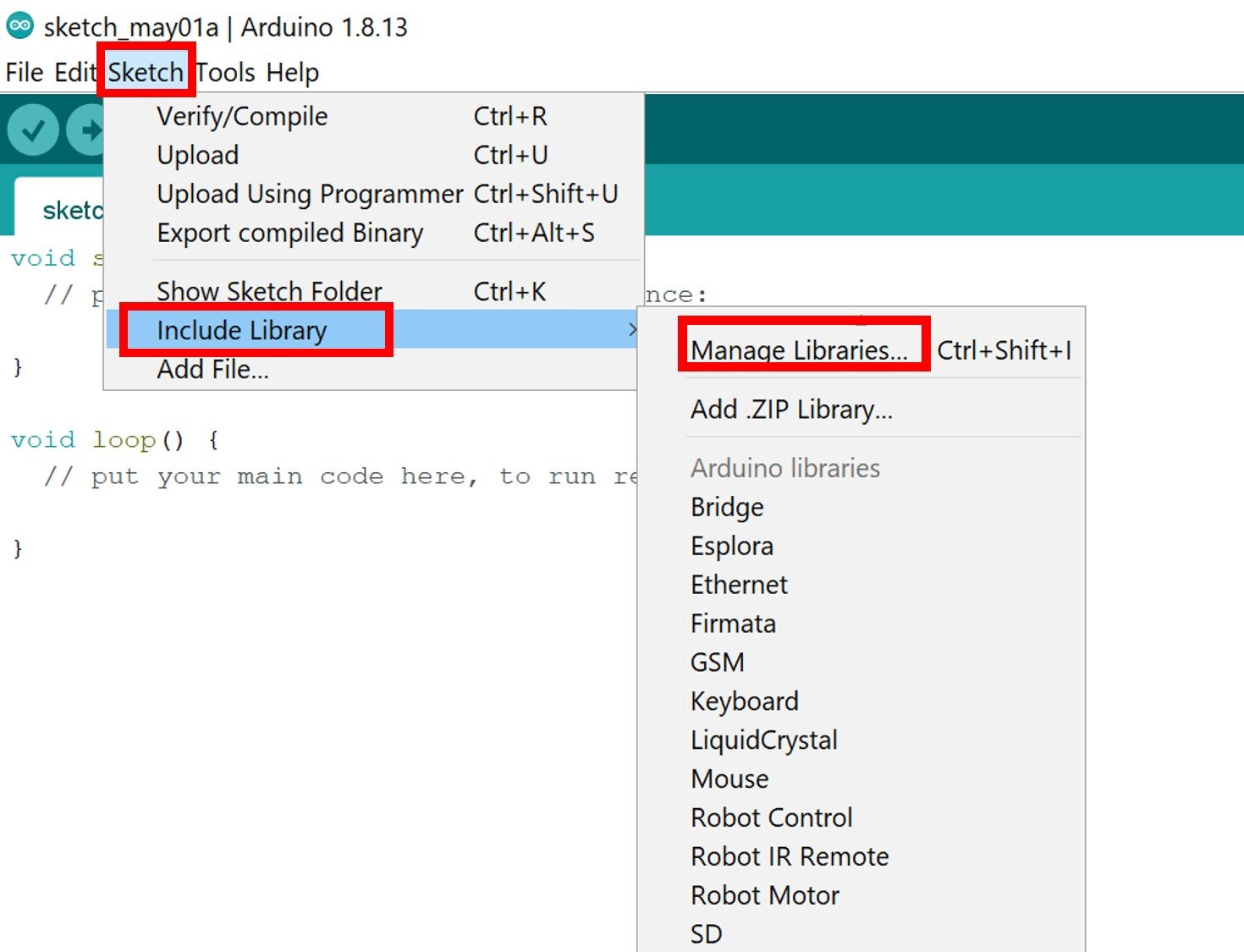
The following window will open up.

Type ‘MAX3010x’ in the search bar and press enter. Install the latest version of the SparkFun MAX3010x Pulse and Proximity Sensor Library.

After installation of the library, restart your IDE.
ESP32 MAX30102 Example Sketches
In this section, we will show you how to use some example sketches available in the Arduino IDE for the SparkFun MAX3010x Pulse and Proximity Sensor library that we just installed. We will look at different examples to effectively learn how to use the sensor with our ESP32.
Measure Heart Rate(BPM) with ESP32 and MAX30102
Open your Arduino IDE and go to File > Examples > SparkFun MAX3010x Pulse and Proximity Sensor Library > Example5_HeartRate.
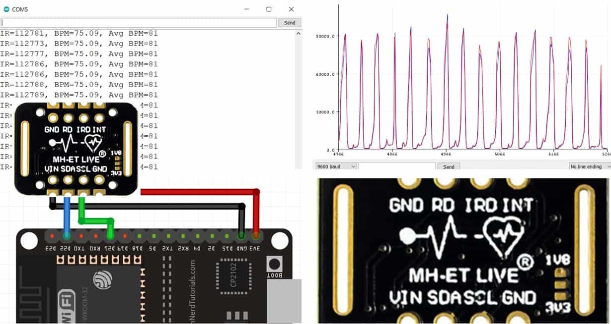
The following program code will open. This example sketch will display the BPM values in the serial monitor when you hold the sensor in between your fingers.
/*
  Optical Heart Rate Detection (PBA Algorithm) using the MAX30105 Breakout
  By: Nathan Seidle @ SparkFun Electronics
  Date: October 2nd, 2016
  https://github.com/sparkfun/MAX30105_Breakout

  This is a demo to show the reading of heart rate or beats per minute (BPM) using
  a Penpheral Beat Amplitude (PBA) algorithm.

  It is best to attach the sensor to your finger using a rubber band or other tightening
  device. Humans are generally bad at applying constant pressure to a thing. When you
  press your finger against the sensor it varies enough to cause the blood in your
  finger to flow differently which causes the sensor readings to go wonky.

  Hardware Connections (Breakoutboard to Arduino):
  -5V = 5V (3.3V is allowed)
  -GND = GND
  -SDA = A4 (or SDA)
  -SCL = A5 (or SCL)
  -INT = Not connected

  The MAX30105 Breakout can handle 5V or 3.3V I2C logic. We recommend powering the board with 5V
  but it will also run at 3.3V.
*/

#include <Wire.h>
#include "MAX30105.h"

#include "heartRate.h"

MAX30105 particleSensor;

const byte RATE_SIZE = 4; //Increase this for more averaging. 4 is good.
byte rates[RATE_SIZE]; //Array of heart rates
byte rateSpot = 0;
long lastBeat = 0; //Time at which the last beat occurred

float beatsPerMinute;
int beatAvg;

void setup()
{
  Serial.begin(115200);
  Serial.println("Initializing...");

  // Initialize sensor
  if (!particleSensor.begin(Wire, I2C_SPEED_FAST)) //Use default I2C port, 400kHz speed
  {
    Serial.println("MAX30102 was not found. Please check wiring/power. ");
    while (1);
  }
  Serial.println("Place your index finger on the sensor with steady pressure.");

  particleSensor.setup(); //Configure sensor with default settings
  particleSensor.setPulseAmplitudeRed(0x0A); //Turn Red LED to low to indicate sensor is running
  particleSensor.setPulseAmplitudeGreen(0); //Turn off Green LED
}

void loop()
{
  long irValue = particleSensor.getIR();

  if (checkForBeat(irValue) == true)
  {
    //We sensed a beat!
    long delta = millis() - lastBeat;
    lastBeat = millis();

    beatsPerMinute = 60 / (delta / 1000.0);

    if (beatsPerMinute < 255 && beatsPerMinute > 20)
    {
      rates[rateSpot++] = (byte)beatsPerMinute; //Store this reading in the array
      rateSpot %= RATE_SIZE; //Wrap variable

      //Take average of readings
      beatAvg = 0;
      for (byte x = 0 ; x < RATE_SIZE ; x++)
        beatAvg += rates[x];
      beatAvg /= RATE_SIZE;
    }
  }

  Serial.print("IR=");
  Serial.print(irValue);
  Serial.print(", BPM=");
  Serial.print(beatsPerMinute);
  Serial.print(", Avg BPM=");
  Serial.print(beatAvg);

  if (irValue < 50000)
    Serial.print(" No finger?");

  Serial.println();
}
Demonstration
Choose the correct board and COM port before uploading your code to the board.
Go to Tools > Board and select ESP32 Dev Module.

Next, go to Tools > Port and select the appropriate port through which your board is connected.

Click on the upload button to upload the code into the ESP32 development board. After you have uploaded your code to the ESP32 development board press its ENABLE button.

Open the serial monitor and set the baud rate to 115200. Hold the sensor in between your fingers. Do not hold it very tightly or very lightly. Make sure you apply normal pressure while holding the sensor. This will result in a better clean signal.
The BPM readings will continuously update to new ones.

Measure Blood Oxygen Concentration (SpO2) with MAX30102 Pulse Oximeter
Open your Arduino IDE and go to File > Examples > SparkFun MAX3010x Pulse and Proximity Sensor Library > Example8_SPO2. The following program code will open. This example sketch will display the SpO2 values in the serial monitor, when you hold the sensor in between your fingers.
/*
  Optical SP02 Detection (SPK Algorithm) using the MAX30105 Breakout
  By: Nathan Seidle @ SparkFun Electronics
  Date: October 19th, 2016
  https://github.com/sparkfun/MAX30105_Breakout

  This demo shows heart rate and SPO2 levels.

  It is best to attach the sensor to your finger using a rubber band or other tightening
  device. Humans are generally bad at applying constant pressure to a thing. When you
  press your finger against the sensor it varies enough to cause the blood in your
  finger to flow differently which causes the sensor readings to go wonky.

  This example is based on MAXREFDES117 and RD117_LILYPAD.ino from Maxim. Their example
  was modified to work with the SparkFun MAX30105 library and to compile under Arduino 1.6.11
  Please see license file for more info.

  Hardware Connections (Breakoutboard to Arduino):
  -5V = 5V (3.3V is allowed)
  -GND = GND
  -SDA = A4 (or SDA)
  -SCL = A5 (or SCL)
  -INT = Not connected

  The MAX30105 Breakout can handle 5V or 3.3V I2C logic. We recommend powering the board with 5V
  but it will also run at 3.3V.
*/

#include <Wire.h>
#include "MAX30105.h"
#include "spo2_algorithm.h"

MAX30105 particleSensor;

#define MAX_BRIGHTNESS 255

#if defined(__AVR_ATmega328P__) || defined(__AVR_ATmega168__)
//Arduino Uno doesn't have enough SRAM to store 100 samples of IR led data and red led data in 32-bit format
//To solve this problem, 16-bit MSB of the sampled data will be truncated. Samples become 16-bit data.
uint16_t irBuffer[100]; //infrared LED sensor data
uint16_t redBuffer[100];  //red LED sensor data
#else
uint32_t irBuffer[100]; //infrared LED sensor data
uint32_t redBuffer[100];  //red LED sensor data
#endif

int32_t bufferLength; //data length
int32_t spo2; //SPO2 value
int8_t validSPO2; //indicator to show if the SPO2 calculation is valid
int32_t heartRate; //heart rate value
int8_t validHeartRate; //indicator to show if the heart rate calculation is valid

byte pulseLED = 11; //Must be on PWM pin
byte readLED = 13; //Blinks with each data read

void setup()
{
  Serial.begin(115200); // initialize serial communication at 115200 bits per second:

  pinMode(pulseLED, OUTPUT);
  pinMode(readLED, OUTPUT);

  // Initialize sensor
  if (!particleSensor.begin(Wire, I2C_SPEED_FAST)) //Use default I2C port, 400kHz speed
  {
    Serial.println(F("MAX30102 was not found. Please check wiring/power."));
    while (1);
  }

  Serial.println(F("Attach sensor to finger with rubber band. Press any key to start conversion"));
  while (Serial.available() == 0) ; //wait until user presses a key
  Serial.read();

  byte ledBrightness = 60; //Options: 0=Off to 255=50mA
  byte sampleAverage = 4; //Options: 1, 2, 4, 8, 16, 32
  byte ledMode = 2; //Options: 1 = Red only, 2 = Red + IR, 3 = Red + IR + Green
  byte sampleRate = 100; //Options: 50, 100, 200, 400, 800, 1000, 1600, 3200
  int pulseWidth = 411; //Options: 69, 118, 215, 411
  int adcRange = 4096; //Options: 2048, 4096, 8192, 16384

  particleSensor.setup(ledBrightness, sampleAverage, ledMode, sampleRate, pulseWidth, adcRange); //Configure sensor with these settings
}

void loop()
{
  bufferLength = 100; //buffer length of 100 stores 4 seconds of samples running at 25sps

  //read the first 100 samples, and determine the signal range
  for (byte i = 0 ; i < bufferLength ; i++)
  {
    while (particleSensor.available() == false) //do we have new data?
      particleSensor.check(); //Check the sensor for new data

    redBuffer[i] = particleSensor.getRed();
    irBuffer[i] = particleSensor.getIR();
    particleSensor.nextSample(); //We're finished with this sample so move to next sample

    Serial.print(F("red="));
    Serial.print(redBuffer[i], DEC);
    Serial.print(F(", ir="));
    Serial.println(irBuffer[i], DEC);
  }

  //calculate heart rate and SpO2 after first 100 samples (first 4 seconds of samples)
  maxim_heart_rate_and_oxygen_saturation(irBuffer, bufferLength, redBuffer, &spo2, &validSPO2, &heartRate, &validHeartRate);

  //Continuously taking samples from MAX30102.  Heart rate and SpO2 are calculated every 1 second
  while (1)
  {
    //dumping the first 25 sets of samples in the memory and shift the last 75 sets of samples to the top
    for (byte i = 25; i < 100; i++)
    {
      redBuffer[i - 25] = redBuffer[i];
      irBuffer[i - 25] = irBuffer[i];
    }

    //take 25 sets of samples before calculating the heart rate.
    for (byte i = 75; i < 100; i++)
    {
      while (particleSensor.available() == false) //do we have new data?
        particleSensor.check(); //Check the sensor for new data

      digitalWrite(readLED, !digitalRead(readLED)); //Blink onboard LED with every data read

      redBuffer[i] = particleSensor.getRed();
      irBuffer[i] = particleSensor.getIR();
      particleSensor.nextSample(); //We're finished with this sample so move to next sample

      //send samples and calculation result to terminal program through UART
      Serial.print(F("red="));
      Serial.print(redBuffer[i], DEC);
      Serial.print(F(", ir="));
      Serial.print(irBuffer[i], DEC);

      Serial.print(F(", HR="));
      Serial.print(heartRate, DEC);

      Serial.print(F(", HRvalid="));
      Serial.print(validHeartRate, DEC);

      Serial.print(F(", SPO2="));
      Serial.print(spo2, DEC);

      Serial.print(F(", SPO2Valid="));
      Serial.println(validSPO2, DEC);
    }

    //After gathering 25 new samples recalculate HR and SP02
    maxim_heart_rate_and_oxygen_saturation(irBuffer, bufferLength, redBuffer, &spo2, &validSPO2, &heartRate, &validHeartRate);
  }
}
Demonstration
To see the demonstration of the above code, upload the code to ESP32. But, before uploading code, make sure to select the ESP32 board from Tools > Board and also select the correct COM port to which the ESP32 board is connected from Tools > Port.
Once the code is uploaded to ESP32, hold the sensor in between your fingers. Do not hold it very tightly or very lightly. Make sure you apply normal pressure while holding the sensor. This will result in a better clean signal.
The SpO2 readings will continuously update.

Plot MAX30102 Raw Data Values (Red and IR LED) with ESP32 and MAX30102
Open your Arduino IDE and go to File > Examples > SparkFun MAX3010x Pulse and Proximity Sensor Library > Example1_Basic_Readings. The following program code will open. This example sketch will obtain the raw IR LED and Red LED values and display them in the serial monitor. Additionally, we will also show you how to view the readings in a graphical format using the serial plotter.
/*
  MAX30105 Breakout: Output all the raw Red/IR/Green readings
  By: Nathan Seidle @ SparkFun Electronics
  Date: October 2nd, 2016
  https://github.com/sparkfun/MAX30105_Breakout

  Outputs all Red/IR/Green values.

  Hardware Connections (Breakoutboard to Arduino):
  -5V = 5V (3.3V is allowed)
  -GND = GND
  -SDA = A4 (or SDA)
  -SCL = A5 (or SCL)
  -INT = Not connected

  The MAX30105 Breakout can handle 5V or 3.3V I2C logic. We recommend powering the board with 5V
  but it will also run at 3.3V.

  This code is released under the [MIT License](http://opensource.org/licenses/MIT).
*/

#include <Wire.h>
#include "MAX30105.h"

MAX30105 particleSensor;

#define debug Serial //Uncomment this line if you're using an Uno or ESP
//#define debug SerialUSB //Uncomment this line if you're using a SAMD21

void setup()
{
  debug.begin(9600);
  debug.println("MAX30102 Basic Readings Example");

  // Initialize sensor
  if (particleSensor.begin() == false)
  {
    debug.println("MAX30102 was not found. Please check wiring/power. ");
    while (1);
  }

  particleSensor.setup(); //Configure sensor. Use 6.4mA for LED drive
}

void loop()
{
  debug.print(" R[");
  debug.print(particleSensor.getRed());
  debug.print("] IR[");
  debug.print(particleSensor.getIR());
  debug.print("]");
  debug.println();


}
Once the code is uploaded to ESP32, go to Tools > Serial Monitor and set its baud rate to 9600. On the serial plotter you will be able to see the raw values of the IR and Red LED as you swipe your hand across the sensor.

The values change so quickly that it is difficult to analyze them. Thus, we will plot them instead.
In the program code given above, replace the loop() function with the one below:
void loop()
{
  Serial.print(particleSensor.getRed());
  Serial.print(", ");
  Serial.println(particleSensor.getIR());

}
Now save the code and upload it to ESP32. Go to Tools > Serial Plotter and set its baud rate to 9600. On the serial plotter you will be able to see the raw values of the IR and Red LED as you swipe your hand across the sensor.

MAX30102 as a Presence Sensor with ESP32
Open your Arduino IDE and go to File > Examples > SparkFun MAX3010x Pulse and Proximity Sensor Library > Example2_Presence_Sensing. The following program code will open. This example sketch will show you how to use MAX30102 as a presence sensor. Firstly, several readings will be taken with this sensor. Then these readings will be averaged and used as a point of reference to detect an obvious change from this reading.
/*
  MAX30105 Breakout: Take IR reading to sense presence
  By: Nathan Seidle @ SparkFun Electronics
  Date: October 2nd, 2016
  https://github.com/sparkfun/MAX30105_Breakout

  This takes an average reading at power up and if the reading changes more than 100
  then print 'Something is there!'.

  Hardware Connections (Breakoutboard to Arduino):
  -5V = 5V (3.3V is allowed)
  -GND = GND
  -SDA = A4 (or SDA)
  -SCL = A5 (or SCL)
  -INT = Not connected

  The MAX30105 Breakout can handle 5V or 3.3V I2C logic. We recommend powering the board with 5V
  but it will also run at 3.3V.

*/

#include <Wire.h>
#include "MAX30105.h"

MAX30105 particleSensor;

long samplesTaken = 0; //Counter for calculating the Hz or read rate
long unblockedValue; //Average IR at power up
long startTime; //Used to calculate measurement rate

void setup()
{
  Serial.begin(9600);
  Serial.println("MAX30102 Presence Sensing Example");

  // Initialize sensor
  if (particleSensor.begin(Wire, I2C_SPEED_FAST) == false) //Use default I2C port, 400kHz speed
  {
    Serial.println("MAX30102 was not found. Please check wiring/power. ");
    while (1);
  }

  //Setup to sense up to 18 inches, max LED brightness
  byte ledBrightness = 0xFF; //Options: 0=Off to 255=50mA
  byte sampleAverage = 4; //Options: 1, 2, 4, 8, 16, 32
  byte ledMode = 2; //Options: 1 = Red only, 2 = Red + IR, 3 = Red + IR + Green
  int sampleRate = 400; //Options: 50, 100, 200, 400, 800, 1000, 1600, 3200
  int pulseWidth = 411; //Options: 69, 118, 215, 411
  int adcRange = 2048; //Options: 2048, 4096, 8192, 16384

  particleSensor.setup(ledBrightness, sampleAverage, ledMode, sampleRate, pulseWidth, adcRange); //Configure sensor with these settings

  particleSensor.setPulseAmplitudeRed(0); //Turn off Red LED
  particleSensor.setPulseAmplitudeGreen(0); //Turn off Green LED

  //Take an average of IR readings at power up
  unblockedValue = 0;
  for (byte x = 0 ; x < 32 ; x++)
  {
    unblockedValue += particleSensor.getIR(); //Read the IR value
  }
  unblockedValue /= 32;

  startTime = millis();
}

void loop()
{
  samplesTaken++;

  Serial.print("IR[");
  Serial.print(particleSensor.getIR());
  Serial.print("] Hz[");
  Serial.print((float)samplesTaken / ((millis() - startTime) / 1000.0), 2);
  Serial.print("]");

  long currentDelta = particleSensor.getIR() - unblockedValue;

  Serial.print(" delta[");
  Serial.print(currentDelta);
  Serial.print("]");

  if (currentDelta > (long)100)
  {
    Serial.print(" Something is there!");
  }

  Serial.println();
}
Demonstration
Choose the correct board and COM port before uploading your code to the board.
Go to Tools > Board and select ESP32 Dev Module.
Next, go to Tools > Port and select the appropriate port through which your board is connected.
Click on the upload button to upload the code into the ESP32 development board. After you have uploaded your code to the ESP32 development board press its ENABLE button.
Open the serial monitor and set the baud rate to 9600. Now swipe the sensor with your fingers and you will get the message that a presence was detected. MAX30102 is able to detect very small movements as well.

Get Temperature Readings with ESP32 and MAX30102
Open your Arduino IDE and go to File > Examples > SparkFun MAX3010x Pulse and Proximity Sensor Library > Example3_Temperature_Sense. The following program code will open. This example sketch will use MAX30102 sensor to acquire the temperature readings in both degree Celsius and Fahrenheit.
/*
  MAX3010 Breakout: Read the onboard temperature sensor
  By: Nathan Seidle @ SparkFun Electronics
  Date: October 20th, 2016
  https://github.com/sparkfun/MAX30105_Breakout

  This demo outputs the onboard temperature sensor. The temp sensor is accurate to +/-1 C but
  has an astonishing precision of 0.0625 C.

  Hardware Connections (Breakoutboard to Arduino):
  -5V = 5V (3.3V is allowed)
  -GND = GND
  -SDA = A4 (or SDA)
  -SCL = A5 (or SCL)
  -INT = Not connected

  The MAX30105 Breakout can handle 5V or 3.3V I2C logic. We recommend powering the board with 5V
  but it will also run at 3.3V.
*/

#include <Wire.h>

#include "MAX30105.h"  //Get it here: http://librarymanager/All#SparkFun_MAX30105
MAX30105 particleSensor;

void setup()
{
  Serial.begin(9600);
  Serial.println("Initializing...");

  // Initialize sensor
  if (particleSensor.begin(Wire, I2C_SPEED_FAST) == false) //Use default I2C port, 400kHz speed
  {
    Serial.println("MAX30102 was not found. Please check wiring/power. ");
    while (1);
  }

  //The LEDs are very low power and won't affect the temp reading much but
  //you may want to turn off the LEDs to avoid any local heating
  particleSensor.setup(0); //Configure sensor. Turn off LEDs
  //particleSensor.setup(); //Configure sensor. Use 25mA for LED drive

  particleSensor.enableDIETEMPRDY(); //Enable the temp ready interrupt. This is required.
}

void loop()
{
  float temperature = particleSensor.readTemperature();

  Serial.print("temperatureC=");
  Serial.print(temperature, 4);

  float temperatureF = particleSensor.readTemperatureF(); //Because I am a bad global citizen

  Serial.print(" temperatureF=");
  Serial.print(temperatureF, 4);

  Serial.println();
}
Demonstration
Choose the correct board and COM port before uploading your code to the board.
Go to Tools > Board and select ESP32 Dev Module.
Next, go to Tools > Port and select the appropriate port through which your board is connected.
Click on the upload button to upload the code into the ESP32 development board. After you have uploaded your code to the ESP32 development board press its ENABLE button.
Open the serial monitor and set the baud rate to 9600. The temperature readings will start appearing.

You may also like to read:
- Monitor Heart Rate using Pulse Sensor and ESP8266 NodeMCU
- MAX30100 Pulse Oximeter and Heart Rate Sensor with ESP32
- Heartbeat pulse sensor interfacing with pic microcontroller
- MAX30100 Pulse Oximeter and Heart Rate Sensor with ESP8266
- Monitor Heart Rate using Pulse Sensor and Arduino
- MAX30100 Pulse Oximeter and Heart Rate Sensor with Arduino
- Heartbeat sensor with Arduino|heart pulse measurement
- Monitor Heart Rate using Pulse Sensor and ESP32
Good job,
can the MAX30100 hooked to other pins except 21/22 on ESP32?
thanks
summer
I have been trying the same. I tried tweaking the Max3010X.h and .cpp files to take non-generic sda and scl pins, but have been unsuccessful. If have a workaround please let me know
geting this error
D:\Internship\max30102\max30102.ino: In function ‘void setup()’:
D:\Internship\max30102\max30102.ino:12:34: error: ‘I2C_SPEED_FAST’ was not declared in this scope
if (particleSensor.begin(Wire, I2C_SPEED_FAST) == false) //Use default I2C port, 400kHz speed
^~~~~~~~~~~~~~
D:\Internship\max30102\max30102.ino:20:18: error: ‘class MAX30105’ has no member named ‘setup’; did you mean ‘setBit’?
particleSensor.setup(0); //Configure sensor. Turn off LEDs
^~~~~
setBit
D:\Internship\max30102\max30102.ino:23:18: error: ‘class MAX30105’ has no member named ‘enableDIETEMPRDY’
particleSensor.enableDIETEMPRDY(); //Enable the temp ready interrupt. This is required.
^~~~~~~~~~~~~~~~
D:\Internship\max30102\max30102.ino: In function ‘void loop()’:
D:\Internship\max30102\max30102.ino:33:39: error: ‘class MAX30105’ has no member named ‘readTemperatureF’; did you mean ‘readTemperature’?
float temperatureF = particleSensor.readTemperatureF(); //Because I am a bad global citizen
^~~~~~~~~~~~~~~~
readTemperature
Multiple libraries were found for “MAX30105.h”
Used: C:\Users\mgopi\OneDrive\Documents\Arduino\libraries\MAX3010x_Sensor_Library
Not used: C:\Users\mgopi\OneDrive\Documents\Arduino\libraries\SparkFun_MAX3010x_Pulse_and_Proximity_Sensor_Library
exit status 1
Compilation error: ‘I2C_SPEED_FAST’ was not declared in this scope
Hi,
I got the error of:
MAX30102 was not found. Please check wiring/power.
does this board got the RCWL design fault?
Hi, regarding this issue: I received the error message: MAX30102 was not found. Please check the wiring and power connections. Does this board have the RCWL design fault? I am using this code and these pins for I2C communication with the ESP32-WROOM-32D and MAX32102.
void setup()
{
debug.begin(9600);
Wire.begin(22,23); // SDA,SCL
Hi, I’m experiencing the same issue with the MAX30102 and getting the “MAX30102 was not found. Please check wiring/power” error. I’ve double-checked the wiring, and I’m using the correct pins for I2C communication (21, 22 for ESP32). I also tried running an I2C scan, but no devices are detected. If anyone has found a solution or identified a possible cause, could you please share? Thanks!
Hi, I am new to this module. So I want to know can I interface it with an fpga. If yes can somebody help me with the steps?