Heart beat pulse sensor interfacing with pic microcontroller. Hi everyone I hope you are fine and doing well. In this article, you will learn how to interface heart beat pulse sensor with pic microcontroller. How to measure heart beat using inexpensive hear beat pulse sensor? How to use this cheap heart beat pulse sensor with pic microcontroller to measure heart beat rate very easily. I have used SEN-11574 hear beat pulse sensor in this project. I have already posted a article on how to measure heart beat using arduino and heart beat sensor. You may also check. But today I am going to explain SEN-11574 heart beat sensor interfacing with pic microcontroller.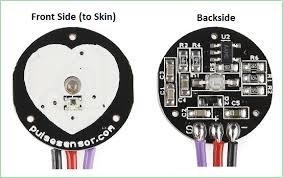
I have used pic18f46k22 microcontroller in this project. PIC18F46k22 microcontroller is one of the best production of microchip family of microcontroller. It has a lot of built in resources like more than 20 built in analog to digital converters and many other features. After PIC16F877A microcontroller, it is one of my favorite microcontroller from microchip medium level microcontrollers series. So now lets start with introduction of SEN-11574 heart beat pulse sensor. It has many applications and few of them are given below:
- exercise machines for heart beat measurement using workout
- heart beat meter for local use at home and many other applications
Recommended Components
The following components are used in this project or are helpful for building it with a PIC microcontroller.
| Component | How it’s used in this project | Buy on Amazon |
|---|---|---|
| PIC16F877A microcontroller | The 8-bit PIC MCU that runs the firmware and reads the sensor data in this project. | Check Price |
| PICkit 5 programmer/debugger | Programs and debugs the PIC by flashing the compiled HEX file to the chip. | Check Price |
| Pulse heart-rate sensor | The optical pulse sensor that produces the heartbeat signal read by the microcontroller. | Check Price |
| Breadboard | Solderless board for building and prototyping the circuit without soldering. | Check Price |
| Jumper Wires | Male-to-male jumper leads for wiring the components on the breadboard. | Check Price |
As an Amazon Associate we earn from qualifying purchases. Prices and availability are accurate as of the date/time indicated and are subject to change.
SEN-11574 pulse sensor introduction
SEN-11574 is very easy to use heart beat sensor for engineers and students. It consists of optical heart beat sensor circuit and amplification circuit and noise cancellation circuit and its internal circuit diagram is given in its data sheet ans shown below.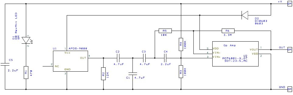 It has three pins and description of each pin is given below:
- +3 to +5 volt pin : you will supply +3 to +5 volt to this pin
- Ground: You will connect this pin with ground pin of power supply
- Signal pin: This pin is basically a output pin which gives output according to heart beat rate.
Components required heart beat pulse sensor interfacing with pic microcontroller
Followings components are used in this project:- PIC18F46K22 microcontroller : It is used to measure output signal of heart beat pulse sensor and send the value to 16 x 2 lcd for display.
- 16X2 LCD: Heart beat measured value is displayed on LCD.
- 8MHZ crystal
- potentiometer
Circuit diagram of heart beat pulse sensor interfacing with pic microcontroller
Circuit diagram of heart beat pulse sensor is given below and which is self explanatory.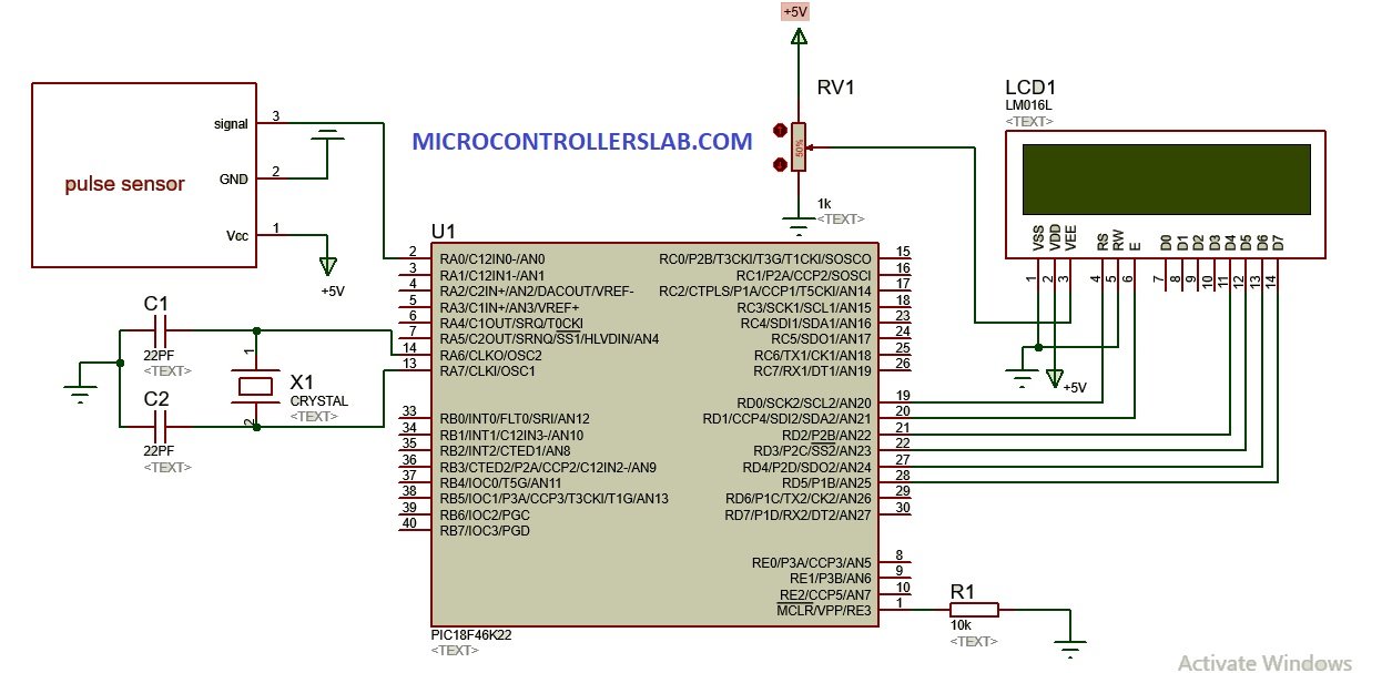
Code
sbit LCD_RS at RD0_bit;
sbit LCD_EN at RD6_bit;
sbit LCD_D4 at RD5_bit;
sbit LCD_D5 at RD4_bit;
sbit LCD_D6 at RD3_bit;
sbit LCD_D7 at RD2_bit;

sbit LCD_RS_Direction at TRISD0_bit;
sbit LCD_EN_Direction at TRISD6_bit;
sbit LCD_D4_Direction at TRISD5_bit;
sbit LCD_D5_Direction at TRISD4_bit;
sbit LCD_D6_Direction at TRISD3_bit;
sbit LCD_D7_Direction at TRISD2_bit;

enum {FALSE = 0, TRUE = 1};
char intro_msg[] = "ELECTRONIC HEART RATE MONITOR";
char temp_str[8], disp_result;

int rate[10]; // array to hold last ten IBI values
unsigned long sampleCounter = 0; // used to determine pulse timing
unsigned long lastBeatTime = 0; // used to find IBI
int Peak =512; // used to find peak in pulse wave, seeded
int Trough = 512; // used to find trough in pulse wave, seeded
int thresh = 512; // used to find instant moment of heart beat, seeded
int amp = 100; // used to hold amplitude of pulse waveform, seeded
bit firstBeat; // used to seed rate array so we startup with reasonable BPM
bit secondBeat; // used to seed rate array so we startup with reasonable BPM
int pulsePin = 0; // Pulse Sensor purple wire connected to analog pin 0
int blinkPin = 13; // pin to blink led at each beat

int runningTotal = 0; // clear the runningTotal variable
// these variables are volatile because they are used during the interrupt service routine!
unsigned int BPM; // used to hold the pulse rate
unsigned int Signal; // holds the incoming raw data
unsigned int IBI = 600; // holds the time between beats, must be seeded!
bit Pulse ; // true when pulse wave is high, false when it's low
bit QS;
int N_cnt, P_cnt;
int i = 0;
void InitTimer0(){ //timer0 is set to Interrupt every 2ms. PIC18F452 is running at 32MHz
T0CON = 0xC5;
TMR0L = 0x06;
GIE_bit = 1;
TMR0IE_bit = 1;
}

void Interrupt(){
GIE_bit = 0;
if (TMR0IF_bit){ //every 2ms

//READ HEART RATE FROM LCD
Signal = ADC_Get_Sample(0);
sampleCounter += 2;
N_cnt = sampleCounter - lastBeatTime;
if(Signal < thresh && N_cnt > (IBI/5)*3){
if (Signal < Trough){
Trough = Signal;
}
}
if(Signal > thresh && Signal > P_cnt){
P_cnt = Signal;
}

// NOW IT'S TIME TO LOOK FOR THE HEART BEAT
// signal surges up in value every time there is a pulse
if (N_cnt > 250){ // avoid high frequency noise
if ( (Signal > thresh) && (Pulse == FALSE) && (N_cnt > (IBI/5)*3) ){
Pulse = TRUE; // set the Pulse flag when we think there is a pulse
IBI = sampleCounter - lastBeatTime; // measure time between beats in mS
lastBeatTime = sampleCounter; // keep track of time for next pulse

if(secondBeat){ // if this is the second beat, if secondBeat == TRUE
secondBeat = FALSE; // clear secondBeat flag
for(i=0; i<=9; i++){ // seed the running total to get a realisitic BPM at startup
rate[i] = IBI;
}
}

if(firstBeat){ // if it's the first time we found a beat, if firstBeat == TRUE
firstBeat = FALSE; // clear firstBeat flag
secondBeat = TRUE; // set the second beat flag

return; // IBI value is unreliable so discard it
}


// keep a running total of the last 10 IBI values
runningTotal = 0; // clear the runningTotal variable

for(i=0; i<=8; i++){ // shift data in the rate array
rate[i] = rate[i+1]; // and drop the oldest IBI value
runningTotal += rate[i]; // add up the 9 oldest IBI values
}

rate[9] = IBI; // add the latest IBI to the rate array
runningTotal += rate[9]; // add the latest IBI to runningTotal
runningTotal /= 10; // average the last 10 IBI values
BPM = 60000/runningTotal; // how many beats can fit into a minute? that's BPM!
QS = TRUE; // set Quantified Self flag
// QS FLAG IS NOT CLEARED INSIDE THIS ISR
}
}

if (Signal < thresh && Pulse == TRUE){ // when the values are going down, the beat is over

Pulse = FALSE; // reset the Pulse flag so we can do it again
amp = P_cnt - Trough; // get amplitude of the pulse wave
thresh = amp/2 + Trough; // set thresh at 50% of the amplitude
P_cnt = thresh; // reset these for next time
Trough = thresh;
}

if (N_cnt > 2500){ // if 2.5 seconds go by without a beat
thresh = 512; // set thresh default
P_cnt = 512; // set P default
Trough = 512; // set T default
lastBeatTime = sampleCounter; // bring the lastBeatTime up to date
firstBeat = TRUE; // set these to avoid noise
secondBeat = FALSE; // when we get the heartbeat back
}
TMR0IF_bit = 0;
TMR0L = 0x06;
GIE_bit =1;
}// end isr
GIE_bit =1; // enable interrupts when youre done!
}
void main() {
int g;
OSCCON.IRCF0=0;
OSCCON.IRCF1=1;
OSCCON.IRCF2=1;
ANSELA=0x01;
ANSELB=0x00;
ANSELC=0x00;
ANSELD=0x00;
ANSELE=0x00;

Pulse = FALSE;
QS = FALSE;
firstBeat = TRUE;
secondBeat = FALSE;
Lcd_Init(); //initialize LCD
Lcd_Cmd(_LCD_CLEAR); // Clear display
Delay_ms(200);
Lcd_Cmd(_LCD_CURSOR_OFF);
Delay_ms(200);
Lcd_Out(1,1, intro_msg);
Delay_ms(1500); // First row
for(g=0; g<sizeof(intro_msg)-16; g++) { // Move text to the right 4 times
Lcd_Cmd(_LCD_SHIFT_LEFT);
Delay_ms(250);
}

Lcd_Cmd(_LCD_CLEAR); // Clear display
Delay_ms(200);
ADC_Init();
InitTimer0();


while(1){
if (QS == TRUE){ //New Pulse detected
Lcd_Out(1,1,"HEART RATE (BPM)");
Lcd_Out(2,1," ");
IntToStr(BPM, temp_str);
Lcd_Out(2,8,temp_str);
Delay_ms(2000);
}


}
}
I want to buy the code for this project. Is the code in MPLAB XC8?
Code is with Mikro c for pic
Can i do this project with the same code using PIC16F877A?
Yes you can do this
Can I do a project with same code using atmega16
hi bro same question did u get the answer and let me know if u got the answer
thank you
Hi
This code will work with PIC18F46K22 microcontroller only. but you can modify it to use with ATMEGA32 Microcontroller. you will need to change register for the peripherals that are used in this tutorial. But overall concept will remain same.
Hi, Do you have any idea if i how i can change to cod to work on pic16f1829?
Any help is welcome
Thanks
Pontus
Hi
yes you can change it. You just need to use proper configuration and control registers for peripherals used in this example.
Hi, you can update this video.
What the frequency you use for crystal oscillator?
150mHz
The crystal frequency is 8MHz!
Aoa ! Please tell me can i give it a go with this code using PIC 16f887 ? and which compiler did you use ? If mikroC, then please help me out because it is givin too much errors when i compile it using mikroC..
Hi, I tried this project and its showing the error: “AVR Program property is not defined” in Proteus. I am sure that the hex file has been loaded into the microcontroller. Can you help me?
We have not tried it with proteus. It seems to be the issue with your heartbeat sensor proteus library.
Did your code compile easily?
If so can you share the hex file please
did you make it in proteous if yes can you provide code and ckt diagram
Hi
can the above project be linked to GPS Module and GSM module
yes you can.
Hi
Can i use another sensor like SEN-0203
I could not find the SEN 11574
thanks
Can you help me with the code for PIC16F877A of same project.
can i use this code for pic18f452
can you give me the code and circuit diagram of a health monitoring system which counts heart rate using 8051 microcontroller
can i do this project on 8051 microcontroller