In this tutorial, we will learn how to perform USB communication between a Pic Microcontroller and a computer by using the computer as a USB host and the Pic Microcontroller as a USB device. Firstly, we will see how to interface a USB with a Pic microcontroller. In 2nd section of this article, we will see an example code to transmit data through USB. PIC18F2550 and PIC18F4550 from microchip have built-in USB device support. That means we can use them to create a USB device.
USB Introduction
USB, which stands for Universal Serial Bus, is a widely used connection interface that allows computers to connect with various devices such as digital cameras, printers, scanners, and external hard drives. It provides a standardized and convenient way to transfer data and power between the computer and these devices.
USB offers different transfer speeds depending on the version. USB 1.0 supports data transfer rates of 5 Mbps (low speed) and 12 Mbps (high speed). USB 2.0, also known as high-speed USB, supports a transfer rate of up to 480 Mbps. USB 3.0, also referred to as super-speed USB, boasts transfer rates of up to 5.0 Gbps. There is also USB 3.1, also known as super speed+, which supports transfer rates up to 10 Gbps.

USB Device
A USB device refers to any peripheral device that is connected to a USB host, such as a computer. These devices rely on the USB host for communication and power. USB devices can include various hardware components like printers, scanners, digital cameras, external hard drives, and more. They typically send or receive data to or from the USB host and may require specific device drivers installed on the host in order to function properly.
USB Host
A USB host, on the other hand, is a device that connects to and interacts with USB devices. It is responsible for managing the communication and power supply to USB devices. Common examples of USB hosts are computers, smartphones, tablets, and game consoles. USB hosts have specialized software and hardware that allow them to recognize, configure, and control the connected USB devices. They provide the necessary power and data transfer capabilities to enable the functioning of USB devices.
USB Pinout
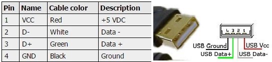
The USB pinout typically consists of four pins: Vcc (+5V), Data+, Data-, and Ground (GND). Here is a brief explanation of each pin:
- Vcc (+5V): This pin provides the power supply (+5V) for the connected USB device.
- Data+: This pin carries the positive data signal for USB communication.
- Data-: This pin carries the negative data signal for USB communication.
- Ground (GND): This pin is used as the reference ground for the USB connection.
Please note that the pinout may vary depending on the specific USB standard (such as USB 2.0 or USB 3.0) and the type of USB connector (such as USB Type-A, USB Type-B, or USB Type-C).
USB Programming Pic Microcontroller
In this section, we will see how to configure the Pic Microcontroller USB module to use it as a USB device. We will use MikroC for Pic compiler in this tutorial, If you do not know how to use MikroC for Pic, you can refer to these tutorials:
- How to Use “MikroC PRO for PIC” to Program PIC Microcontrollers
- Pic microcontroller programming in c using Mikroc Pro for PIC
The main steps involved are:
- Step#1 Clock Generation
- Step#2 Circuit Constructions
- Step#3 Programming the Microcontroller
- Step#4 Burning the code in Microcontroller
- Step#5 Device Drivers
- Step#6 Circuit Working
Clock Generation
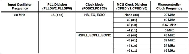
P18F2550/4550 supports low speed (1.5 Mb/s) and Full Speed (12 Mb/s), so for USB, we have to select a specific clock. An internal clock of either 6 MHz or 48 MHz is required because of timing requirements imposed by USB. However, there is a problem in using the crystal of 48 MHz. This crystal is of high cost and it also creates noise. Since the higher the crystal frequency, the greater the noise. There are numerous choices to achieve the USB module clock requirement which still provides flexibility for clocking the rest of the device from the primary oscillator source. Here, the crystal oscillator used with PIC18F4550 for USB interfacing is a 20 MHz crystal oscillator. It is used for the internal oscillation of the microcontroller and is connected to pins 13 and 14 of the MCU.
Configuration Bits Setting
Open the project settings page in MikroC for Pic compiler and perform the following settings according to your desired crystal frequency.
In the case of 20MHz crystal:
- Set the “Oscillator Selection” to HSPLL. It will give 20 MHz at the input of the “primary oscillator”
- Set the “PLL prescaler selection” to divide by 5, so we get 4 MHz which are multiplied by 24 to get the 96 MHz for the USB
- Set the “USB clock selection” to 96 MHz divided by 2
- Set the “System clock postscaler selection” to 96 divided by two.
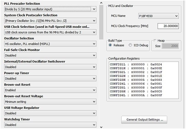
Finally, the Oscillator frequency is set to 48 MHz. (96 MHz/2=48MHz)
USB Interfacing Circuit with PIC Microcontroller
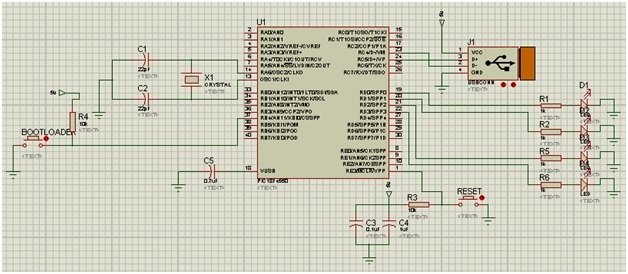
The circuit diagram shown in the image depicts the USB interfacing between a PIC microcontroller (specifically the PIC18F4550) and a computer. Let’s break down the components and connections in the circuit:
- PIC18F4550 Microcontroller: This is the main component of the circuit and serves as the USB device. It communicates with the computer through the USB connection.
- Crystal Oscillator: A 20 MHz crystal oscillator is connected to pins 13 and 14 of the microcontroller. This oscillator provides the required clock signal for the USB module.
- Voltage Regulation: The input voltage to the microcontroller should not exceed 5V. Proper voltage regulation must be implemented to ensure the microcontroller operates within its specified voltage range.
- LED Indicators: Two LEDs, connected to pins RD0 and RD1 of the microcontroller, are used for communication purposes. They provide visual feedback to indicate the status of the USB communication.
- Control Pins: The circuit includes two control pins, RD2 and RD3, which can be used to control other external components such as motors, relays, or servos. In this circuit, they are used as control pins alongside the LEDs.
- Reset Button: A reset button connected to pin 1 of the microcontroller allows for resetting the microcontroller if needed.
- Bootloading Button: Another button connected to pin 37 of the microcontroller is used for bootloading operations.
- Connections: Various connections are made between the microcontroller and its associated components, such as power and ground connections, to ensure proper functioning of the circuit.
It’s important to note that the circuit diagram represents the physical connections between components and does not include the detailed programming logic or firmware implementation required for USB communication. The circuit needs the appropriate device drivers installed on the computer to establish proper communication.
MikroC Code
The code for USB interfacing with a microcontroller is given below. However, to use this code, you have to add the device driver as well. Before using this code, the user should create a USB device driver by going to the tools of Mikro C for PIC and clicking on the HID terminal. Generate the descriptor.c file and paste it into your main code folder.
The MikroC Pro for PIC software offers an effortless solution with its integrated USB HID library. With this library, the communication between a host device and a slave device connected via a USB bus becomes an easy and seamless process.
// Define buffers in USB RAM for data transfer
unsigned char readbuff[64] absolute 0x500;   // Read buffer
unsigned char writebuff[64] absolute 0x540;  // Write buffer

char cnt; // Counter variable
char kk;  // Temporary variable

// Interrupt service routine for USB communication
void interrupt() {
   USB_Interrupt_Proc(); // Handle USB servicing inside the interrupt
}

void main(void) {
    // Configure all ports with analog function as digital
    ADCON1 |= 0x0F;

    // Disable comparators
    CMCON |= 7;

    // Enable HID communication with the specified read and write buffers
    HID_Enable(&readbuff, &writebuff);

    while (1) {
        // Wait for data to be received
        while (!HID_Read())
            ;

        // Copy received data from read buffer to write buffer
        for (cnt = 0; cnt < 64; cnt++)
            writebuff[cnt] = readbuff[cnt];

        // Send the data back in the write buffer
        while (!HID_Write(&writebuff, 64));
    }
}
The code for the microcontroller is written with special software that has its own programming language, similar to C, such as MPLAB or MicroC software. The code is then compiled to generate the respective output. In this process, a “.hex” file is generated, which needs to be burned or fused into the microcontroller.
Demonstration
Connect the USB cable from the computer to the USB interface. Even after completing the circuit and programming the microcontroller, it will not start working properly. As we know, new hardware installation requires drivers for Windows to be detected by the system.
For Driver Installation and Bootloading operations, we need to download and install the USB MICROCHIP FRAMEWORK from the Microchip website.
To start the circuit, we have to initialize it in BOOTLOAD Mode. In the USB interface circuit, as already explained, there are two buttons: one is the RESET button and the other is the BOOTLOAD button.
- HOLD the RESET button.
- Keep the RESET button pressed and then hit the BOOTLOAD button once.
- Then release both buttons.
- The window will then detect the PIC18F4550 USB hardware and ask for drivers for this PIC18F4550 circuit/board.
- If the window does not ask for drivers, there may be some problems with the circuit.
- Suppose the drivers for this USB device are located in C:\MCUSB\MCUSB Driver\Debug.
Conclusion
In conclusion, USB communication between a PIC microcontroller and a computer is a valuable skill to learn for anyone working with embedded systems or microcontroller projects. This tutorial provided an overview of USB technology, its components, and the steps involved in configuring a PIC microcontroller as a USB device. It also explained the necessary circuitry and programming code needed to establish USB communication. By following the instructions and guidelines outlined in this tutorial, developers can enhance their projects by enabling seamless data transfer and interaction between the microcontroller and the computer. USB communication opens up a world of possibilities for creating innovative applications and expanding the capabilities of microcontroller-based systems.
Related content:
Hi there. Do you have a higher resolution of the schematic please? Its very hard to read in the present form. Thanks for the article!
can we use pic microcontroller as usb hid terminal, i mean microcontroller to usb hid communication